Black Frog Posted September 19, 2014 Author Share Posted September 19, 2014 The heads of my linkage pins all have a flat on the side.That flat goes up against the tab on the toggle arms, and the flat also goes up against the ram. Prevents the pin from rotating in place during use.My pitman had an old style grease fitting on the top, I'm wondering about switching that over to an oil cup instead.EDIT... the more I see pictures of rebuilt ones, seems like they all have the grease fitting on the pitman. Good enough for me. Quote Link to comment Share on other sites More sharing options...
Don Hanson Posted September 20, 2014 Share Posted September 20, 2014 I like the no paint look. Goin to be a great lookin hammer! Quote Link to comment Share on other sites More sharing options...
Black Frog Posted October 1, 2014 Author Share Posted October 1, 2014 More progress mixed in with being way too busy with everything else.Instead of trying to go up in size to correct the oblong holes in the linkage arms and hope for a decent result, I decided to weld them all shut and start over fresh. Then I can control exactly where the hole placement will be and ream them to size. I tweaked a few of the ears on the hydraulic press so that they are parallel with each other. Ground the welded holes flush, pressed in new bronze bushings, and now about ready for machining. Quote Link to comment Share on other sites More sharing options...
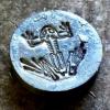
Black Frog Posted October 1, 2014 Author Share Posted October 1, 2014 Once I pressed out the pitman bushing, I could see how poorly it had been done at the factory.Only about half of the bronze bushing was making contact with the bored cylinder in the pitman head.One side's diameter of the hole was about .012" larger than the other other side, and very poorly cut.....So I corrected that as best I could, just taking as little as possible off the diameter to make it a true cylinder again.I'll have to machine a new bronze pitman bushing, hopefully next week sometime.This is after the correction, you can see on the original bushing where only part of it was making contact. Quote Link to comment Share on other sites More sharing options...
Daniel S Posted October 2, 2014 Share Posted October 2, 2014 That hammer is going to look great when you're finished. Quote Link to comment Share on other sites More sharing options...
divermike Posted October 5, 2014 Share Posted October 5, 2014 When I hosted the Gennessee chapter of the New York Blacksmiths I painted all of my tools colonial red so there would be no confusion of tools. So when I found a little Giant the same color, I figured it would fit in with all my stuff just fine, and it does! Quote Link to comment Share on other sites More sharing options...
Black Frog Posted October 17, 2014 Author Share Posted October 17, 2014 More progess. This is taking a lot longer than I had planned for, but turning out better than I had hoped.All the linkage arms and ram have the new holes located, drilled, and reamed to size.Fixturing all the linkage pieces on the mill for correct planes and parallelism was challenging, but I think it turned out great.Six new linkage pins cut for a beautiful fit, they slide into the reamed holes with a nice 'thunk' into place.The pins are sized for about .002-.003" under. Just right for a nice oil film to wick in.I'm starting to see the daylight at the end of the tunnel. :) Quote Link to comment Share on other sites More sharing options...
VaughnT Posted October 18, 2014 Share Posted October 18, 2014 You do incredible work, Frog. I can't wait to see how she looks when all's finished. Quote Link to comment Share on other sites More sharing options...
LastRonin Posted October 19, 2014 Share Posted October 19, 2014 Video... that's what I'm waiting for... video of her first hot meal after her recovery. :) Quote Link to comment Share on other sites More sharing options...
Black Frog Posted October 21, 2014 Author Share Posted October 21, 2014 I'll post a vid when she's on the maiden voyage after rebuild.Still lots to do before that happens.But today's little step forward was boring the new pitman bushing to proper size and installing the new zerk fitting. Quote Link to comment Share on other sites More sharing options...
LastRonin Posted October 22, 2014 Share Posted October 22, 2014 (edited) I love the contrast in that latest photo, between the steel and bronze. I guess I will have to be satisfied with the still photos until she's back up and running. Just keep them coming. She's looking great, and I bet she'll work a treat when you're done. Added: Just look at that picture. It's art. Edited October 22, 2014 by LastRonin Quote Link to comment Share on other sites More sharing options...
Black Frog Posted October 22, 2014 Author Share Posted October 22, 2014 LR, the bad news is that there's a retaining washer plate that keeps the pitman on the flywheel crankpin.None of the bronze bushings will be visible when it is all together.The good news is that I decided to redo the washer plate for a bit more visual appeal. Coming from the factory that plate was rather rough cut, it didn't need to be anything better than that to do its job. I was going to recut a new washer, then I thought that original one has lasted all this time, it deserves to be on there for another lifetime.I took the original washer plate and gave it a skim cut to smooth out the outer surface and get rid of the original machining chatter marks.Then added a decorative groove and polished it up for some shiny factor. I like it. :)Today was the first day that all linkage arms and pins were assembled for a test fit.I'm quite happy with how it all went together. My new main spring has arrived as well.Now I can move on to working on the frame. Quote Link to comment Share on other sites More sharing options...
Black Frog Posted October 27, 2014 Author Share Posted October 27, 2014 Probably the last warm weekend we were going to have here, so I put in a lot of time the last few days making good progress.Got the base plate painted and fit, rubber matting cut and fit.Base is 6x6's with 1/2" steel plate on top.Got the frame and all parts clear coated! This is the first time the frame met the base.And then the first trial fit of all the linkage components on the hammer with new main spring.Going well so far, next I need to come up with a motor mount design along with the flywheel brake.But I think the hardest part is now behind me. Quote Link to comment Share on other sites More sharing options...
oakwoodironworks Posted October 29, 2014 Share Posted October 29, 2014 Really like that base! Quote Link to comment Share on other sites More sharing options...
kubiack Posted October 29, 2014 Share Posted October 29, 2014 It is looking good. I'm enjoying watching your progress so keep posting. Quote Link to comment Share on other sites More sharing options...
Black Frog Posted October 29, 2014 Author Share Posted October 29, 2014 I entirely underestimated how long all this was going to take me, but I do what I can when time allows.Next up for me was figuring out a brake system for the hammer. I've seen several designs of LG brakes.One critical component for me was that I do not want to drill any holes in my frame. Making a brake would be much easier with mounting holes in the frame, but I wanted to avoid that. At QS this year I bought a LG leather brake strap from Mr. Phil Cox who works on a lot of LG's. I liked that general idea the best, then I just had to come up with a mounting and operational linkage.With as tight tolerance of all the treadle and clutch fork pivots and linkages I have, I figured I could use that for my vertical motion of the strap brake. I also could have ran another vertical rod from the treadle, but in the end didn't like the idea. If this doesn't work out how I think it will, I can always go that route.The green lever gets mounted to the clutch fork pivot pin. When the treadle is depressed to engage the clutch fork, it rotates that pin counterclockwise a bit. So when that treadle is depressed, it will also rotate my green down lever arm a bit (ccw). I add a L-arm mount to the ram guide bolts that contains a boss for another pivot pin. By playing with linkage lengths and distances away from pivot centers, it isn't too hard to develop what I figure I need as roughly 1.5" of vertical movement directly belown the flywheel from the being depressed.And here is the L-arm brake pivot mount for the ram guide. I added a bronze bushing and oil hole as well.I added a few tack welds to make sure the boss fit in the plate stays there for life.The boss for the pivot pin is 1.75" long, and goes through the plate just like the model. That should provide nice stability for the linkage up front. With rather tight tolerance linkage pins and arms without much play at all, there shouldn't be too much slop to deal with. Quote Link to comment Share on other sites More sharing options...
kubiack Posted October 29, 2014 Share Posted October 29, 2014 I have some picture of a break setup that Sid built for a Transitional 25 pound hammer. It uses the same arrangement of a pivot mounted to the ram guide. The connection to the treadle seems a lot simpler than being run through the fork pivot pin. As best I can tell it does not use any extra holes in the frame either. Let me know if you want me to post some picks of it. One thing that I don't like about the way you have it drawn up is you are going to a bit of lag as the play in all the clevis is taken up when you let of the treadle. There is a clevis on each end of the treadle rod, any sideways movement in the pivot pin, and another set of clevis between the pivot pin and the ram guide. I think a more direct connection to the treadle itself would be better. Quote Link to comment Share on other sites More sharing options...
Black Frog Posted October 29, 2014 Author Share Posted October 29, 2014 My home made pins only have a few thou of play, quite close fit. What I didn't mention is there's a down spring that pulls the brake strap arm downward attached to the bottom ram guide bolt. This pulls any slop or play out. The treadle is always pulling against that spring through the linkage. If there's slop it is only evident when you start to depress the treadle. I have some pics of Sid's brake setup. What I'm doing here is very similar to Phil Cox's arrangement. Seems to work great from what I've seen. Quote Link to comment Share on other sites More sharing options...
Black Frog Posted October 31, 2014 Author Share Posted October 31, 2014 After more modeling, thinking, looking at other's pictures, I'm putting the brake fabrication on hold and moving onto the motor mount.I can have an operating hammer without a brake, I cannot have an operating hammer with a brake and no motor mount.... It also gives me more time to contemplate the brake design while having a functioning hammer in front of me.Latest project, prompted by some pictures Kubiack was nice enough to share, is some upper bearing oil cup caps. The main shaft on my hammer does have a bit of scarring in one spot where something must've got done through the oil cup and wedged itself against the spinning shaft at some point in its life. Earlier I had thought of cutting some 1/2" felt to the interior size of the oil cup. That would allow the oil to seep through and keep and particles from getting down to the shaft. But I saw a picture of some simple sheet metal caps, and thought that would be a quick project that would be worthwhile.I had some plastic laying around and machined these oil caps to size. I still thinking of putting the felt in the cups. It might slow down the oil delivery and meter it out a bit slower over time, which might be a good thing. Quote Link to comment Share on other sites More sharing options...
VaughnT Posted October 31, 2014 Share Posted October 31, 2014 Is there nothing you can't do, Frog? The use of newspaper in the oil cups is ages old. It does just like you were thinking, metering the oil flow and filtering out any solids that might get in. Like anything else, you have to jam it in tight, getting it into the orifice. Otherwise the oil will just flow around it. Quote Link to comment Share on other sites More sharing options...
Jim Coke Posted November 1, 2014 Share Posted November 1, 2014 Greetings Frogman. What no auto oiler system ? Lol. Forge on and make beautiful things. Jim Quote Link to comment Share on other sites More sharing options...
Black Frog Posted November 1, 2014 Author Share Posted November 1, 2014 Cool, I have some thicker oil felt for use in lathes that will work great in there. :-) Quote Link to comment Share on other sites More sharing options...
Black Frog Posted November 6, 2014 Author Share Posted November 6, 2014 I tried the felt in the oil cups. I used a cork borer to make some nice slightly oversized circle cutouts of felt that I pushed down into the oil cup holes. Either the felt I tried is too dense, or I packed it in too tightly. I put some bar oil in the cup, and 24hrs later none had seeped down through.... I was using bar oil for the experiment, and it was about 40 degrees out. So now I'll try a circle cutout that just slides into the hole without much force and do it again. But more progress on the motor mount. I did not want to drill holes in the frame of the hammer. I also have seen several LG's that get tippy in use with a beefy motor hanging off to one side of the frame, so I thought I could avoid mounting the motor directly on the hammer. Since I have the 1/2" steel plate on the base, it gave me a nice footprint of steel to mount things to.I know most people are using V-belts to drive their hammer, but I sure liked the idea of using flatbelts, more like the original useage. I noticed Aaron Cergol's 50# LG running with a 1" flat timing belt and timing pulley on the motor, that seemed like a great idea to me. I started with the intention of using a flat timing belt to drive my hammer.I decided to make a hinged motor mount that comes off the base plate, and put the motor quite low on the mount to keep the center of gravity low. Going to use a V-belt from the motor to the reduction shaft (held by a set of pillow block bearings), and from the reduction shaft to the hammer clutch pulley using a flat timing belt. By doing some pulley and RPM calculations coming off my 1725rpm motor, I wanted to reduce the rpm to about 900-1000rpm at the reduction shaft. I caclulated the diameter of the timing belt pulley to get the final hammer rpm. And easy v-belt pulley change in diameter will make it fairly painless to dial in a desired rpm range of the hammer in use.The square tube frame turned out nice, motor will be mounted in the mid-section with the extra vetical support tube. This will give me a large vertical span of motor mounting options and V belt sizes to the top shaft.Picture below is about the position the mount will be in during use. The motor pulley will be out the backside with the v-belt running up to the top pulley. There will be hinge pins on the bottom of this mount so the whole ladder assembly can tilt toward or away from the hammer, and I'll install a push bolt that runs from the ladder to the frame that will adust the timing belt tension for the clutch pulley. The ladder mount will be about vertical when in use with a standard 48" H-series flat timing belt. I may have to tinker with hammer RPM once I try it for real, but going for around 300-320rpm top speed. Adjustments should be fairly easy with lots of common v-belt pulley sizes available. Quote Link to comment Share on other sites More sharing options...
Black Frog Posted April 20, 2015 Author Share Posted April 20, 2015 (edited) I had a few people ask me how my 25LG turned out, and the other thread reminded me that I never added a photo of the working hammer on this thread.This thing works fantastic, I don't think it could have turned out better. I love using the timing pulley and timing belt as the drive. Lots more surface area of contact on the clutch pulley, all that is needed on my push bolt is very light tension to make the hammer work nicely. More like using original line belts vs. using v-belts as the drive. I like having the weight of the motor down low, and with the beefy base this thing is solid. I made a fancy reverse twist treadle rod for the hammer just to dress it up a little more, the picture of the twists and shadows makes it look a little wonky and out of kilter, but it is nice and straight.I also made a tool saddle for the lower die that accepts 1" square shaft. I've been slowly making different spring tooling and lower die tools for it. Still haven't got around to adding the brake system to the hammer, now that I'm working through a 50# Mayer I might add the brake to that first instead.... Edited April 20, 2015 by Black Frog Quote Link to comment Share on other sites More sharing options...
Recommended Posts
Join the conversation
You can post now and register later. If you have an account, sign in now to post with your account.