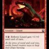
July 4, 200916 yr Hi. I am having trouble getting my ejector style burner working. I read in this forum that ejector burners induce air more efficiently than linear burners. I made an ejector burner similar to ones seen posted here, and it seems to have problems drawing enough air. The flame is primarily colorless and has some yellow tips. The main part is that the burner does not seem to make that sucking sound that I am familiar with. To do a comparison, I ran it along side a known working linear burner. This is one made from the plans from the anvilfire site. It is very similar to BP0192, and uses a .023 Tweco style MIG tip. The working linear burner produces a sharp conical blue flame. The ejector burner is based on 3/4" plumbing pipe. It has 3 air slots, each one about 1/2" wide and 3" long. They were made long so the burner could be choked with a collar. It turned out that any choking of the slots made the flame drift lazily upward, with a lot of yellow tips. Obviously, it was running rich. The burner was made with 3/4" pipe, with the back end made out of 1/2" pipe. 3 pieces of sheet metal were welded between the pipes to make the slots. Ahead of the slots is a slide fit 1/2" pipe flared at the inlet and fullered in the middle. This was intended to act as a venturi. The insert was filed with a round file so that it smoothly transitioned into the main burner pipe wall. The nature of the flame was almost unaffected by slight changes in alignment of the jet or the position of the jet up or down in relation to the slots. It was the clearest if the venturi was slid out into the slot area with the jet poking into the narrow section. The main problem that I observed is the lack of suction. I would expect a small sheet of paper to be drawn to the air slots when the burner was in operation. The things that affected burner operation was the amount of choking. More choking caused an upward sloped yellow flame. Also, MIG tip nominal size affected the results. Less yellow was produced by a 0.023 tip as opposed to a 0.035 one. Position of the jet did not seem to make much difference. The burner was operated from 5 psi to 20 psi. 5 psi was useless (too rich), and 20 psi used too much gas. The acetylene regulator could not deliver this flow rate. I am enclosing a picture of the burner. I made one ejector burner earlier, and it was a similar failure. Too rich, and not enough suction. That design was based on Lionel Olver's "upwind burner" from backyardmetalcasting.com. I wrote the failure off to inexperience. But now, with such a good performing linear burner, it is hard to see what is so touchy about the ejector style. :confused: The linear burner is dead simple. Plumbing pipe screwed into a bell reducer, with a 1/8" pipe nipple welded on a post with a Tweco MIG tip screwed into it. It works well at high and low pressures, and produces an efficient and perfect looking flame. Is it obvious what is wrong with this current burner? Thanks.
July 4, 200916 yr I don't know quite where to start. The Oliver upwind is one of the older designs out there but not significantly different than other ejectors. As always the specific style is less important that getting the finicky details right. The one thing that really jumps out at me is what appears to be a bushing reducer in the intake end of the burner tube. If that's what it is, that's your kiss of death for getting that one working at all. My 1" ejectors run on 0.045 mig tips and are proven steel melters if you turn the psi up a bit much. Like when a student is busy yakking instead of watching his work in the fire. Darned if I know how the psi got bumped up and AFTER he spent so much time and work on the piece. Darned shame it was, a DARNED shame . Of course he pays a LOT closer attention now. Anyway, I haven't built a slotted intake burner like your's or Mike Porter's. At a glance though you've really over complicated it like the Oliver. Still the basics are the same regardless. Try this on your next one if you opt for another slotted intake configuration. Start with black pipe. Determine the tube diameter you need by calculating the volume of your forge and it's intended purpose. If all you want to do is general forging then high orange is probably enough heat so figure 1 ea. 3/4" burner to every 400 cu/in volume PROVIDED the volume is reasonably spherical or cubical. One long dimension will cause uneven heating. If you plan on welding with your forge occasionally then 1 ea 3/4" burner for every 350 cu/in with the shape caveats of course will do the trick. If you plan on doing a LOT of welding and want positive experiences on the HOT end then figure 1 ea. 3/4" burner for every 250-300 cu/in. 1" tube is almost 2x the cross sectional area of a 3/4" tube and puts out a bit over 2x the heat so calculate accordingly. If you want a long narrow forge say for heat treating swords then you're much better off with using more smaller burners for even heating. Heat treating needs heven heat so it's the one time I recommend mounting burners tantential to a cylindrical chamber. Okay, now you've determined what size and the number of burners it's time to get going on them. Here are the ratios you need to use to determine the important aspects of a burner. They all start with the throat diameter. The throat is the narrowest part of the burner tube where the air and gas enter. I'll use a 1" throat for example. A 1" throat means the tube length, (this is the distance from the throat to the burner outlet or nozzle) needs to be 8-9". A 1" throat means you need the air intakes to have a minimum 2x the area or approx 1.6 sq/in. More is okay as you can choke it down but less means you won't be getting sufficient air to a straight tube burner. I used to list the distance of the jet orifice from the throat but I've seen too many examples of well tuned screamingly HOT burners with jet depths ranging from an inch or more back to right in the throat. I have good luck in my burners by setting it about about .75 x the throat dia. So, here they are again. Tube L = 8-9 x throat dia. Intake area = 2x throat dia. Frosty Edited July 4, 200916 yr by Frosty
July 4, 200916 yr Okay, round 2. I had to feed the goats and sent the last message rather than take a chance of losing it while I was gone. Anyway. Here's how I'd build a 1" slotted intake burner. I'd want 8-9" after the throat and I've decided on three slots. Mike Porter likes odd numbers of slots for a more laminar intake air flow. So, three slots it is I'll make them 1/2" wide and between 1 3/4" and 2" long while leaving just the threads on the end of the long nipple. Okay, I can find either a 1" x 10" nipple or a 1" x 12" nipple one's a little long, the other's a little short. I buy the long one because they're easy to trim. Starting at the back end I screw on a 1" x 1/8" bell reducer, snug it and make match marks so I can return it to reasonably the same position if I have to remove it during construction. If I have a lathe (I do) I'd chuck the current assembly up and clean out the threads in the reducer so I can make an adjustable depth jet holder. Having a lathe I'd bore and thread a piece of 1/2" rd and tap the bell reducer to accept 1/2" coarse threads. I'd bore and tap it 1/4"x28 for the mig tip. Lacking a lathe I'd buy a 1/8" pipe tap and chase the threads in the bell reducer from the inside so I can use a 1/8" MPT to 1/4" compression fitting and still thread in a 1/8" pipe nipple from the other end for my valve and gas supply. I really like 1/8" MPT to 1/4" compression fittings for mounting my jets. You have to take the correct drill size for tapping 1/4"x28 with you to the plumbing supply and check the ID of the brass fitting to make sure you can tap it. There is variation is the ID of the fittings so you have to check, small can be chased out but too large and you can't get deep enough threads tapping it. The threaded section on mig tips is VERY short so you need to tap good clean threads in the fitting though you don't need to go very far with them. This is in it's own paragraph so the important aspect doesn't get lost in the details. Tap the 1/8" MPT to 1/4" compression fitting in the compression fitting end. The 1.8" MPT then threads into the inside of the modified bell reducer. Screw the mig tip into the fitting and the fitting into the bell. So, now you have your jet installed in the bell reducer. Measure how long it is from where the bell reducer stops on the burner tube (use the match mark) to the end of the mig tip. This will be the departure point for where the intake slots start. (Never having built one of these I don't have a hard number for where the slots should begin but this leaves plenty of slack for adjustment) Mark your intake slots evenly around the bore and using a drill press or if you're lucky mill or if you have a lathe the lathe with mods to mill. Either drill and saw out your slots or mill them out. In either case file them smooth, Mike Porter insists it's really important to efficiency in the final product so what the hey, file it up smooth. Now you have the intakes, all that's left is the tube length. Measure from the bottom of the intake slots, where the filed taper ends 8-9" and if there's a threaded end close you're good if not cut it off. Now this should get you in the ball park provided the single MOST important detail is observed. The jet must be as close to perfectly centered down the tube as you can get it. Hookig it up to a water supply and squirting water through the jet is the easiest way to see how she's aimed I know of. Small adjustments can be made by simply prying the mig tip a little with a narrow screw driver. Mount it in your forge however you like and start tuning it. In this configuration tuning is done by moving the jet's relationship to the air intake slots. If it isn't drawing enough air trim the jet so it's farther from the throat. Or ou may have to widen or lengthen the intake slots, maybe both. If it's drawing too much air you're golden, make a choke. Frosty
July 5, 200916 yr Author Hi Frosty. Thanks for the detailed reply. I still need to digest the second part of it. I am using a 3/4" burner for an approximately 300 cu in forge volume. I would like the forge to reach welding temperatures occasionally. My mini forge with the linear induction burner will reach welding temperatures, but just barely. The thing in the inlet of the burner tube is a homemade venturi. I made it out of a piece of black pipe with a spring fuller. Just like a flared candle holder. So, this does not work well with the ejector design? There are 3 slots in my burner, each 1/2" wide by 3" long. Maybe a little too much, but I can shut them off with a collar choke. And, as I mentioned previously, the choke did now work out well at all. It only made the problem worse. That's a clever way of using a bell reducer to capture the gas injector tube. I just used a 1/2" pipe with the 3 screws holding a 1/8" pipe. As everyone knows, the 1/8" pipe is too wide to tap for cut decent 1/4-28 threads in. But, the pipe can be tapered in a v swage. This is a good use for an ASO. Even a junk cast iron anvil can be used for tapering pipe on the step. So, maybe if I get rid of the venturi (I thought it would be helpful, looking at BP0192) things will work better. This needs a little more experimentation. Thanks for the suggestions and dimensions. Of course, I'm not averse to trying out a cross or tee (Frosty) burner design. The
July 5, 200916 yr I keep hearing how simple these atmospheric burners are and then I see posts like this. We made a forge in one hour at a conference during lunch break. Five gallon bucket, enough kaowool to go around the inside, stack of bricks at both ends. Poke a hole in the side, stick in a 1-1/2 inch pipe with a hole in for a copper tube, stuck a hair dryer in the pipe and lit it off. Welding out of it an hour later.
July 6, 200916 yr Yeah, your "venturi" isn't doing you any good at all. When people refer to these as "venturi" burners it's a misnomer, only commercially made inducers actually have a venturi in them, mine certainly don't. With 1/2" x 3" intakes it should be drawing way more air than necessary, that it doesn't and there are no other obstructions it means it's jet and throat. And that's a really short list of possible problems. The jet is misaligned or WAY too large, your's is neither or it's the throat. Your's has the "venturi" so that's the first thing to eliminate on the trouble shooting list. Gun burners are great, I only have a couple negatives on my list, you're tied to power and it's a real challenge to get something workable for a forge like my variable volume forge. With naturally aspirated burners I can just turn them on or off meaning I can literally change the configuration, size, shape, etc. of the forge without even turning it off let alone waiting for it to cool. Were I using a gun, cooling wouldn't be a problem because I'd have to adjust the blower and fuel to reflect the additional or subtracted burner. That's more complicated than it sounds because you're doubling, tripling or quadrupling the air and gas or dividing it by fractions which means gross adjustments, then tuning. It's not a big thing if you don't change the number of burners in your forge. AND I may be overstating the hassle seeing as I've never tried a multiple configurable nozzle gun burner in a forge. (Sorry for the clunky descriptive sentence) Personally I don't have a dog in the race one way or the other, guns and NA burners both do the job well, each have their plusses and minuses as does everything. I just have some expertice with the things. Frosty
July 7, 200916 yr Author Hi Grant. These "simple" atmospheric burners are not simple unless you exactly follow the instructions. And there don't seem to be any explicit instructions for the slotted tube variety online. There are several pictures of successful ones, but apparently, that isn't enough. The best instructions I have seen are those referred to by Reil's site and the simple atmospheric burner plans on Anvilfire. Frosty, I tried getting rid of that stupid venturi pipe, and the burner worked much better. I was able to achieve an oxidizing flame with the 0.023 MIG tip, and a barely neutral flame with the 0.035 MIG tip. The larger tip should be the appropriate size, and I think I know what the problem is. The flame leanness is not greatly affected by the position of the injector. It is slightly affected by the alignment, and more affected by the degree of choking with a collar around the air slots. It is affected a lot by that stupid venturi. So, rounding the burner tube inlet should be helpful to smooth the air transition. It might even be better to smooth the areas between the strips welded to the burner tube. This is getting a little time consuming and complicated. I have a blower and a fabricated air gate sitting on the shelf begging to be used. Also have the BBQ regulator (low pressure) and some 1.5" pipe. Just in case, there is also a hairdryer available, but this seems awfully crude. I should probably also source a needle valve. No big hurry. This forge does not have to be completed until November.
July 8, 200916 yr evfreek in the burner pic the mig tip is way to far from the tube, I believe your slots are too large and the mig tip must be centered to work correctly.
July 8, 200916 yr BBQ regulators are only designed for 60,000 BTU MAX. I wouldn't think that would be near enough, volume for a forge. My weed burner has a only a needle valve, no regulator, it goes from yellow flame to 500,000 BTUH, with a 1/16" orface, if you regulate down to 11.0 inches W.C. that would be only 27,286 BTU. Keith
July 8, 200916 yr If you do a blown burner consider very seriously Jymn Hoffmans burner designhttp://www.iforgeiron.com/forum/f7/coal-vs-gas-7197/
July 11, 200916 yr Author Hi Sweaney. Those suggestions sound like they are on target, based on a document I saw on the Internet written by Michael Porter for the Hammer's Blow. I will rebuild the burner with smaller slots and an injector tube closer to the burner tube mouth and see what happens. I did not see this document until I had trouble and started searching. Anyway, the burner is close to working. Just a little leaner. Boy, what a lot of fiddling, though. Still, it beats watching TV, but not by much. Doesn't beat hacksawing large blocks of tool steel or chopping charcoal. I guess it's a matter of dimension. I noticed another post recently complaining about rich operation because of no venturi. Oh well, I can send him mine :)
July 16, 200916 yr I like playing with burner designs This link can help a lot with design.Burner History 101 - Energy Notes - Process Heating there is a series of articles that cover most burners in use today. Good info. good read when you cain't sleep. :)
July 17, 200916 yr Mike Porter's Gen 5 (his latest and probably last type) has slotted intakes. He likes an odd number and bevels the downwind end to minimize turbulence. Mike and I differ in that respect, he strives for as laminar an air flow as possible and I prefer a little controlled turbulence to aid air fuel mixing. 0.035 mig tip is about right for a 3/4" burner. If you can get slightly oxidizing you're golden, because then you have something to choke when you need a rich fire. Most of the time a little lean is better for safety's sake, less CO generated. Like most things, it's the first couple that take forever to get right. Once you get your particular version dialed in subsequent units go pretty quickly. I probably spent close to a week of fiddling to get my first "T" to burn right. The next one took a couple hours and didn't have nearly as much stuff, the first one was made with almost everything adjustable. Anyway, by the 4-5th I was making them in about 20-30 mins plus tune time. now I can do it in about 15 mins plus tune time. Gun burners are good, they're easy to build and easier to tune, you're just tied to power and the blower can be expensive. Frosty Edited July 17, 200916 yr by Frosty
July 18, 200916 yr Author Hi Sweany and Frosty. After cutting and shortening the slots and moving the injector tube forwards, the burner works quite a bit better. Still not very lean, but no green flames. This is marginal, and may not work so well in a forge, but it would still be interesting to try. Sweany, thanks for the burner notes. I have done a lot of searching on the Internet, and have not found this. But, I have been searching for something a bit different. I have been wondering about where the maximum leanness ratios are coming from, i.e. 20:1 and 28:1 or 29:1. I searched these terms and the only hits that I got on the Internet were blacksmithing articles on atmospheric gas burners. These numbers must have come from somewhere. Is the derivation available anywhere online? I can go to the university library to look around. In my own bookshelf, I do not have much. There is Process Fluid Mechanics by Morton Denn, a classic textbook. There is a worked example for the linear jet ejector pump. The solution is somewhat ill-conditioned for this purpose. It gives a value of infinite ratio for equal pressure at inlet and outlet. This is pretty obvious on closer examination, because in a loss dominated application of Bernoulli's equation, it is only possible to apply conservation of mass and momentum, and therefore the solution is indeterminate up to a term.
July 18, 200916 yr The ratios are upper and lower flamibilty limits, upper and and lower explosive limits. None of those mean quite what the writers think they do in the context they are writing about. The more important question is how well mixed is the fuel and air and how fast is it traveling. The mixing rate and the fuel/air ratio varies with the gas pressure and exact geometry of the burner. Frosty is quite correct in asserting that close adherents to the design parameters given is required. Being off by 1/32 inch is enough to muck up an other wise good burner. Charlotte
July 19, 200916 yr Author Hi Charlotte. From what I understand, the numbers 20:1 and 28:1 (or 29:1, depending on the source) are the maximum volumes of air drawn in per unit volume of gas for linear and ejector configurations respectively. I am starting to have questions about the source of these numbers for two reasons. First, I have found that the amount of air drawn in is strongly dependent on the taper of the inlet bell. Thus, there is no single value. Second, the quick look at the engineering Bernoulli equation solution tells that the problem is ill conditioned for dissipation-free potential flow, as would be suspected. This indicates that viscosity must be accounted for, even at high Re, and this complicates the analysis. This is beyond my range of expertise, but I think I can follow along if an expert could enlighten me. :)
July 19, 200916 yr Opinion with drawn. Sorry for the bother Edited July 19, 200916 yr by Charlotte To much personal analysis not enough published support.
September 9, 200916 yr Hi guys, exist some kind of reviews of many homemade burners? i want to build an burner to reach at least 1300 C in 15 minutes, dont know if is that possible. The forge body is an air tank with 2in of cerawool as well as a coat of Satanite. THanks for any advance.
September 28, 200916 yr Sounds like you are trying to duplicate a propane weed burner. I use one of these on MAPP gas to heat up the metal to form it. I have 250lb of Mapp gas in 100lb tanks.
September 28, 200916 yr Any of these 3/4 inch and larger burners would be capable of doing that depending on your forge volumes and what you are trying to heat. 1300C is 2400F These burners put out a theoretical 2000C or 3600F, using propane, which means they may melt before getting as hot as possible. Phil
Join the conversation
You can post now and register later. If you have an account, sign in now to post with your account.