Will. K. Posted June 29, 2009 Share Posted June 29, 2009 Below are some pictures of a #8 250lb Beaudry I'm in the process of purchasing. I'll be finalizing the purchase and moving it this fall so I am trying to gather as much info as I can. I've been fascinated by the design of these hammers since I first saw a picture of one 4 or 5 years ago. It has combo dies on the hammer. The current owner purchased it quite a while ago and never got around setting it up. From my novice inspection it looks to be in good shape aside from some surface rust and peeling paint. It is missing one of the pivots for the treadle that got lost when it was last moved 20-30 yrs ago and the wood pulley on the motor has fallen apart. I believe it may also be missing a belt tensioner that should be by the motor. I've done a lot of searching on the internet and have come across some sources on Google books and the various blacksmithing web forums. However there are a few questions I haven't found answers to I was hoping someone here might be able to answer. Any tips or hints from anyone out there who has worked with or restored a Beaudry before would be good to hear. Is there a source to purchase a copy of a manual or other info on these hammers? What do you Beaudry owners out there use to turn the tension adjusting nuts and how hard is it to turn them? I was thinking of getting a piece of square bar the right size machined to fit on a 3/4" breaker bar. According to one of the ads on Google books a #8 hammer should weigh ~4800lb. Is this an accurate weight? The current owner said he thought it would be heavier than that from his experience moving it in the past. Any idea how much of that weight is in the anvil? How do I remove the anvil from the frame? As I understand it its captured by some sort of ring. The trickiest part of moving it will be getting it out of the building its in now as its to heavy for the owners lift. I'm thinking pipe/round bar rollers might be the way to go. Once its outside we can get a crane on it. I still haven't decided if its best to try and move it as one piece or separate the anvil from the frame once its outside. Thanks, William Quote Link to comment Share on other sites More sharing options...
Will. K. Posted June 29, 2009 Author Share Posted June 29, 2009 Here is the link to the ad in Google books I was referring to: Link Quote Link to comment Share on other sites More sharing options...
HWooldridge Posted June 29, 2009 Share Posted June 29, 2009 Ed Thomas and I have posted a few things on Beaudry's. They are great hammers and I'll wager you will be quite happy once it's up and running. I'm sure you know the anvil needs to be turned so the sow block key are parallel to the ram. A square bar works fine to turn the tensioning arms with a big pipe wrench. You have to pick the frame up and off the anvil if you want to separate them. There is no separate ring. Make sure the keys are not so long that they interfere. The anvil on this hammer probably weighs about 2000 lbs and the frame makes up the rest. It will take about a 7-1/2 hp motor or so to drive this size hammer. I have a 3hp on my 100 lb hammer and it has never stalled - but you don't want to go too small. Quote Link to comment Share on other sites More sharing options...
Will. K. Posted June 29, 2009 Author Share Posted June 29, 2009 Is the weight of the anvil all that keep it from rotating out of alignment when the hammer is in use? A goal of mine when I restore the hammer is to 2D/3D model all the parts I can get good dimensions of so I have a reference if a part ever catastrophically fails. I also hope to set up a 3D motion/force simulation as I'd like to study the relationship of the moving parts of the elliptical spring/roller system in motion. Quote Link to comment Share on other sites More sharing options...
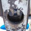
Nakedanvil - Grant Sarver Posted June 29, 2009 Share Posted June 29, 2009 (edited) Beaudry is my all-time favorite mechanical hammer. I'd sure like to hear of your progress. Looks like a great project. I've had a 125 and a 250, wish I still had them, well I wish I had a lot of hammers that I once owned. Funny that they have the anvil turned 90. Lacking any crack or breaks I think you got a diamond in the rough. Can't quite tell from the pictures, but I believe that one has the clutch inside the flywheel, almost sure. That means it came from the factory with a motor. Not sure if it was supposed to have a tensioner, might just swing the motor to tension the belt. Edited June 29, 2009 by nakedanvil Quote Link to comment Share on other sites More sharing options...
Nakedanvil - Grant Sarver Posted June 29, 2009 Share Posted June 29, 2009 No, the anvil bolts down and then the frame bolts down. You don't "remove the anvil from the hammer" you have to remove the hammer from the anvil. the anvil is shaped like a top hat with a bolt flange on the bottom. Quote Link to comment Share on other sites More sharing options...
Will. K. Posted June 29, 2009 Author Share Posted June 29, 2009 The hammer is just sitting on the slab, I beleive the current anvil orientation is just how it ended up after unloading and moving the hammer into its current location when the current owner purchased it. I inspected the frame for cracks and didn't see any but I suppose under all that peeling paint there could be some issues. There has been a repair to the arm that comes off of the clutch but it appears to be an old repair but the rest of the hammer looks to have been well taken care of when it was a working hammer. There is a hole for a ~1/2" bolt tapped in the frame that I'd rather wasn't there. It looks like it was used to mount a guard or hang a tool but like the clutch arm repair appears to have been there a long time. I see Beaudrys for sale so infrequently (especially close to my location) that I figured I'd rather take a chance on this hammer than take my chances finding one for sale in 10-15 yrs. If nothing else it will give me an interesting example of engineering to study. These are some neat machines. Quote Link to comment Share on other sites More sharing options...
Frosty Posted June 29, 2009 Share Posted June 29, 2009 Nice score! Bob Bergman might be able to help you out with parts, manuals, advice, etc. he rebuilds all kinds of power hammers. Postville Blacksmith Shop - ornamental gates and railings, furniture, tools for the blacksmith trade and subcontract forge work. I recon the anvil is rotated 90* simply because he never got around to getting it set up, not because of some mistake. Frosty Quote Link to comment Share on other sites More sharing options...
Will. K. Posted June 29, 2009 Author Share Posted June 29, 2009 It does have what I believe, from seeing several old ads, are the factory motor mounting brackets, I'm not sure if the motor is original. Some more pics below. Quote Link to comment Share on other sites More sharing options...
Will. K. Posted June 29, 2009 Author Share Posted June 29, 2009 I always meant to check that place out when I was going to school down in that part of the state but never got around to it.Bob Bergman might be able to help you out with parts, manuals, advice, etc. he rebuilds all kinds of power hammers. Postville Blacksmith Shop - ornamental gates and railings, furniture, tools for the blacksmith trade and subcontract forge work. Quote Link to comment Share on other sites More sharing options...
SGropp Posted June 29, 2009 Share Posted June 29, 2009 I have a #7 [200#] motor driven hammer just like that one. Great machine ! Send me a PM and I can arrange to send you a copy of the factory literature for the cost of the postage. For some reason,the way they were set up from the factory , bars worked along the length of the dies would run into the motor mount. I set mine up with the motor mounted on top. I used a 7 1/2 hp 1725 rpm single phase motor with a 2 to 1 reduction via a jackshaft to match the 850 rpm of the original motor rpm . The clutch seems to be lubricated with the oil that seeps out from the back end of the top main bearing. I use way oil through a drip oiler set for a pretty good flow. This seems to be right as my hammer has very good control and I do a lot of hollow tapered forgings on a set of flat dies. The anvil bolts down with 2 bolts from the foundation with access through oversize holes in the base of the frame . The frame has to be dropped down over the anvil block and is bolted down with separate bolts. Make sure the die keys in the ram don't stick out so far that the key hits the ram guides on the up stroke . Keep the rollers and tracks inside of the ram swimming in oil . Great score ! How much did you pay for it ? Quote Link to comment Share on other sites More sharing options...
SGropp Posted June 29, 2009 Share Posted June 29, 2009 My Beaudry was set up with matching top and bottom insert dies in a tool making factory in Mass. I got all the inserts as well as all the product samples of the tools it was set up to make; mostly star drills , pin punches ,hooks and pry bars. I had to torch out the big dies that held the inserts out of the sow block and ram, they were stuck so tight and I wanted to fit flat dies in the hammer. I got a set of both drawing and combo dies with the hammer . I had Bob Bergman make a set of new rollers and new flat dies . As I recall there is no lengthwise taper in the dovetail on the die, just in the ram and sowblock dovetails. Mine has short keeper pin in the center of the ram dovetail and the top of the upper die to help keep it in position. There should be a heavy solid idler pulley with a bronze bushing and oil hole mounted on an arched slotted bar on the motor or motor mount to tension the top side of the drive belt. Good luck on getting it set up and running . Quote Link to comment Share on other sites More sharing options...
Will. K. Posted June 29, 2009 Author Share Posted June 29, 2009 I've been pondering using a vfd to slow down a new 1750 rpm motor to the required input rpm. I was thinking it might be nice to slow down the motor even more in certain instances. Since its likely going to be a few years till its set up I figure I can keep an eye out for deal on a new motor and a vfd. A jack shaft would certainly be simpler and cheaper though. Are you running v belts from the motor and between the jack shafts? Quote Link to comment Share on other sites More sharing options...
Nakedanvil - Grant Sarver Posted June 29, 2009 Share Posted June 29, 2009 That's a beauty all right. You gonna have more fun than a hound dog in a manure pile. Beside the obvious stuff, most people will tell you to inspect the rollers and their tracks. I used to keep rags stuffed in the bottom and kept them saturated with oil. Worked pretty good that way, all the oil ran down to the rags when it sat and then when it was running the linkage would squeeze out enough oil to keep things lubed. My "hill-billy" lubricator! The first Beaudries I ever saw were in a spring shop. The old guy there really knew his stuff. 300# hammers were used for drawing tapers on truck leaf springs. He had these set up at about 350 BPM! Worked great because of the infinite adjustability of these hammers. The stroke was set very short, I'd say the ram went up and down 4 - 6" is all. He kept the spring particularly tight to a accomadate the rest. The 300 pounds gave the penetrating blow he needed for that heavy spring steel, but he still had the speed he needed for drawing. Cool! No other hammer is that versatile. Fantastic guide system too. Quote Link to comment Share on other sites More sharing options...
Will. K. Posted June 29, 2009 Author Share Posted June 29, 2009 It would certainly be easier to make extra dies if the taper was in the sow and the ram rather than on the dies. I'ld eventually like to purchase or make a set of flat dies for it. Do you have any pictures of the idler pulley assembly? I'll have to double check with the seller to see if that might be floating around somewhere in his shop.There should be a heavy solid idler pulley with a bronze bushing and oil hole mounted on an arched slotted bar on the motor or motor mount to tension the top side of the drive belt. Quote Link to comment Share on other sites More sharing options...
Will. K. Posted June 29, 2009 Author Share Posted June 29, 2009 The rollers looked good from what I could see but I didn't have a chance to inspect the roller faces contacting the elliptical tacks. I didn't see anything alarming with the elliptical track in the ram and there was lots of dried up oil/grease in there which I figured were good signs. The spring arms also looked good. Overall I didn't see any clear signs of abuse or misuse on the hammer. I like the rag lubricator idea, I wonder how a sponge would work. Quote Link to comment Share on other sites More sharing options...
Nakedanvil - Grant Sarver Posted June 29, 2009 Share Posted June 29, 2009 (edited) SGropp: S how you got yours set up? I had my big one set with a long stroke and "loosie-goosie" on the springs. 'Course I had the speed under 200 blows too. It's nice to be able to lay on the treadle and still turn the work. IMRHO Aren't you up kinda late? Edited June 29, 2009 by nakedanvil Quote Link to comment Share on other sites More sharing options...
patrick Posted June 29, 2009 Share Posted June 29, 2009 Will, Another person you might want to contact is Jim Fectaeu. He can be reached through the forgemagic.com forum. He broke the spring arm on his Beaudry last year and with the help of Steve Parker and Ralph Sproul was able to get new ones forged and machined. You might want add their notes on the process to your literature in case you run into the same problem. By the way, Bob Bergman should be able to give you any help you might need with rebuilding this hammer. He just did some machining for me on my 300 lb Bradley. How far are you from Beloit, WI? That is where I'm at. Patrick Quote Link to comment Share on other sites More sharing options...
Will. K. Posted June 29, 2009 Author Share Posted June 29, 2009 I'm in Menasha up around Appleton/Oshkosh, I think I'm about 2 1/2 hrs from Beloit. What type of Bradley are you running? Are you the patrick that was selling a moloch hammer last winter?How far are you from Beloit, WI? That is where I'm at. Quote Link to comment Share on other sites More sharing options...
SGropp Posted June 29, 2009 Share Posted June 29, 2009 I used a matched set of cogged v belts from the motor to the jackshaft pulley. The jackshaft is 1 5/8 '' to fit the flat belt pulley that was on the original motor. The jackshaft runs in a pair of heavy duty pillow blocks. I made a new motor mount that sets the motor up on the top of the frame where it's all accessible but out of the way. The mount is fabricated from 3/4'' and 1'' plate using the original factory bored and tapped holes to attach it to the frame . A magnetic starter is mounted front and center just below it. I spent the time and money to make a proper guard over the jackshaft and big flat belt out of angle iron, flat bar and expanded mesh. This provides visual access to the workings and a couple of ports allow the various lube points to be easily reached. The open free running belts on a machine like this are a serious hazard . The guard is attached to the frame of the motor mount or factory original tapped holes in the frame. I don't like the practice of drilling extra holes in these beautiful old machines and cobbling something together '' to get 'r done and working'' Once you start working on one of these old machines you get a sense of the craftsmanship and ingenuity of the original builders ,which should be respected. We are professional metal workers ,right ? If rebuilt properly and handled with care, these hammers should give at least several more generations of service. [end of rant ] My hammer is painted a very dark gray or black, I suspect this is the original color. The front of the ram was painted white, which I think was done to give a light background to check the profile of the work in the tool forge. Mine is set up as well with pretty much maximun stroke and not to tight on the spring tension. This seems to work pretty well for open die work, swaging and short top tool operations. I'm not sure of the speed ,but it's probably around 225 bpm at full throttle. I've got just under $12,000 in the machine including shipping all the way across country to a remote island, foundation, riser, crane time , new motor, mag.switch and power train, dies, keys, rollers, bronze guides, guard ,electrics and hired labor. Plus 8 months of my ''free time '' from when I located it to when it was back at work paying me back. I'll try to post a couple of pictures later. Quote Link to comment Share on other sites More sharing options...
ThomasPowers Posted June 29, 2009 Share Posted June 29, 2009 What are the failure modes in moving it? What is your previous experience moving heavy fragile items? What is the cost of a rigger? Moving equipment is NEVER a time to skimp on things! Especially time! Slow is good as you can keep the ammout of energy in the system low enough that if anything starts going wrong it just stops. Quote Link to comment Share on other sites More sharing options...
Will. K. Posted June 29, 2009 Author Share Posted June 29, 2009 I don't like extra holes drilled in equipment. They usually look bad and in cast iron don't like the extra stress concentrations they cause. The current owner has experience moving large & heavy machines and has a crane to help get it on the truck. I'm going to hire a local trucking company to go pick it up and I'm planning on hiring a rigger/crane service to unload the hammer once it gets by me. The biggest thing I've moved before was my large lathe and a free standing rotary metal shear. The color under the peeling paint on this hammer is a dark grey/flat black, I'm not sure if its a coat of paint or a primer/undercoat. I'll probably have about the same $ in this hammer by the time its all rebuilt and set up. Quote Link to comment Share on other sites More sharing options...
ThomasPowers Posted June 29, 2009 Share Posted June 29, 2009 GREAT, most unlikely to see a posting in the prayers section for you! I had a friend once who bought an in service 250# LG for $450, he borrowed a rock truck to haul it in and when he got back he planned on tipping up the bed until it slid in place. Well he tipped it beyond the angle of repose but it wasn't moving so he climbed in the bed to see where it was hung up. It shifted and he teleported from the bed to the roof of the truck cab. I literally did not see him cross the distance! Then he called a semi wrecker and for about $50-100 (been a while) had it safely unloaded and set up. Quote Link to comment Share on other sites More sharing options...
Judson Yaggy Posted June 30, 2009 Share Posted June 30, 2009 If anyone is interested, Steve Parker will be the featured demonstrator at Jim Fecteau's shop for the Fall New England Blacksmiths meet, featuring Steve on the Beaudry that he forged new spring arms for. Check out the NEB website for details. Quote Link to comment Share on other sites More sharing options...
patrick Posted July 2, 2009 Share Posted July 2, 2009 Will, I am the same Patrick that was selling the Moloch last year. My Bradley is of the upright guided variety, that is to say it is a helve hammer, but it is configured such that the ram is guided and therefor the dies are always parrellel. If you look through the old photos on forgemagic.com in the "Patrick Nowak" folders you can find picutures of the hammer and it components. Patrick Quote Link to comment Share on other sites More sharing options...
Recommended Posts
Join the conversation
You can post now and register later. If you have an account, sign in now to post with your account.