jwmelvin
Members
-
Joined
-
Last visited
Everything posted by jwmelvin
-
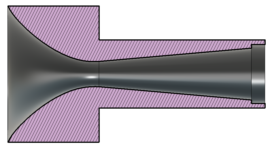
I agree you can put together an entrance section, but the expansion zone from a narrowed waist does not seem likely in that regard. To be clear, this is a schematic of my inducer cross section (I did not make it to this exact spec, just went for the most gentle expansion I could and a generally smooth compression):
-
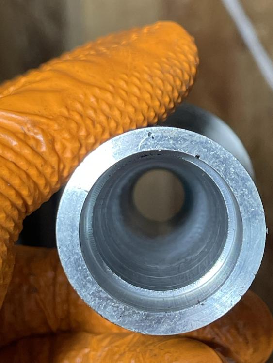
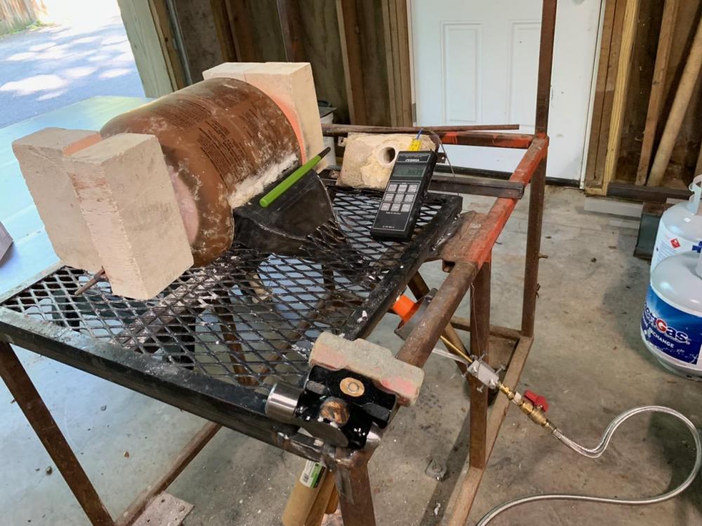
After my forge sitting idle for a couple years, my sister asked me if I could make her a ladle, so with a purpose, I revised my forge. The 3D-printed air intake was mostly fine when the forge was running and pulling in cool air, but could overheat when the flow stopped, despite sitting lower than the forge body. So remaking that was my task. The plastic cone seemed to work well for mixing, but there was some discussion on this forum about venturi-type inducers, which use a narrowed area after the gas orifice to accelerate the flow and create a lower-pressure area at the opening to draw in more air. That was my target. I have a lathe with a taper attachment, so I used that to machine an aluminum inducer. It's a really difficult task to get in to such a narrow opening (long boring bar, which is subject to chatter), but I just did the best I could with the tools I have. I matched it to the same mixing tube I was using before, which is about 0.8-0.9" ID I think. The expansion zone occurs over about 3 inches, something like 10° included angle. The air entrance (compression) zone: The expansion zone: The burner parts (though missing the centering plug that holds the gas tube in the tube with air openings): A bench test, using the nozzle on the mixing tube: In the forge, it still runs the ribbon burner. Seems to work pretty well, and now it won't melt. I'd consider adding some swirl-inducing features, but went with this for now.


-
-
Thanks AFB for the mention. I did create my ribbon burner using a 3d-printed, burnt-out mold/core. I posted it here. The method worked really well; vibrating the mixture let it sink into the mold easily. Like Mikey says, a round configuration would be better for the flow, but I made a nice transition to expand the flow from the mixing tube to the ribbon. That's shown in the thread AFB linked. It seems to work quite well. I continue to believe that not wasting the flow's energy is important, so sudden transitions and turns are best avoided. I know frosty likes them for mixing, but my approach doesn't seem to have an issue with mixing. My ribbon is big and I'm still thinking about a smaller one. Making the expansion with a round shape may be harder than rectangular.
-
Vibrating worked great for me, with 3 mm cores. The refractory sunk in like magic. I used an offset weight on an angle grinder to vibrate, so pretty high frequency. I wasn't using Kast-o-lite though, I used Wayne's refractory #2, which doesn't have the fibers or large particles of KOL.
-
AFB, thanks for continuing your work and posting about it. Seeing the venturi tube made me think. I'm still not clear as to the role of the throat, in that it accelerates the flow but then expands the flow right after that; such an action will lose energy compared to just flowing through a fixed diameter, so there must be a point. Perhaps the reduced pressure at the throat is what induces more air flow from the ambient pressure around the entrance. Or maybe there is something about a reduced diameter that allows the gas jet to impart more momentum to the induced air flow. Anyhow, I did a bit of reading and came across this study, which seems pretty relevant to our purposes. Have you seen it? One point I found interesting is that the optimum inducer nozzle design depends on the configuration of outlet ports (i.e., the back pressure created by an array of outlets, which we call a ribbon burner). So I will probably work on inducer design more now that I have settled on an outlet block that I like.
-
I soldered some brass fittings with plumbing solder and it has been working fine. But if another option is easier, I’m all for it.
-
Thanks. I did order the flux and solder AFB recommended. I was trying to figure out the difference from my plumbing solder, which has silver (1-5% I think?).
-
Is the idea of brazing rather than soldering that you benefit from the higher strength? Or the higher temperature capacity?
-
Aerodynamicist commonly use 6° expansion as the limit, which is a little more aggressive than 1:12. But in that range. https://www.grc.nasa.gov/www/k-12/WindTunnel/windtunnel_report.html Look at figure 9 here (5-6° for optimal pressure recovery); pretty interesting study: https://ntrs.nasa.gov/archive/nasa/casi.ntrs.nasa.gov/19720020645.pdf
-
Yea, my folks live in Hawaii, on the dry end of Molokai, and the giant centipedes are an interesting aspect of life there. They are fast.
-
Good point, thanks. I put the thermocouple in because it seemed like it would possibly give useful info, so if it can help me repeat conditions that's great. I've been a little tentative to run more than 10 psi so far, but I will do so next time I fire it up and see how things go.
-
Thanks. Knowing that your forge takes something like 20 psi is helpful; I didn't figure you would be able to tell me what I will need in my forge. I have never forge welded so that's (a big) part of the problem. I've only had my forge hot a few times. While I have a thermocouple, it seems to take a while to equalize in temperature and I'm not sure how much to trust it. It would be super helpful to work with someone in person; I will try to get to a local meeting to make some contacts.
-
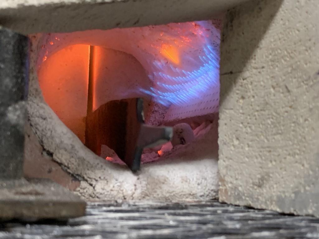
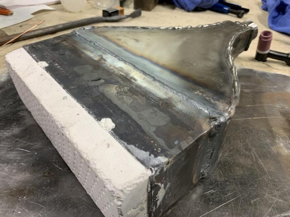
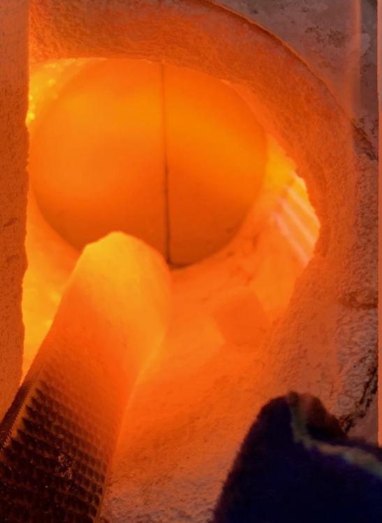
I welded my plenum together, which seems to help it maintain a stronger flame (no leaks): Here is the ~6.5 psi startup flame: Once warm, a 10psi flame burns a bit off the block: There were no issues running at ~2psi. Oh, I'm curious about what I might expect for being able to get to welding temperature. My forge volume is ~300 in^3, and I'm using something like a 3/4" burner (the mixing tube is larger ID than a traditional 3/4" pipe). Any thoughts as to pressure I might have to run at the gas jet? I.e., is 10 psi typically enough for this sort of thing, or would you generally expect to go higher? I know each burner-forge setup is different so what my setup needs will be different from yours, but having some examples and ballpark ideas would really help.

-
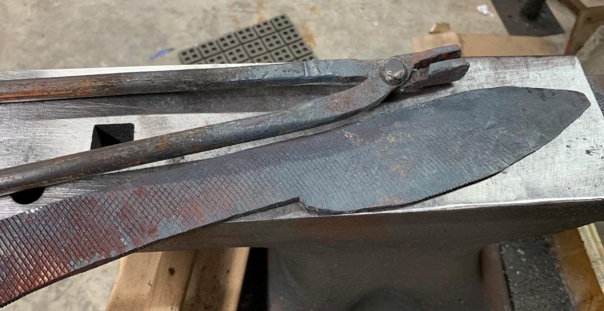
I ran my forge for a few hours yesterday to see how the ribbon burner did. It worked, though still needs some tweaking. I assembled the tongs that I had started the other day and used them to play with an old rasp to get to know the process for shaping a blade. It is definitely going to take some time to develop the necessary skills. :) Oh, you can just barely see how I radiused the edges of the anvil next to the step, for about 5-6" towards the heel.

-
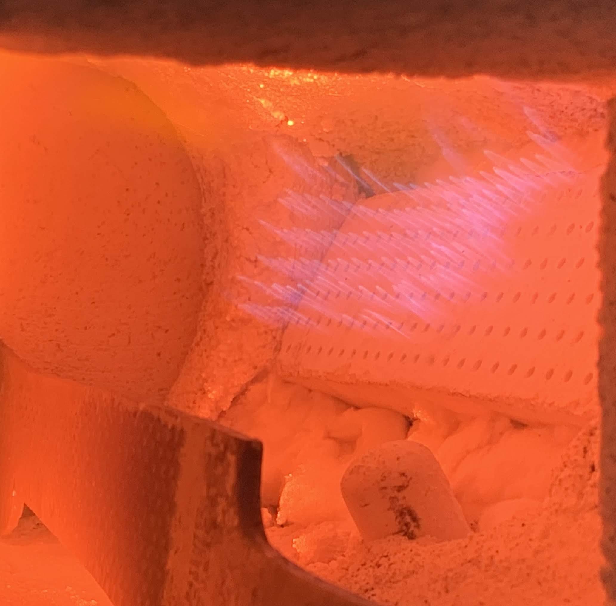
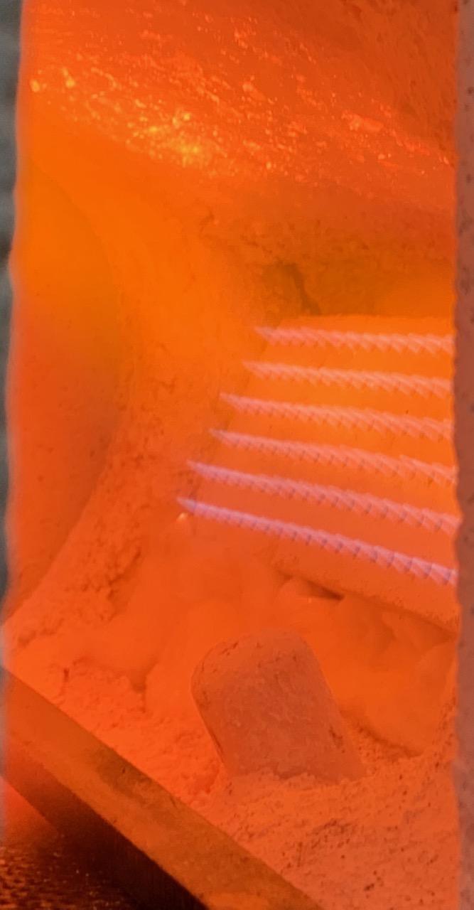
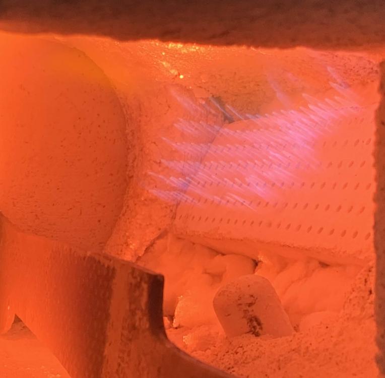
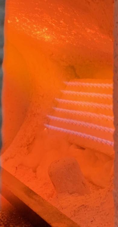
I rotated the forge a bit so that the burner enters at an upward angle, to help keep heat off the plastic inducer. It seems to work fine that way, as the mixing tube did not heat up at all during operation over a couple hours. The ribbon nozzle certainly works but I'm not sure it's working as well as it could. I was seeing ~1700 ºF while running at ~7-8 psi. The flames were generally pretty short and there was a lot of secondary flame, so I guess rich. At times the flames lengthened out to how I've seen them before. I think my taped-together plenum is leaking so I need to work on that. I will probably just go ahead and weld it together. It seems tough to get sharp pictures from my phone but here's one of the flame size and one of the secondary flame: I should add that there were no issues with backfiring, but I didn't try to run it down to super low pressures either.
-
-
Ah, got it; handheld cylinder. A needle valve modifies pressure, but does so as a function of flow rate. So it may be valid to approximate the jet pressure as the cylinder pressure when one uses such a small orifice and runs the needle valve fully open.
-
I was just curious why you would be discussing full cylinder pressure.
-
That’s an interesting idea. Perhaps tough to tune but with small enough jets maybe possible.
-
Two thoughts: (1) seems reasonable to run a regulator so perhaps we’d end up with a more reasonable hole size at, e.g., 5 psi; and (2) is the idea with a long tube that you are using the length to create a pressure drop, or that the length conditions the flow in a desirable way?
-
Aren’t the threads different? Did you adapt it somehow?
-
You do want a box to hold the KOL while it sets. I’m just encouraging you to think about how to get the KOL into the box as it is difficult to cram into a small space. It doesn’t flow much (depends on hydration). I was thinking: cover floor, place bottom panel of form over KOL, place side panel on bottom panel, cover panel with KOL, flip up to push against side wall, place other side panel on bottom panel, cover with KOL, flip up to push against other side, the cover top panel with KOL and place against roof. If the top panel overlaps the sides they will hold it up.
-
While a flow regulator is a fixed-pressure regulator, it follows that with a needle valve; so it can regulate just as well as an adjustable pressure regulator.
-
Definitely make a form. It is frustrating to try and shape it by hand. It’s not easy to get it in the thin form, so think about assembling the form as you fill it. Like plaster one wall then press the form against it as you move to the next wall. If you make the form I don’t think you will need any attachment between the KOL and bricks.