Hofi
-
Posts
1,086 -
Joined
-
Last visited
Content Type
Profiles
Forums
Articles
Gallery
Downloads
Events
Everything posted by Hofi
-
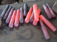
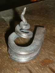
From the album: Hammers made Feb. 2007
-
IForgeIron Blueprints Copyright 2002 - 2007 IFORGEIRON, All rights reserved. BP1014 Bloomery Process by Mattias Zwssler This article that explains the ''bloomery process'' was written for the IForgeIron readers by: Matitias Zwissler Engineer for Metallurgy 58256 Ennepetal Peddenode 3 Germany Phone 02333-602920 Mobile 0137 5244 992 He spend most of his time on this subject and forging knives and mosaic pattern welding, and demonstrated the whole process twice. Every one that want to have more explanations is invited to call or write him and will be happy to answer questions. Bloomery furnace + the process Origon: beginning of the iron age Purpose: reduction of iron ore to iron. Oven design Vertical shaft 12x12 '' the base and the chimney 8x8 height approximately 4' Ingredients : iron ore (any iron oxide) scale will do. But not (sulfuric ore fes2 ) charcoal +air In total 70% 12 kg iron oxide in this case scale 15% sio2 quartz sand 15% caco3 kalk Air 180 litter a minute with a pressure of 0,5 bar 7.5 psi Process time 8-10 hours The furnace is built out of heat withstanding brick sand a ceramic pipe out of allu oxide or any other ceramic material the od of the pipe is 1.5-2'' Drawing is attached the ''blowpipe'' seats in the base construction at i20 degrees before the last brick of the ''basement'' Starting the furnace Fill in charcoal up to the level of the blowpipe and ignite fire then fill it up to the top with charcoals put the air on and on top of the charcoals put on cup of the ingredient mixture, wait until the charcoal is burning down one layer of bricks you fill it up again with charcoals and on top one cup of the scale ingredient mixture and repeat again and again for 8-10 hours. Chemistry Air +charcoal o2 +co=co+co2 Oxygen and charcoal react to carbon monoxide + carbon dioxide. At the temp of 1100 and more degrees c 2100 degrees F, we will have only co carbon monoxide which is the reduction gas. The process is called boudouard process. Ore reduction Fe2o3 +co ----->feo+co2 Feo +co --------> fe + co2 ( gas)----> that lives into the air The bloomery furnace reduces ore to iron in the ''chimney'' and in the ''basement'' the iron particles are fire welded to a ''bloom'' Tips and tricks Break the iron ore into ''powder'' Break the charcoal into 1'' particles Add the minerals (sio2, caco3) to get an easy smelting slag By looking into the pipe you can see the temp you have to maintain a temp of 1200 degrees C, 2200 f Physics of the ''bloomery'' furnace Reducing iron oxide by diffusion controlled reaction with co2. The ''speed '' of diffusion is a function of the temp and time and the surface of materials. The product The result is a spongy piece of iron with inclusions of charcoal, ore and dirt. It has to be forged out and fire welded on the anvil better with a striker. Hope the process is clear. Mattias Zwssler Thanks to Mattias Zwssler that gave me, showed and guided me, along this beautiful process and wrote the information for IForgeIron. Uri Hofi Kolbermoor Conference Germany Bloomery furnace Smelting (wooz) by Mattias Zwssler This article that explains the ''bloomery process'' was written for the IForgeIron readers by: Matitias Zwissler Engineer for Metallurgy 58256 Ennepetal Peddenode 3 Germany Showing the raw material and the final product, the wooz, and some samples forged as a test. Building the furnace, the air blast ceramic pipe, and the compressor. Crushing the charcoal to smaller pieces to get a bigger surface and getting more heat with less air. Fill the furnace half, put in the pipe, and turn the compressor on and fill to the top. On the top put a full serving size spoon fo the crushed "scale" iron oxide and the additives. IRON OXID 70% 12 kg QUARZ SEND SiO2 15% 2 kg LIME (CHOLK) Ca Co3 15% 2 kg From this amount we get at the end of the process 40% - 50% steel to forge. The process takes 8-10 hours. While burning the charcoal it is sinking down. When it goes down on brick, we fill it up again with the crushed charcoal and on top one serving size spoon of the mixture. After 8-10 hours we start the process of opening the furnace from the bottom. This is done in the night and the show is spectacular. After the bloom is out it is taken to the anvil to forge it with two strikers to squeeze it a bit because it is spongy. Then cut it to the wanted sizes of pieces and it is then forged with the air hammer. Cutting to the desired size pieces and forging to get the steel ready for multi-layers forge welding. The process is a reduction process. BEST REGARDS URI
-
IForgeIron Blueprints Copyright 2002 - 2007 IFORGEIRON, All rights reserved. BP1013 Tungsten Tools by Uri Hofi I saw that there is some interest about the subject so I have decided to make a small Blueprint about. Box with tungsten bars that were collected and brought to me by my younger students from the exercise of tank (armored) combat training fields. This is my source of tungsten. The other source is from the factory that produces the tungsten for my experiment (free of charge) Two types of bars that I use this are from anti tank shells found in the fields. One big OD 11/2'' the other 11/8'' on both of them you have to put a milled steel mandrel other wise they will shatter when hammer or put pressure directly!! I put the mandrel with ''hot fit'' the specific gravity of the tungsten is 2.5 times more then steel and the shrink expansion factor of steel is 0.00000635 x temp f degrees x od or length in thou'' in 1850 degrees it is 1.2% the factor for tungsten is half ! So when I put the mandrel on the tool with the ''hot fit'' I calculate exactly the differences between them for the temp of 1500 degrees. And when the mandrel shrinks it holds very very tight. The beauty is that when I want to take it apart I heat it more and because the difference of expansion it will release and the tools will go apart easy. After I put the mandrel on I can catch the tool on the frizer and work it to the right measurements (on the lath or frizer you cut with ''vidia'' or ''carbides'' bits). You can see on the tool the marks of the frazing. The same I do with the smaller od tungsten. The finished grinded tools with the grinding belt grit 36 finished with grit 100. I have some other tools in other dimensions for different use With the smaller tool I punch chisel the hand hammer eye. With this tool I have punched more than 600 eyes. The bigger tool I use to punch chisel the eyes of bigger holes like axes. Hope every thing is clear Uri Hofi
-
IForgeIron Blueprints Copyright 2002 - 2007 IFORGEIRON, All rights reserved. BP1012 Making Hammer Handles by Uri Hofi A - Because I want a certain shape for the handles you can not get in the shop. B - I love to do it (before forging I was a wood sculptor) C - It is much cheaper (I shape 100 handles in a working day) The wood I use is mostly '' epea'' very hard and tough wood and hard ''maple''. Hickory is not available in Israel other wise I would use it. A carpenter which is a friend of mine cuts the wood to planks 1-1/16 x 1-3/4 x 12''. You can always buy the handle, but I like to produce and shape the handles for all the tools I forge myself. I start with marking the planks. The hard paper templates that I use for marking the planks. Marking with the help of the vise. The marked plank. Grinding the shape with a belt grinder (which I built ) with a new 36 greet belt !!!! The belt is turning upwards. If the belt is not new it will not ''eat '' the wood !!! The finished basic form. Braking the corners and rounding the upper part that goes into the hammer eye. Braking the corners and rounding the handle part. Grinding the grooves for the glue. Grinding the bottom end of the handle. Finished handle. With the hammer head on. After running with the 36 grit I go again with a 150 grit and polish. The grinder. The wheel is mounted on the motor that runs 2750 rpm the wheel is 9'' 0D the motor is 2 .5 hp you can not see in the photo the very big fan that extract away and out all the grinding dust. On this grinder I grind all the hammers chisels and punches that I forge. Very simple and strong and easy to work with. The process from the plank to the finished handle. A pile of finished handles. Thank you, Uri Hofi I glue my handles to the hammer with pu sikaflex 11 cf. U have to wait 24 hours and only then you can brush it clean. I never oil the handle before gluing process because the oil will release it from the glue there are hammers that I forge now 17 years with and they are not falling apart. Only after the gluing and brushing process is finished I oil the handle one heavy time with wd40 which is very good for and easy to use. Is A Very Strong And Elastic Polyurethane Glue Take 24 Hours to Set . Then I Brush it Out With Rotating Steel Brush The Brush Fibers Are 120 Thou. One Container Is Good To Handle 25-30 Hammers.
-
IForgeIron Blueprints Copyright 2002 - 2007 IFORGEIRON, All rights reserved. BP1001 Hofi Hammer Technique by Uri Hofi Photos by Johannes Angele How NOT to hold a hammer You sea on the fotos that when you hold the hammer tight the strain on the muscles. If you swing the hammer that way because the continuous strain on the muscles you will sure get in time tendonitis (hope i wrote it right) or what we call here tenis elbow When you hold it my way (you can see it on the other fotos in section 401 "the right way to hold the hammer") that there is no tension on the muscles. One thing more: when you hold the hammers shown in the fotos 1+3. When you raise the hammer you bring the wrist joint to it limit and you damage the wrist, if you hold the hammer the right way with the palm of the hand parallel to the anvil face there is no limit to the joint and therefore no damage. How NOT to hold a hammer How NOT to hold a hammer Why not to hold the thumb on the handle? 1 This way you stop the hammer from bouncing and get the advantege of raising the hammer with the reaction. 2 This type of holding desturbs you to raise the hammer. The thumb is still pushing down when you want to raise there is a contradiction in the posision.and you use much more energy to raise the hammer. 3 The most important one is the thumb there is a nerve called A-5 that goes all the way to the neck spine. While we swing the hammer in a forging day at least 20,000 times, the little reaction of the hammer hits the nerve 20,000 times a day!!!! After some time and this is what eventually you start to feel pain in the neck and you have troubles moving the head from side to side, and this is a non-reversable damage.. The proper way to hold a hammer. The proper way to hold a hammer.
-
IForgeIron Blueprints Copyright 2002 - 2007 IFORGEIRON, All rights reserved. BP1011 Dimple Technique by Uri Hofi For this we need a very simple tool, 3 pieces of 5/16 x 12" long round bar. Weld all the three together on one end. Put it in the vise when hot leaving 3/4" out the top of the vise. Bend the center leg one direction and the two side legs the other direction. Open the two side legs to the sides a bit and open the center leg from the other two, creating a spring like tension and an opening for the hot steel. You put the heated steel between the legs, level with the top of the vise, and close the vise tight. The final dimple done in one heat.
-
IForgeIron Blueprints Copyright 2002 - 2007 IFORGEIRON, All rights reserved. BP1009 Post Vise by Uri Hofi There are many ways to design the constructing of the post vise which is one of the most used tools in the forge. I want to show my construction how it is built, moved, and some of the use. General look of the vise The base is a 20"x20"x2" mild steel plate weighing 200 pounds. Two 4" wheel are placed on the front side in a way that the center of the wheels (the shaft) is welded to the upper part of the base plate and out and a little off ground. In the rear side both sides two little plates with 9/16 screw is welded. In the middle of the base plate there is a u shape post from 1/2'. Flat steel in the dimension of 8"x4" in the height you decide you want the height of the vise On top of the post a 1/2" 25"x12" plate is welded leveled with the ground and right angle to the part that is hold in the vise The vise is welded to the post and the upper plat and down to the post all the traditional screws that fasten the vise are gone and there is no screw or nut in the way!! The upper plate is used as a tray for tools that you are using at the moment and for many other uses, one of them I will show latter. Wheels The use of the wheels On the rear side center of the base plate a 1" pipe 6" long is welded. When you push in the pipe a 7/8" steel 4' long and you raise it the wheel are touching the ground and you can move the vise easy to the place you want it. In both ends of the rear side two plates with adjustable screws with lock nuts are welded. After you moved the vise and the floor is not straight or 100% leveled you adjust and level the base plate fasten the lock nuts and it will stable the vise in place. And they will never move when working. If it is too hard it is not comfortable to close easy the vise. The spring must be elastic and not too strong its duty is only to keep the vise in open position. Another look One of the use of the vise and the upper plate Some times you need to weld a simple or more complicated construction and you are alone no one to help you, the vise and the upper plate is very handy. You catch the bar in the vise on the plate you clamp a right angel and to the right angle you clamp the other piece of steel you want to weld, you can put it in a right angel or any angle. You want and then weld it. In this system you can weld very complicated constructions single handed. Some times when I work a lot with the vise and I do not want the closing handle to fall all the way down. Put a plastic tape around the handle both sides of the center and it will keep the handle in the center. Always I put rubbers on the handle near the limit button. This prevents noise when the handle is falling down. It is easier to catch the button and you do not pinch your self ! A little thing but I find it important. A look to the upper plate as a tray for the tools while working. There are many other uses to the system that will be shown on other blueprints. Thank you Uri hofi
-
IForgeIron Blueprints Copyright 2002 - 2007 IFORGEIRON, All rights reserved. BP1008 Rivets to Length by Uri Hofi I forge many type of tongs and I can not always get rivets to the length I need. I have to shorten the rivets to a specific length, so I developed a easy to use tool and a very pimple way to do it. D = Diameter of the rivet head A = Future length of the rivet from the center of the hole to the end of the tool B = Outside Diameter OD of the rivet stock less 15%. Shows the wooden tool How to make the tool Use a piece of wood 1 1/2"x13"x3/4". Drill a hole (D) for the OD of the rivet head. The center of the hole to the end of the tool (A) is the future length of the rivet. Cut with a saw or a disk a slot in the middle of the wood, to 11 1/2". With the saw again cut the bay for the rivet 15% narrower then the OD of the rivet (B). Shows the process The process 1 You push the rivet in the tool The tool will hold the rivet because it acts like a spring. (if it is made out of good wood) 2 You put it in the vice close not too tight 3 Cut with a very thin cutting disc 4 Take away from the vice and pull the "legs" to the side against the spring tension 5 The rivet falls into the box This is a little trick but it helps me very much. Uri Hofi
-
IForgeIron Blueprints Copyright 2002 - 2007 IFORGEIRON, All rights reserved. BP1007 How to use the Hot Cut by Uri Hofi Cutting on the HARDIE is an operation that We often use!! We use it to cut off a finished element. To prepare the steel for the next step or to incise the bar and proper it for a tennon. In many smithies they use two types of hardie and some times more. I use only one hardie for all the operations. I am going to demonstrate the three basic methods I use. THE TOOLS: ANVIL HAND HAMMER,HARDIE THE HARDIE Is forged out of a lorry rear axle and this steel is good for cold and hot cutting. The HARDIE is 3" high and 1 1/2" and more wide Ground sharp to 30 degrees FIRST CUT You lean on the hardie in the place you want to cut parallel to the floor and 90 degrees to the hardie. You hit easy with the hammer while rotating the steel the other direction from you ,until you get an even incision around. Then you hit harder while rotating until you get a very thin nipple connection in the middle. You hit with the hammer out the piece is falling and you see the cut. HOW WE DO IT The cut before demonstrated the possibility to have square cut on the two sides but some times we need that the near side will have a point and the far side will have a straight cut. We lean the steel on the place. We want to make the cut. We hold the steel again 90 degrees to the hardie and parallel to the floor and we forge a light incision around the steel again. We push the steel down 15 degrees (You remember that the hardie is 30 degrees) so we push down half of it, and continue hammering while turning until we come to the center. You can see that we get a cut that the far side is straight and the near one is a short point. We hit outside and brake the piece and we can see the final cut. HOW WE DO IT Some times when we cut we need the opposite that the strait cut will be on the near side and the point on the far end. Then we tilt the steel up 15 degrees and the hammer too to the same direction. Again we put the steel on the hardie on the place we want to make the cut. We incise the cut around easy. If you stop in the middle of the process depend on the depth that you are coming too this is a start of a tennon (you do not need the "blacksmith magician" The hardie is having many more uses may be we will speak about it in the future THANK YOU URI HOFI We go on forging and rotating until we get the thin connection and we brake it and get the final cut.
-
IForgeIron Blueprints Copyright 2002 - 2007 IFORGEIRON, All rights reserved. BP1018 A spiral from 20mm material by Uri Hofi We use here the heavy duty tool made out of the 1" square full steel. First bend Begin bend of scroll Continue bending Continue heat and bending Hammer close the spiral We can produce the same type tools for square material by using the hydraulic press or the air hammer. The finished elements and the tools.
-
IForgeIron Blueprints Copyright 2002 - 2007 IFORGEIRON, All rights reserved. BP1006 Hofi Tong Clips by Uri Hofi When forging and using the tongs to hold the steel, rotate move and change the position of the steel on the anvil the managing hand gets some times more tired then the hammer hand, when you have to hold with a good grip on the reins not to let the steel fall and to be all ways in the right position, a good and simple clip prevents the position. There are many types of clips some times to heavy and some times to complicate to forge. This is simple to forge easy to use and I forge it in one heat. The tools used are an anvil, hand hammer, anvil fork, hardie, belt grinder. Material is round steel 1/4" or 5/16" OD You point the steel out of the fork leg according to the size of the clip. You lean on the left leg of the fork and you hammer towards you on the other. You can see that I over lap the end of the steel to prevent it from colliding in the next step You lean on the near edge of the anvil and hammer down until you get the 90 degrees eye Lean on the far edge of the anvil hammer the eye towards you until you get a compleat eye and the" legs" are straeight in line with one another. You lay down the eye on the anvil and forge it flat to the OD of the steel. You can see how I straighten the element when the eye is in the prichel hole. Forging the final form on the fork. Cutting off the clip from the steel on the hardie. Grinding on the belt grinder to round the end. The use of the clip. The tongs are always desigened in a way that the clip is put on the rein from the narrow side (front) and is slides back wards the end of the reins. The "C" clip has existed for hundreds of years. My addition to the clip is the "eye" that makes the clip much more easy to use, hold and adjust. Assorted size clips. The little bowl on the anvil tray contains assorted size clips. This keeps the clips in one place so they are easy to use. Hope things are clear Hofi
-
IForgeIron Blueprints Copyright 2002 - 2007 IFORGEIRON, All rights reserved. BP1017 Decorative Element by Uri Hofi The decorative element on a candle holder point. The tool is the light duty tool from the RHS. The steel that we work with is 9/16" OD. First we forge the point to the desired length and point size. Then we put it in the tool and the right hole, close tight the vise, and with the rosebud, we create the form we want. Because of the clearance we gave when drilling the holes, the steel will be held in the tool very good and tight and will not move or turn. The finished element Other decorative elements and the vise tools (BP1016).
-
IForgeIron Blueprints Copyright 2002 - 2007 IFORGEIRON, All rights reserved. BP1016 Leg Vise Tool by Uri Hofi Some times we need to hold firm round steel in the vise bend or twist or both bend and twist. When you just hold it plain in the vise it will tend to bend turn and go out of the right angle (90 degrees) that we need and we have to ''fight'' to hold the steel. I have developed a simple tool to solve the problem and very easy to produce. We can produce the tool from square-- rectangle-- full steel bars or from rhs thick wall. Depend if you want a heavy or light duty tool. In this case one tool is full steel 1�square. The other one is RHS 1 5/8 x 3/4 1/8 '' wall thickness. Both are 18'' long Mark the middle and use a square to mark the line. We cut to the marked depth. Put in the vise when the cut faces down and with the rosebud heat and bend upwards Finished bend when the two halves meet and leaves 2 mm clearance The same with the RHS. The two finished bends. We have to remember to leave a 2mm clearance. Into the clearance we hammer a piece of 2mm sheet metal We close in the vise, measure the distance between the holes and center punch. Close with a �C� clamp the other side to prevent the sheet metal from falling out. Drill the 5/16'' guide holes. The tool will hold in this case 1/2''- 9/16''- 5/8''- 3/4'' round steel. To guide for the bigger holes we need a �guide hole�. 12.5mm 14mm, 16mm, 20mm When drilling the bigger hole, many times the bigger tap is vibrating when you start. There is a little trick to overcome the vibration. Take some pieces of paper, fold 3-4 times and put on the guide hole under the tap. Start drilling easy and it will guide the tap and prevent the vibration. You can do the same with a piece of cloth. tap = dril bit Do not use gloves. The finished holes. The same with the RHS Now we take two pieces of 5/16''X 6'' long and weld on the two sides of the tool to hold it on the vise after we took the pieces of sheet metal out. The finished tools again. Decorative elements (BP1017 and BP1018) and the vise tools
-
IForgeIron Blueprints Copyright 2002 - 2007 IFORGEIRON, All rights reserved. BP1004 Hofi Woop Tongs by Uri Hofi The name "WOOP" Tongs started when I demonstrated for the BAM at the meeting of 1998. I forged this type of tongs and the people could not understand to the last operation of the form how it works. Then when I made the last twist, I said ''WOOP WOOP" and instantly they were named "WOOP" tongs. Chisel/punch the hole Cut the steel to length (in this case 5/8 x14" to hold 2"square bar. Steel is 1045.) flatten a bit with the air hammer (after when chiseling the steel will not rotate) mark with a squared center punch (you can see the mark when the steel glares see also the system of marking (for 30 pairs of tongs x 2=60 pc). The gas forge, there are always 3 pc in the forge - one comes out - one goes in = progressive entry. 2 chisels and 6 drifts The tools: I never cool one chisel in water because if you cool only one chisel, it becomes brittle and brakes some times. To save time, I heat the stock and then punch the hole in one heat. I do not loose time for the cooling the chisel. The 6 drifts are allowed to fall into the cooling water below the prichel hole. From there they are put into the anti seize coolant and we continue the process. Chisel from two sides and finish on the aluminum. Drifting from two sides. The eye. For # 2" it is 4" For # 1 1/2" it is 31/2" For # 1" the steel is 9/16" OD and the distance is 3" The distance from the Center Punch to the end of Tongs is The anti-seize system. After I take them out of the water I put them into this cup. The eye with the prichel hole rosette (adaptor) to bring the hole to the same OD of the drift. The prichel hole is 3/4" diameter and this adaptor redeces the diameter to 3/8" so there is no distortion of the eye. Forging the reins and the side of the the jaws. Forge all the 60 pieces both sides to the correct same length (17.5" and 7"). The eye place must be always thicker than the reins and the other side, then when we rivet the two parts they touch one another only in the riveting area. The air hammer dies are 1 5/8" wide grinded according to the Hofi air hammer forging system (will come some times in the future BP) by this we can forge faster create and maintain the heat for a longer time and again finish the forging of the rain in one heat. The trolley which moves the finished parts from one station to the other. Now that the basic form is ready we can start and forge the jaws step by step. We stick the end of the measurement bar on the flat of the stock in the vice and measure 1 5/8" with the measurement bar. Hammer to the vice to 90 degrees. Turn clock wise 1/4 turn, measure to the measurement bar for 1-5/8" again and hammer towards you to 90 degrees again. Put on the v swage and with a v fuller correct the corner to be a nice 90 degrees corner. Lean on the other side of the anvil and hammer the metal towards you creating 30 degrees angle. The finished form to be flatted on the anvil. Heat up with the rosebud (many times I use the rosebud to get a higher heat in a certain point and faster). Lean on the near edge of the anvil on a sharp corner near the eye. Hammer down to the anvil when the managing hand is moving slowly down until the hand touches the anvil. Correcting the eye with the punch to renew and prepare the eye for the rivet. The final form. Now we are forging the last form before riveting. Long heat hotter near the eye. Cool the end in water just the far end. This is the water under the prichel hole that the drifts fall into when being used. Catch the anvil stage with the end angle that we forged before, and with the rounding hammer we create a horseshoe like form with raising the managing hand up. With a London pattern you can not do this. You will have to make a tool to put into the hardie hole to work with. Finish the horseshoe form on the end of the round beak of the anvil. The last touch. The finished form. Put one on the other to check. There is no left and right side, both are identical when they are made. Riveting. Heat the joint with the rosebud to release the rivet. Â Rivet released. Now the tongs are riveted but not symmetric. We have to bring them to a symmetric position by bending and twisting. We lock them in the vice when the joint rivet is hot and with that we align the reins. With the bending tool we bend them to be in line. Â Now we have to twist jaws of the tongs to the right 90 degrees and make them symmetric. To do it we use the vise grip and the adjustable spanner, the first to grip the other to twist. This is where I say "WOOP WOOP" Now we have to adjust the final fit to hold 2" square steel, for this we will put the tongs in the gas forge. The 2"steel is held with the hot tongs. Hammer to fit to the anvil. The fit is finished. Finished tongs. 10 pairs of a size. 30 pairs of 3 different sizes. The tongs will hold: flat steel thick flat 2'' pipe with a piece welded, 2''square, 2'' round, Many od materials that no other tongs will hold!!!!!!!! " THE MORE A TOOL CAN DO, THE BETTER TOOL IT IS. " The final photo is dedicated to all the tools that participated in the party (project). To me the making of these tongs was a party. The anvil on three legs with a tray that moves on a shaft to accommodate the tools needed for the project can of ez-lub, a bowl of water for the drift to fall in to cool through the prichel hole. On the anvil all the tools: the v swage the v fuller the bending tool vice grip adjustable spanner 2 chisels 6 drifts the adaptor in the OD (outside diameter) size of the drift and last and not least the hammer All the 30 per of tongs where forged in 35 hours . I hope that the long journey of this Blueprint is understood and clear, thank you for the attention. Hofi
-
BP1015 How To Use A Magnet As An Helper To Build Structures
Hofi posted a article in Uri Hofi Series
IForgeIron Blueprints Copyright 2002 - 2007 IFORGEIRON, All rights reserved. BP1015 How To Use A Magnet As An Helper To Build Structures by Uri Hofi To build a base for a 3000 year old jar for a privet collector. The finished stand. The forged elements. The use of a big magnet 4x6x1'' to aligne the and hold the elements in a ''right'' angle. The stand with the jar. Thank you, Hofi -
-
-
-
-

-
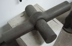 JOINT OUT OF 4'' OD STELL JOINT OUT OF 4'' OD STELL
 -
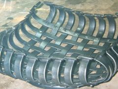
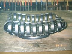
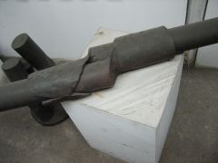 4" OD steel joined A 4'' OD STEEL JONERY I FORGED IN CARDIFF AT THE FIFI CONFFERENCE 1989 SLITED WITH A TUNGSTEN CHISEL WITH 3 STRIKERS
 -
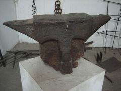 French Anvil FRANCH ANVIL DATED 1723 A FRANCH ROHSET ON THE SIDE AN ''MN'' MONARCHY NAPOLEON ON THE OTHER. FOND IN A JUNK YARD IN THE OLD TOWEN OF JAFFA
 -
-
-
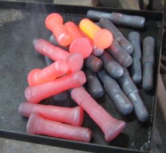
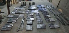
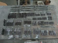
From the album: Chisels in production
Tools for Germany TOOLS FOR GERMANY IN PRODUCTION (THE STEEL IS H13 AND AIR QUENCHED)