lloe01
-
Posts
181 -
Joined
-
Last visited
Content Type
Profiles
Forums
Articles
Gallery
Downloads
Events
Everything posted by lloe01
-
The one where you said to ship the hammer to you :)
-
Frosty, I just got your joke I just got the phone call and go pick up the Star hammer tomorrow! Woohoo!
-

Working on my Mayer 25lb
lloe01 replied to lloe01's topic in Power Hammers, Treadle Hammers, Olivers
Dang! Forget the sandblasting. What a mess! I think I will just use degreaser and clean it that way. -
Working on my Mayer 25lb
lloe01 replied to lloe01's topic in Power Hammers, Treadle Hammers, Olivers
I was going to bag the crankshaft area and only blast below it. Most of the grunge is below that. The crankshaft on this is not split like the LG. It is completely sealed. But, I do think you have a valid concern. I will seal that area really well before doing anything. i really appreciate all the information you have given me, Frosty. thanks! -
Working on my Mayer 25lb
lloe01 replied to lloe01's topic in Power Hammers, Treadle Hammers, Olivers
I drilled the second rod end last night. I was going to install everything, but am going to do a little sandblasting to get all the layers of grease off the hammer. I just need to find time. Also looking for some rubber to go under the hammer once I am ready to place it in my shop. I found some one-inch thick rubber pad at tractor supply co. Can't find it online tho. It looked like a 3 ft by 4 ft. seemed perfect -
Thanks, guys! i do have that book, Frosty. i will look at it some more. Thanks, Augus7us! Larry
-
I have a chance of buying a Star 50lb for $1500. It looks great (sorry, no pics) and runs well. Except it doesn't have the correct dies. The top and bottom dies look to be 6" x 3". But they are not aligned directly with each other and only about 3" of each die hit. The top die is towards the center, but the bottom die is somehow shifted to the left. if I cannot get the correct dies, I don't see how the hammer will be worth the money. Anyone have spare dies for this hammer? Yes, I am still working on my Mayer 25lb, but this kind of dropped into my lap yesterday.
-
Working on my Mayer 25lb
lloe01 replied to lloe01's topic in Power Hammers, Treadle Hammers, Olivers
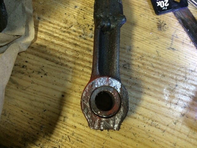
Pressed the bushings in and drilled an oil hole in one of the rod ends. Drilled all the way through the bushing, of course. That way the oil gets to the bolt/pin on the ram. Still have one more rod end to drill and install. I stopped for the night. I will drill the other bolt tomorrow night. -
Working on my Mayer 25lb
lloe01 replied to lloe01's topic in Power Hammers, Treadle Hammers, Olivers
Got the bushings in today. Yay :) -
Working on my Mayer 25lb
lloe01 replied to lloe01's topic in Power Hammers, Treadle Hammers, Olivers
I got a couple of Rod end bolts last Friday. They have 3/4" eyes and the ram has 1/2" eyes. I have ordered some 1/2 ID by 3/4 OD bushings to make up the difference. I went ahead and installed everything so I could see what it was going to look like.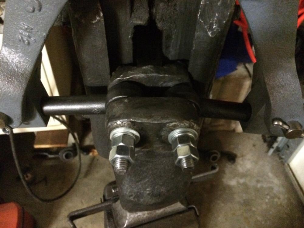
-
Very nice!
-
Working on my Mayer 25lb
lloe01 replied to lloe01's topic in Power Hammers, Treadle Hammers, Olivers
I replaced the bolts with pins and have the cotter pins in now. i have the ram raised one inch in order to take some measurements for Roger.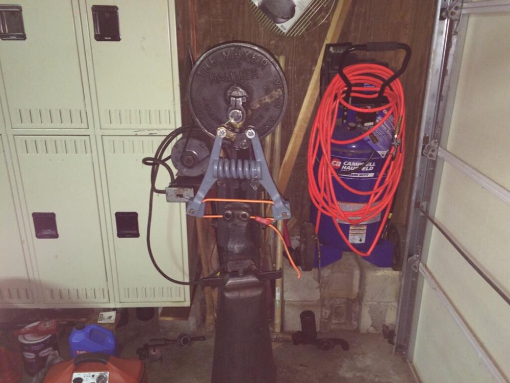
-
Working on my Mayer 25lb
lloe01 replied to lloe01's topic in Power Hammers, Treadle Hammers, Olivers
The long bolts are just until I was able to put everything together. The pitman does have a little movement on the shaft. Maybe the crosshead is pulling it backwards a little? -
Working on my Mayer 25lb
lloe01 replied to lloe01's topic in Power Hammers, Treadle Hammers, Olivers
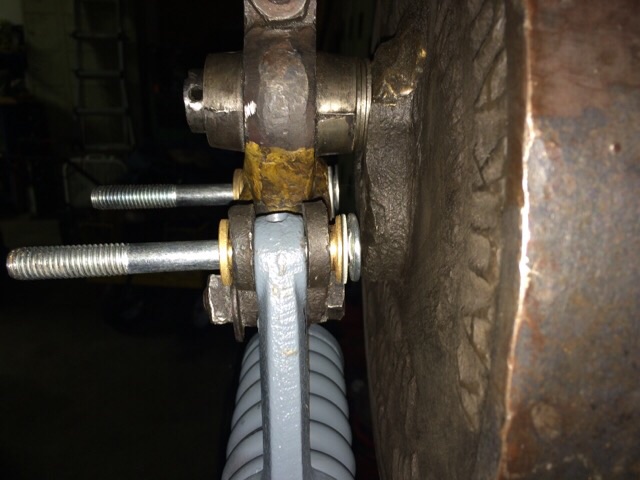
It put quite a bit of space between the bolts and the crankplate. The second photo makes it look like there is no space, but there is. Just a bad angle of the camera. It added some space between the spring and the crankplate too.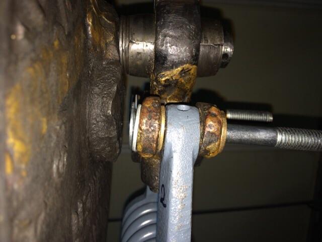

-
Working on my Mayer 25lb
lloe01 replied to lloe01's topic in Power Hammers, Treadle Hammers, Olivers
I placed several washers on the shaft and it is looking great. -
Working on my Mayer 25lb
lloe01 replied to lloe01's topic in Power Hammers, Treadle Hammers, Olivers
Thanks Frosty. I seem to take the more difficult option. That was pretty obvious once you mentioned the washer. I will put a washer in there to move the pitman forward. -
Working on my Mayer 25lb
lloe01 replied to lloe01's topic in Power Hammers, Treadle Hammers, Olivers
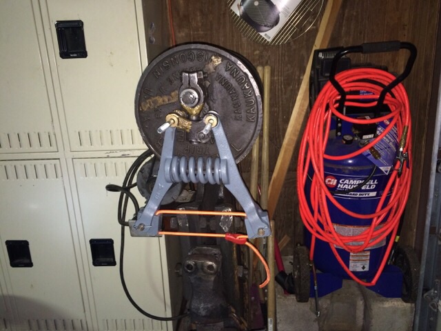
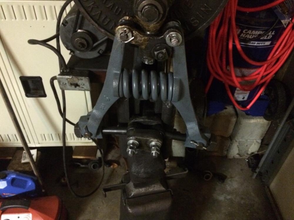
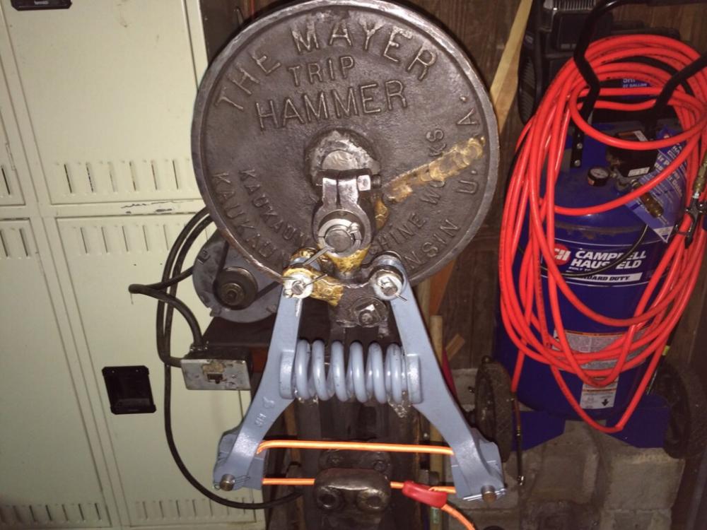
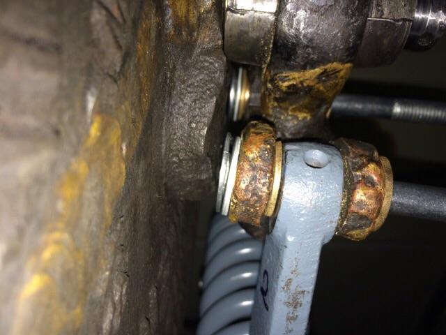
I have the Mayer in a corner of the garage, behind my motorcycles. There is a front shot of the hammer with the arm assembly on it. I'm using the bungie cord to keep the coil under a little tension. the next thing I need to do is get the measurements that Roger needs for the toggle links. Then grease and oil everything and see how it runs.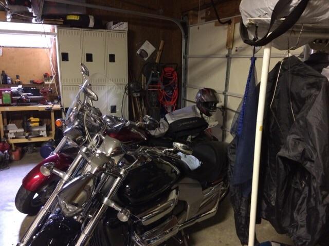

-
Working on my Mayer 25lb
lloe01 replied to lloe01's topic in Power Hammers, Treadle Hammers, Olivers
I placed the pitman and arm assembly on the hammer. When I rotated the crankplate, part of the crankplate face hit the bolt head. I am using a round head bolt and there was just no clearance. I went ahead and machined the bolt head from .23" down to .08". Now they won't hit the crank plate and possibly cause problems. Below are pictures of both sides. Notice the flat bolt heads and the minimal clearance.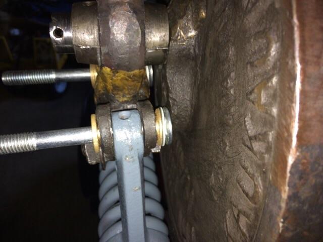
-
Working on my Mayer 25lb
lloe01 replied to lloe01's topic in Power Hammers, Treadle Hammers, Olivers
Here is what I have so far. The long bolts are just placeholders until I determine whether pins or bolts are supposed to go there.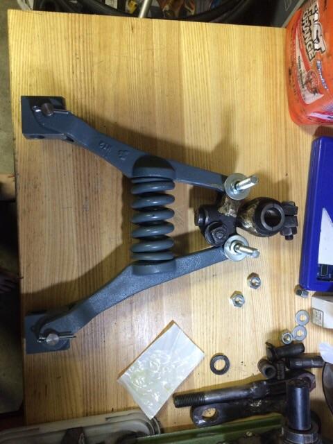
-
Working on my Mayer 25lb
lloe01 replied to lloe01's topic in Power Hammers, Treadle Hammers, Olivers
Roger sent me two knuckles. I am assuming he wants me to use two adjustable toggle links. Kind of makes sense, especially if he doesn't have the correct toggle link for the Mayer. -
Working on my Mayer 25lb
lloe01 replied to lloe01's topic in Power Hammers, Treadle Hammers, Olivers
Thanks Jeremy! That makes sense. -
Working on my Mayer 25lb
lloe01 replied to lloe01's topic in Power Hammers, Treadle Hammers, Olivers
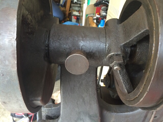
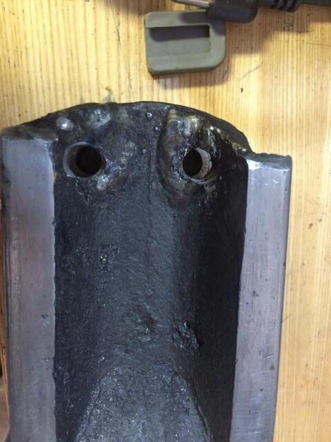
Yay, was able to drill out the 1/2 inch bolt holes for the ram. And my bushings came in. They are just a tad too large, but I can turn them down on my lathe. The flange is also too thick, but I can turn that down on the lathe also. i attached a pic of the hammer without the ram. Are the guides supposed to be roughly angled at the top or was this one "customized"? Also, what is this knob on the crankshaft do? I have turned it a few turns both ways and it doesn't seem to do anything.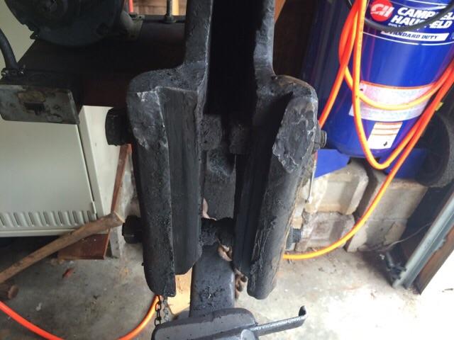

-
Working on my Mayer 25lb
lloe01 replied to lloe01's topic in Power Hammers, Treadle Hammers, Olivers
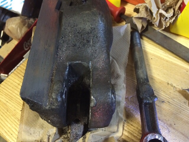
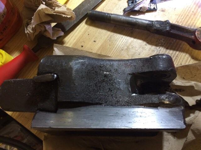
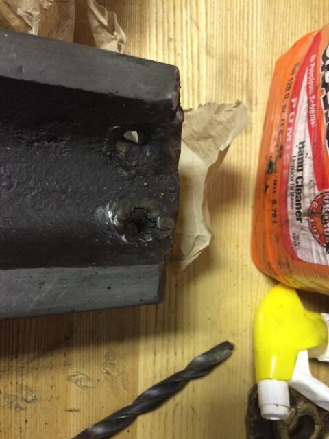
Frosty, I was finally able to get the ram off. There was a slight flat spot on the side of the crank plate that allowed me to lift the ram up and away from the guides. The guides are definitely not removable. I agree, the bolts that go thru the ram guides on this Mayer 25lber are there to stiffen the guides. It is one solid bolt that goes thru both sides, just behind the guides. i was finally able to cut thru the pins and remove the makeshift toggle links. Of course, I thought it would now be easy to to continue on at this point. But, nope, nothing is easy with this hammer. The bolt holes on the back of the ram are almost welded shut. I am going to have to carefully drill them out. Sheesh. Here are some more pics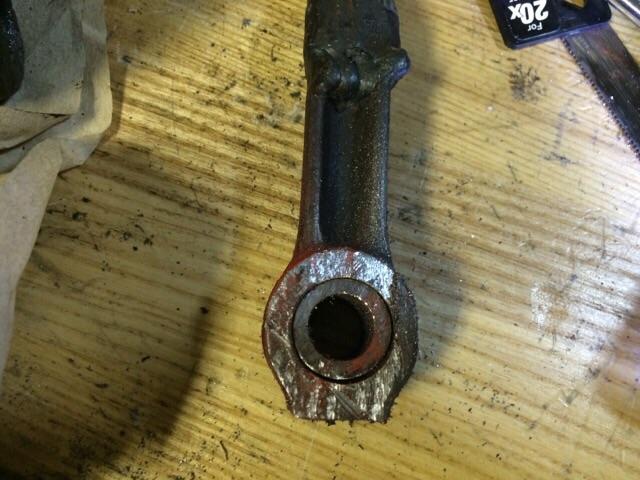

-
Working on my Mayer 25lb
lloe01 replied to lloe01's topic in Power Hammers, Treadle Hammers, Olivers
Frosty, that picture of the "flywheel" is on the www.littlegianthammer.com "resources" page. It is the parts diagram. -
Working on my Mayer 25lb
lloe01 replied to lloe01's topic in Power Hammers, Treadle Hammers, Olivers
Crank plate sounds good I'm looking around the bolts near the ram guides and cannot see any seam. I will loosen the nuts and see what happens. I hope the ram guide does come apart. If not, it makes it really hard to repair it if something breaks. I will see what I can do this weekend. Thanks for all the ideas and help, guys!