
knots
-
Posts
734 -
Joined
-
Last visited
Content Type
Profiles
Forums
Articles
Gallery
Downloads
Events
Everything posted by knots
-
Treadle Hammer Question
knots replied to wd&mlteach's topic in Power Hammers, Treadle Hammers, Olivers
The concept that I preposed is to to mount the planishing hammer on the back side of the frame. The rear mount configuration would provide two seperately functioning machines on the same base. That way both machines can be used without remounting or dismounting any component. The only change required is the position of the opperator. In extreme the circumstance of lack of space I suppose that the air hammer could be mounted on the TH ram . But it seems that solution would be less than ideal. In that case the air hammer could be mounted to the front or one side of the ram and a supplimental tool holder provided to the corresponding side of the TH anvil . This just seems a bit over contrived to me. Under those circumstancces I would choose to build a compact unit like MacBruces that would store easily out of the way when out of use. -
Treadle Hammer Question
knots replied to wd&mlteach's topic in Power Hammers, Treadle Hammers, Olivers
Sounds like you are a busy guy. Hang in there. Things will level out . Family, education ( yours and theirs), and blacksmithing are worth the effort. So far as the Planishing Hammer Idea is concerned, the idea is there, maybe a future need will arise. Looks like good progress is being made on the hammer. The total weight of my hammer ram/head is around 55 pounds. In order to achieve that I ballasted it with molten lead . I have heard of others who have used lead shot to achieve something like a dead blow strike. Are you planing adding weight ? One thing that I can say about mine is that it delivers a heavy blow, and the good thing about the weight is that the return springs do most of the work managing the weight. That is to say that it swings easily on the down stroke so there is only an upside benifit to additional weight. I would like to hear form others, who have built a Treaddle Hammer, how they ballasted theirs or even if not. One other thing - Take a look at the top front edge of my hammer head. I welded a 1 1/2" round bar to the front edge of my TH ram. This adds extra weight, but the real reason it is there is to use as a handle. This feature is especially handy if you have and use tooling fixtures such as Butchers . If you have a free hand It can be used to add power to the down stroke. -
My QT is made from a 40 pound tank I don't remember how much oil that I put in it but it should easily hold 5 gallons. I have quenched power hammer dies in it without any problem. For one off projects it handle most needs without over heating.
-
My small forge has a swing up door with a hinge designed with cam out action to keep the refractory from rubbing against the forge case as it swings up. The door cams out about 1/8Th inck just above the closed position. This gives a good seal when closed but provides opening clearance immediately when opening. My door handle is a thin wide bar that provides a large surface area for radiating heat to cool the handle. I tried other options before settling on this as a permanent solution . My other two forges are are larger pipe forges with flip up doors. I do find the cam hinged door to the the most convenient in use. Although these doors are used on the smaller forge I see no reason that the cam hinge could not be scaled up to a larger forge if desired.
-
Quench Tank Catch Basket. Here is mine.
-
Treadle Hammer Question
knots replied to wd&mlteach's topic in Power Hammers, Treadle Hammers, Olivers
Hey Teach After the above exchange I got to thinking about another project that has been on my back burner for a while. It suddenly occurred to me that the back side of the adjustable TH frame could be put to use. You are apparently one of a rare breed, I understand from your postings and images that you are a shop teacher, it occurred to me that this would be of particular interest to you. The idea is to use the back side of your TH frame as the foundation for a planishing hammer, The adjustability built into the frame is ideal for that application. I am currently sorting through my stock to see what materials I have to build my own version. I already have an old pneumatic scaler in a drawer some where so my first task is to figure out the configuration of the frame arms and their mounting detail. There are many examples of owner built machines but I like Mac's basic design and will use my scaler hammer as his ZIPMAX did. Thanks Mac. Currently I am looking at using a small hydraulic jack to raise and lower the anvil base. The main advantage to me is that adding the additional function to my TH will help preserve space in my crowded shop. In your case the doubled channel would provide the foundation for a robust unit. -
Or it could have been a ship's anvil. I have seen a few that had been cut at the waist and welded down some where aboard a ship. Then when no longer needed rewelded to the same or a different base after retirement. However I think that Jim is probably right since the joint is such a good fit and the weld really neat and well done. Most of the ships anvil re-welds that I have seen look pretty scabby and ill-fitted.
-
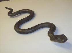
Youve just gotta like a creative re-adaptation such as this . First other thing that comes to mind now that you got us thinking about this is that Just maybe you could make a small down draft grinding table out of one. Thanks for sharing. Picture please.
-
Not laughing. Maybe crying. A chinese friend gave me a tin of some sort of salve that had a dragon on the can top. That was some hot stuff. You learn very quickly that if you use such a salve or lotion to keep your hands away from your eyes afterwards. In the past I have had a couple of events where my shoulder and arm muscles went in a total state of spasm . Turns out that this was an indirect result of arthritis. What was happening was that the nerves to the affected areas were being pinched where they exit the spine. The ultimate non-surgical solution was an arrangement of pillows used at night that kept the spine in alignment. If you sleep mainly on your side the pillows need to hold your head at a height to keep your spine straight . If you sleep on your back the pillow(s) need to hold your head at a height that is conforms to the neutral position of the spine . That neutral is probably different for different people, and basically a position of neutral stress with the neck supported. The goal is to wake up i n the morning without a stiff neck. Since working through this I have not had a recurrence of this painful experience. The solution came from the experience of one visit to the chiopractor which maracuously but temporarily cured the afliction. That little light bulb lit up.
-
I do agree that there is a lot of benefit to be derrived from a good healthy diet. However the thing is that following a proper diet is a very difficult thing to do. From my research, I have learned that if you really are serious about a healthy diet, you can just about forget the use of ANY prepared foods. Take sugar content as an example. One of te Cardinal Rules of these healthy diets is to discontinue the consumption of sugar. If you read the lables you will find that almost every prepared food on the shelves of your supermarket contains sugar. The list of similar barriers to eating a healthy diet is long. Another formadble barrier is that even if you are willing to make the necessary adjustments maybe your family is not. This is especially true if the family cook is not a convert to the concept and benifits of these special diets. Cooking with all organic products can be a lot more expensive than with regular supermarket produce. I would like to hear from someone who follows one of these diets and find out how these barriers have been handled.
-
One thing seems to have been overlooked. Nice sconce plate . How about showing us the finished sconce . From the looks of the current work I expect it to be an exceptional work of art.
-
Craigs Hammer Thor's Hammer Even the Gods are fickle
-
WHEN ALL ELSE FAILS find a tool to get the job done: When your hands or wrist gets to the point that you can hardly ( or can't ) unscrew a jar lid here is what you do. Use a small channel lock oil filter plier . A variety of other channel lock pliers also come in handy. After all you need to eat to keep on forging
-
I like that . I have two types of tool holders . (1) Just a small tong with a looped jaw. (2) a pair of long nose locking pliers with the end of the jaws reforged to form looped jaws. Both work fine for hand forging and treaddle hammer work but for pneumatic I can see where the leather would serve as a vibration isolator from the rapid action of the pneumatics.
-
Could you provide a link to the holder posting ?
-
That Rocks !
-
I guess my point was that since the portion of the air tube has direct exposure to the forge interior, and therefore is heated to a red heat. This means that there is an ignition source INSIDE the the burner tube. This ignition is contained by the walls of the burner tube and therfore the fuel air mix would expand in two directions only. This confined ignition would rush out of the end of the burner tube, and manifest itself as a PUFF that could blowout the fire, rather than expanding three dimensionally inside the forge compustion chambed. Then the process would recycle.
-
Thanks Tim for that explanation . In this case the wild card seems to be the extension of the burner tube into the forge furnace chamber. How would the introduction of this direct exposure of the burner end to high temperatures affect the burner function ?
-
OK here is another WAG. What if the extended burner, after heating to red heat, preignites ther fuel air mixture back into the the burner tube repeatedly afer the forge reaches a certain temperature. For lack of a better analogy call it a puff cannon. The confined igmition could result in a pattern of strong puffs resulting in flame out. After which reignition results from the glowing interior liner surfaces . Puff - puff - puff- puff -----. If that is the case SCM's plan to remove the extension will resolve this.
-
If air induction volume is a problem, perhaps is a smaller orfice run at a higher pressure might do the trick. Upping the velocity of the fuel gas might induce more combustion air flow . However before we get to far ahead of ourselves - What is the chamber size of your forge, and we know your burner tube is 1", but we do not know the orfice size, or the pressure used at which the is fuel supplied ? The thing is that a gas of a certain BTU content per Cubic Foot will deliver a known number of BTU's through an orfice of a certain size, when delivered at a certain pressure. The BTU quantity can and should be matched to the forge chamber volume, and will require that a fairly precise volume of combustion air be provided. Not rocket science just a little math. So far all we can do is guess at what the problem may be .
-
Ah. So you could drill and tap your welding table for the vertical post bar as an alternate to permanent mounting. Between this idea and Mainley Bob's Y hook fixture and the occasional magnet holding parts down to the table are pretty well covered. A few weeks ago I bought a couple of tiny locking pliers. I am thinking that these welded to a round bar that would fit into one of the magnetic dial indicator base column fittings suggested by Frosty would be one handy way to position the odd piece that is up off of the table.
-
First - No part of the metal burner assembly should be extending into the furnace chamber. The fiber surrounding the burner opening should be stabilized with a liner wash of your choice or other refractory material. One test that you can perform to determine if to much air is being induced is to use a hand held putty knife to partially close the open Tee port as a means of temporary adjustment of combustion air volume. I believe that you need a swing away flap to fine tune the air volume being induced into the burner. Another thing to be aware of with burners in general is the potential for the combustion air volume to be to low which can cause the flame to burn back into the burner tube. This must be avoided. This is usually accompanied by a high kind of hollow sound that some times kind of whistles . Getting the fuel air mixture right is very important.
-
If I am visualizing this correctly the post must have been secured in a vertical position to the work surface. How was the post be secured ?
-
Treadle Hammer Question
knots replied to wd&mlteach's topic in Power Hammers, Treadle Hammers, Olivers
I agree with the use of uniform tooling, and I don't use the head height adjustment often. However it sue is nice to occasionally be able to set the head down if a days worth of light blows are needed as in lineing or chasing. And yes the paralell arm T Hammers deliver a powerful and accurate blow. Both machine concepts get the job done. The jig was pretty simple . Made from a plate that was the size of the anvil block. Just aline the edges and Get the holes started. The only trick is that unless the holes in the jig are placed precisely the plate will have a top and bottom. That is that you drill the anvil with one side dowwn the drill the fixtrue plate from the other side . That way if there is an ecentricity in the jig holes that ecentricity will be consistent with the fixture and anvil plate so tha t the edges aline. I held my jig in place with magnets. The jig plate was then modified by the addition of the 1/2" angle stop for a standard, but smaller jig plate for most other tooling. There is another thing thatyou should consider. I have seen demonstrations with hand held tooling below the ram. JMO - That is not a good idea. Consider making a special light tong to hold tooling while keeping your hand out of harm's way. Another way that is a favorite of mine is to reforge the jaws of a long nosed locking plier with a similar looped jaw . In use this takes a lot of strain off of the hand. Tong rein rings would do the same as would a set of wire handled tools. -
Try this: http://www.mig-welding.co.uk/search.htm?cx=006579968505775474095%3A8jqi0ptwm2m&cof=FORID%3A9&ie=UTF-8&q=welding+jigs&sa=Search&siteurl=www.mig-welding.co.uk%2F&ref=www.mig-welding.co.uk%2F&ss=5137j3058691j12