poleframer
-
Posts
117 -
Joined
-
Last visited
-
Hydraulic power hammer possibility?
poleframer replied to Ben Potter's topic in Power Hammers, Treadle Hammers, Olivers
YES! After messing around, (hate puters) I got my old camera to transfer pics. Lemme see if I can load them here. Looks like my old photobucket is gone.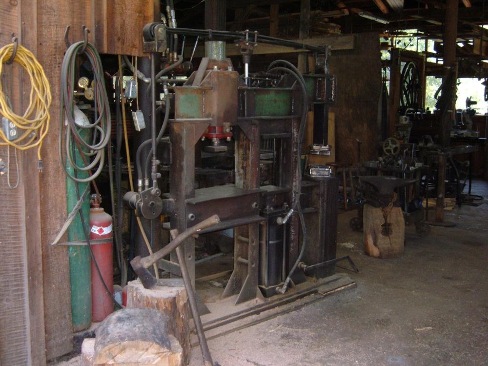

-
Hydraulic power hammer possibility?
poleframer replied to Ben Potter's topic in Power Hammers, Treadle Hammers, Olivers
250-300, if I rev the engine, but with 65 lb, 3/4" thick (at the center) leaf springs it's about to take off. I never run it as fast as it can go. If I do the top die will start hitting the head. But then I have the pin in the cam wheel at the furthest out hole for maximum whappage, if I moved the pin closer to the hydraulic motor shaft I get shorter stroke, and could go faster. I havnt done the test there was a thread about years ago, but it will easily take a hot 1" bar down to 1/2" or less in a few hard hits. I sort of play around with how I want it to hit, and how fast by elevating the spring pack, to have it hitting at the speed I like, if I want to hit harder I just go a little faster with the treadle, or go slower for lighter blows. I'd suppose at 100-120 bpm the head is going about 8 inches up and down, and I have about 16" between the dies if the top die was to the head. -
Hydraulic power hammer possibility?
poleframer replied to Ben Potter's topic in Power Hammers, Treadle Hammers, Olivers
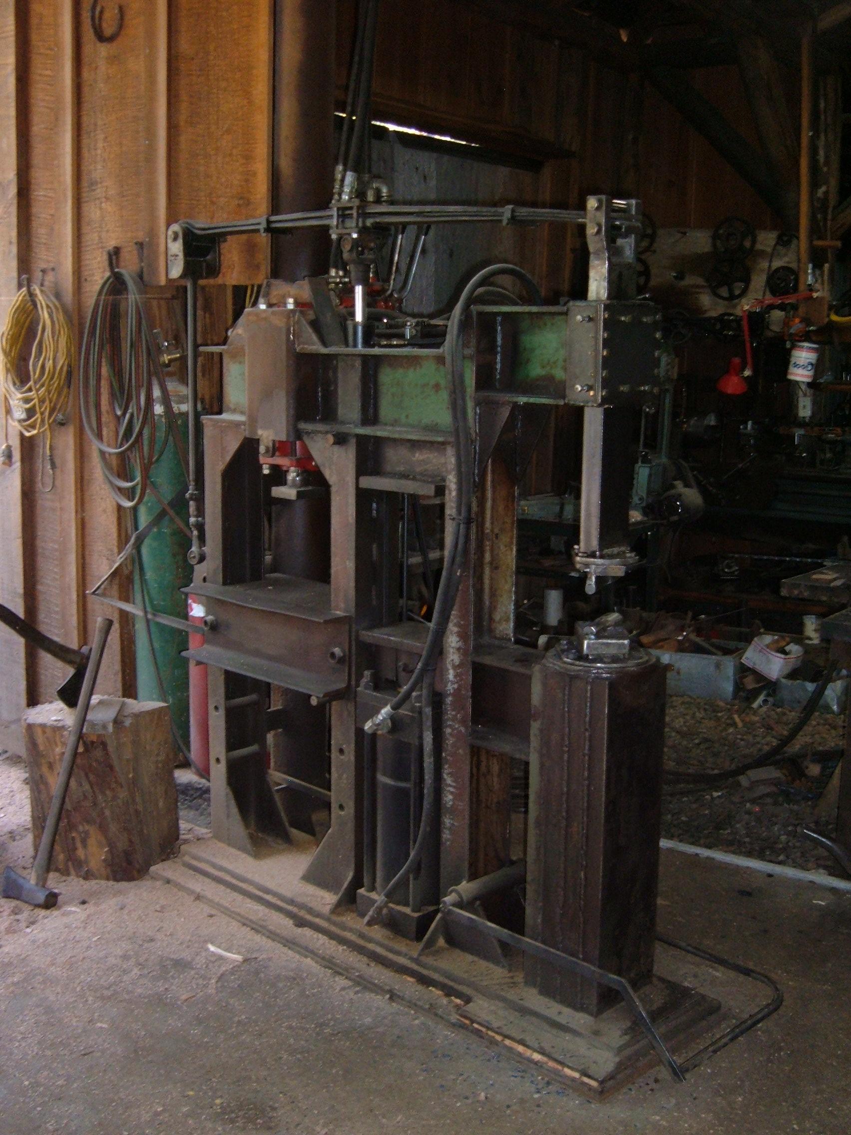
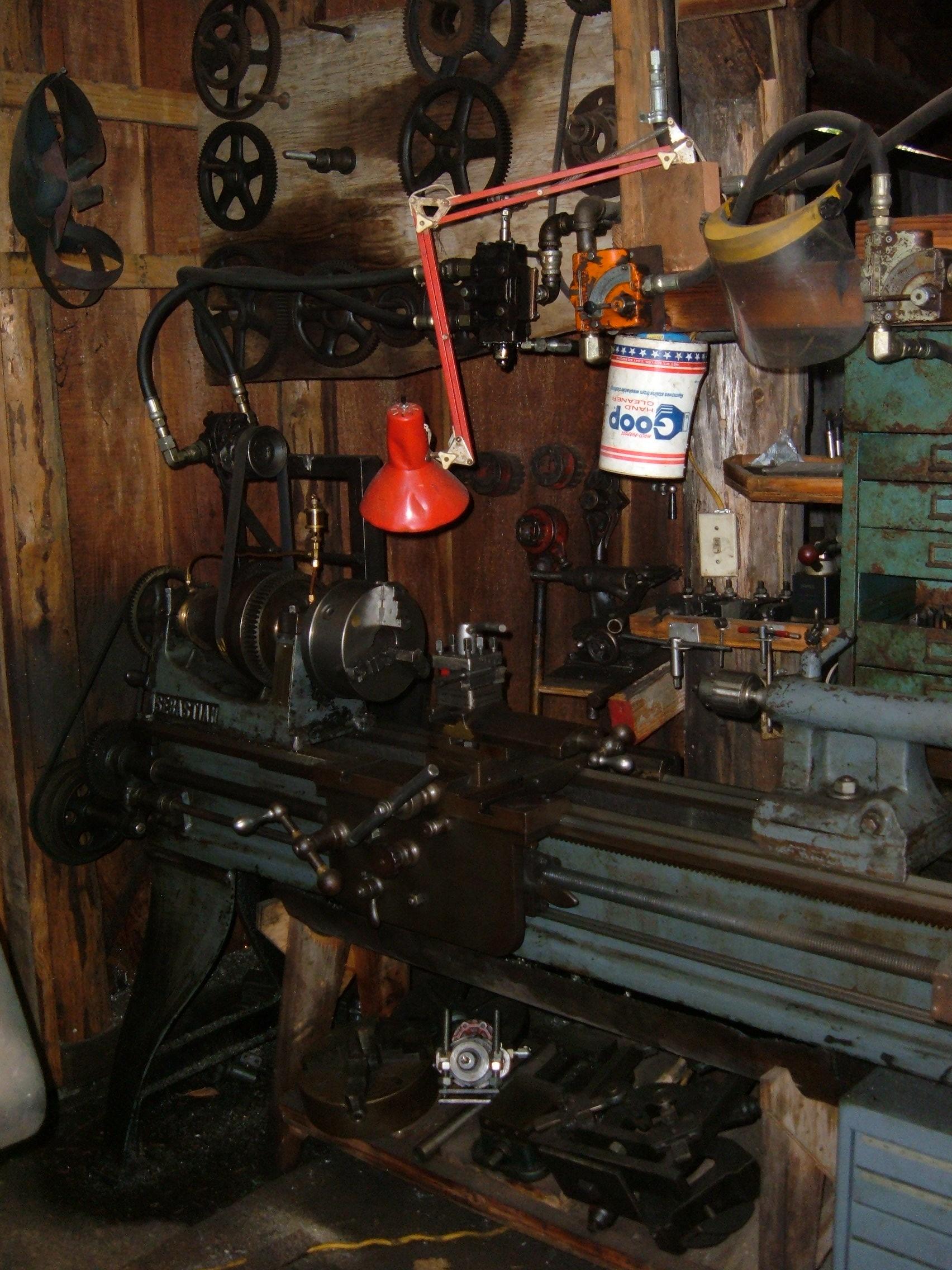
I have a hydraulic power hammer. No working camera atm tho. Might find an old pic or two somewhere. It is basically a "rusty" style hammer on steroids. Has about a 75-80 lb 2x4 solid steel bar with bolt on top dies for the head, and 2 dump truck springs. The "cam" plate that connects with a long drag link to the rear of the spring is mounted to a hydraulic motor. The motor is controlled by a flow control valve, which is activate by the foot pedal, giving varying speed control, I can even one hit quite well with a tap of the pedal. Now the center pivot of the leaf springs is mounted on a hydraulic cylinder that has a control valve next to the ram head for easy adjustment of striking height. I can go from slapping the dies to about 7-8 inches up. Oh, an since it is so long, about 6' overall (5' long leaf springs) I ha room to put a 7" bore cylinder for a push-up forging press, an a 5" bore top own press next to it, all under an in line with the leaf springs. That machine, my lathe, a big bandsaw (30" parks), a couple belt sanders and a iron twister are powered hydraulic with a 2 stage pump on a 15 hp diesel engine outside that I usually run just above idle for good speed, unless I feel spicy and crank it up :) I'll see if I can fin some stored pics if anyone is interested, I think my old photobucket is still there. -
Building and designing a shop, the best of the ideas
poleframer replied to Glenn's topic in Building, Designing a Shop
Give yourself as much elbow room around the shop as you can. If you have a clearing you want to put the shop in, and have the property to push it back, do so, having enough room for trucks to turn around, and guest parking is a thought as well. Trees are nice for shade, but a sufficient clear fire zone is a must. -
Not to my knowledge, I have a Parker 6" 3000psi rated tie rod cylinder in my forging press. It was a 20" stroke, too tall for my want of a bottom up press, so I turned down the tube and re-threaded the bolts to 14 inch. I could get the numbers off the tag if that helps in your search. I know you'll hate me for this, but my friend got 2 of them for 100 bucks each at the scrap yard, we built 2 presses around them, I cut them down (the 3.5" rods were fun to cut), I think the tie rods were 1 inch thick, one end threaded about 2 inches into the flat bottom block, so I put the threads I cut into that, and used the factory nuts on the top.
-
Brooks power hammer info needed
poleframer replied to basher's topic in Power Hammers, Treadle Hammers, Olivers
Might be a candidate for hydraulic power? Use a hydraulic motor with a flow valve to the treadle for the rotation, and a small cylinder to motion the fulcrum where you want it with a valve nearby. You could adjust the throw of the hammer on the fly. ...Oh, re-read your post, you are thinking a hydraulic motor already, cool. I dont think you'll need a brake, mine stops on a dime when I let off the treadle, the flow control valve I use isnt a motor spool (which are designed to let the motor coast to a stop), the motor stops almost instantly when the flow is cut to it. -
Did I read that right? You're handing out spouses and minor dependents?
-
I don't know if anyone here knew him, he was a talented smith who lived in Takilma Oregon, I knew him at a distance for many years, tho I did get called to chase down his horse a time or two when I lived in takilma. He was a blacksmith for Pirates of the Caribbean, he set up the blacksmith shop in the movie, and forged many of the knives used in it. He was also a tall ship sailor, and crewed on the Lady Washington. As well as a founding member of the Jefferson Baroque Orchestra, and many more praiseworthy accomplishments. I was looking at the Hay Budden anvil in my shop that came from him, I'm glad I'll be pounding hot iron on it for years to come. Prayers for his family, and bon voyage to a great blacksmith.
-
Little Giant clutch mandrel ?
poleframer replied to MLMartin's topic in Power Hammers, Treadle Hammers, Olivers
Another babbit pouring trck is to use oiled tissue paper, wrapped around the shaft to be poured around. Not TP, the best is the stuff that comes in new shoe boxes, it's a little tougher. Wrap around once with the tissue, oil it to keep it on the shaft, set it centered in the cups to be poured, dam the ends and pour carefully to avoid any voids. The shaft will tap out easily, and have the right clearance. I poured the babbets in my parks 30" bandsaw this way, and they turned out well. -
My first anvil build - looking for advice
poleframer replied to stromam's topic in Anvils, Swage Blocks, and Mandrels
Are you planning on just welding the seams on the outside? You might get a tight enough joint if you slightly convex grind the pieces to pull them tight together, but you might end up with deadening gaps between the pieces. Or you can through weld it. It will take a while, and a lot of welding rod, but here's what I did when I built up an anvil for a power hammer from large pieces that were stacked. I tacked a piece of 1/4" square down the middle of one and then laid it on its side, lined it up with shims to the other piece and ran a bead in the gap, flipped it over and ran a bead on the other side. It took hours of welding, flipping it over and checking for true on each pass (just run additional beads on one side if you need to pull that side in), and using a long rod to clean the slag on each pass. Eventually you have a full pen weld. I used 5/32 7018 rod, and not too much problem with distortion when done. -
high speed cutlers power hammer project.
poleframer replied to basher's topic in Power Hammers, Treadle Hammers, Olivers
Might be of interest that the hammer runs at around 500 psi or less. My system is more designed for higher flow, less psi. I run a 30" bandsaw (old parks resaw) off it as well with a hydraulic motor, and it hits maybe 800 psi pushing 10" of oak through, cuts smaller wood at under 500psi. My lathe or belt sander rarely go past 800 psi either and I have no complaint about the torque on those. I do slow down the bandsaw gradual to shut down, with a flow valve, it has big cast wheels to slow down, but rarely have had anything chucked up in the lathe not to just stop it rapidly turning the flow valve to off. I have been living with hydro-electric power for 20 years (25 gpm at 140 psi), line hammer is definitely an issue I know about with that. In the context of heavy duty hydraulic motors, and oversizing for flow, the problem is non-existant. All my lines are min 1/2" hose, and oversize steel tube for the shop plumbing. Idk how well a power pack will do, considering that most were made for presses, and are designed for higher pressure and lower flow. I'm running around 10 gpm, and use a 6 cu in motor for the hammer, a 2.5 cu in on the bandsaw. I think as opposed to an electric motor, in this context the motor wear is less in a hydraulic motorin that that the hydraulic motor gears are in a cushion of oil, you're electric motor bearings, and motot parts would be getting a lot more abuse in sudden start-stop use. Just my .02, could be totally wrong. Nothing fancy for the connections, just plumb the CF port on the control valve to the hammer motor in, and out to return. if you want to run it the other way just reverse ports on the motor. -
high speed cutlers power hammer project.
poleframer replied to basher's topic in Power Hammers, Treadle Hammers, Olivers
Maybe before commiting yourself to either, set up both, attached to the bearing block and bolted down, and see which method gives the control you like the best. I tend to think a hydraulic motor will start and stop on a dime better than an electric motor, I can go from full speed to stopping the head exactly where I want by taking my foot off the treadle and shutting the valve off there. Part of the trick is to have the flow control valve as close to the motor as possible, I wouldnt put the valve at the treadle with long hoses, I'd put it close to the motor with treadle linkage to the valve lever. -
high speed cutlers power hammer project.
poleframer replied to basher's topic in Power Hammers, Treadle Hammers, Olivers
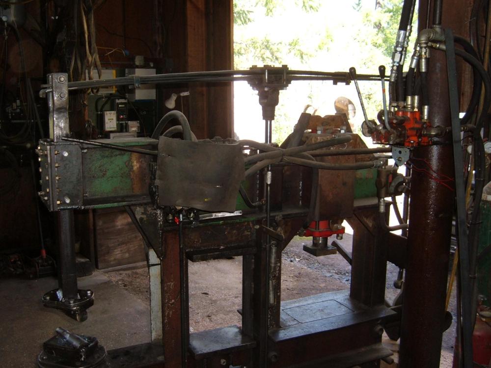
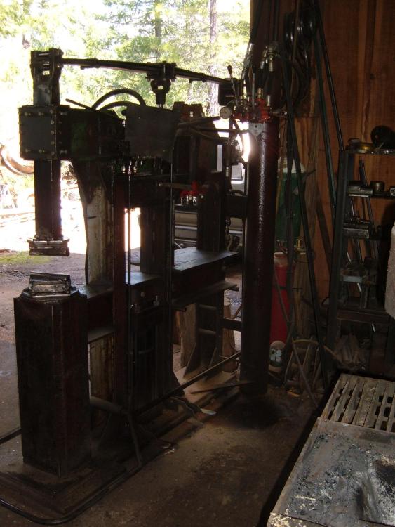
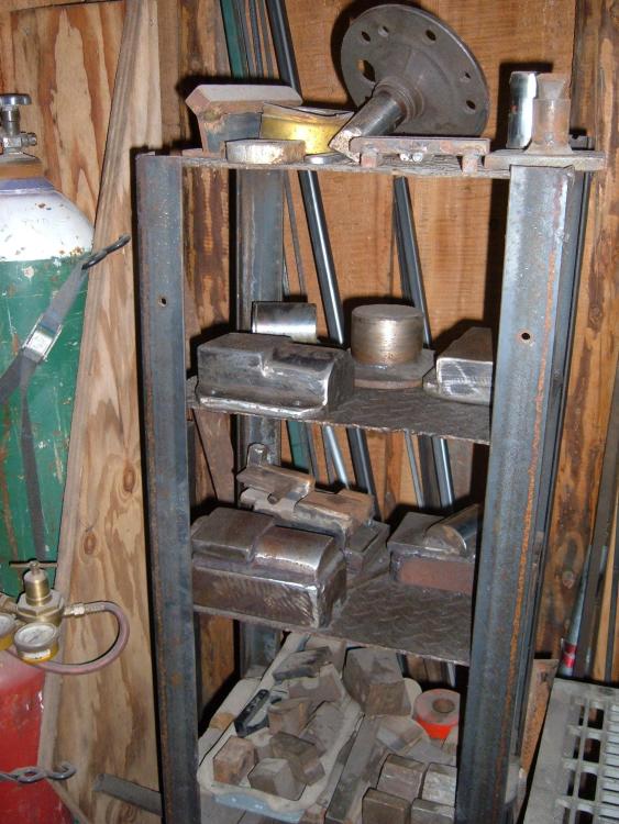
When you say inverter controlled hammer, do you mean treadle direct to a VFD controller? My buddy and I built two of these press/hammer units, I'm off the grid here and use a diesel for my power source, I tend to run it at half throttle, sometimes raising or lowering the RPM/flow rate for what I'm doing (will be doing, spent most of last winter working on this project). He set up on a 15hp 3-phase, and those presses really go fast. I should check the hammer speed with a laser tach I have, it seems pretty fast too, faster than I'm comfortable with. A VFD control on the motor would give another level of control for sure. But then for you a VFD controlled motor running a hydraulic pump, and hydraulic from there may be getting over complicated for what you're doing. Do you have a video of the inverter controlled hammer? Here's a couple shots of the sister hammer to mine. -
high speed cutlers power hammer project.
poleframer replied to basher's topic in Power Hammers, Treadle Hammers, Olivers
Idk if you remember the clip of my old hydraulic motor hammer.I havnt taken any vids of the new one. I've thought about a tire hammer arrangement, with the same method. Say you lose the tire and motor, have the concentric on a hydraulic motor, treadle to the flow control valve. To size the motor, just figure your system gpm and size a motor for the rpm you want to hit at full out. The new hammer has that control, one hits nice and hard, with the small hyd cyl under the spring pivot changes the hammer strike, I can adjust it up and down, withing a 1/4" of where I want, with the spring fwappage accounted for, light taps, or roundhouse swings. The presses are what made the footprint of a 6 foot long machine work for me. old hammer vid, before I got the dies done right http://s719.photobucket.com/albums/ww194/LogDork/?action=view¤t=hammering1.mp4 new hammer PS, in the video, I was just demoing on cold stock, It did a good job with improved upper die and hot iron. It was abbout a 25 lb head, the new hammer head weighs about 80 with the die. Idk if the 65 lb spring pack adds as part of the tup. -
Hey Bruce, looking good. Been on logwork a lot, but toying with a few ideas still. The gearcase here is out of a small john deere tractor, powered with a hydraulic motor. Still prototype, will be needing a heftier I beam to attach the powerhead to. Took out the spider gears and made a sleevable chuck that fits snug in the diff case. I will be building a cover over it before I get much further with it. John Deere Twister