
Stormcrow
-
Posts
1,095 -
Joined
-
Last visited
Content Type
Profiles
Forums
Articles
Gallery
Downloads
Events
Everything posted by Stormcrow
-
My buddy who lives halfway across Texas stayed with me about a week after Christmas and helped me do some work on getting my home-brewed power hammer finalized in order to make some candle holders he had commissioned from me to give as Christmas presents. Here's what we came up with: A set forged from pipe for his soon-to-be-fiance's brother, sister-in-law, and one-year-old: Another pipe set for my buddy and his girlfriend: And a pair for the girlfriend's cousin and wife, forged from approximately 2" round: I love this texture and will be using it on more projects. To me, it makes the candle holders looks like the Dark Tower of Barad-dur. And being a crreative fellow himself, my buddy did not sit still while I was working. He made these ladles with riveted copper handles for his girlfriend:
-
New Style Kinyon Project / Drawing
Stormcrow replied to ajclay's topic in Power Hammers, Treadle Hammers, Olivers
This design is essentially a guided helve hammer that replaces the eccentric and clutch with an air cylinder, right? I know I've seen pictures of a number of these kinds of hammers with the eccentric linkage positioned in the middle of the helve. Take a look through the different threads about helve hammers on here and see how their eccentric linkages are set up and it should help solidify how you want to position your air cylinder. To me it looks like it would be pretty much straight up and down and maybe replace the spring pivot at the top of the ram with a roller system a la Rusty. Then just a simple pivot at the back would do. Also, you mentioned that the air cylinder pushes harder than it pulls. Wouldn't it make sense to turn the air cylinder the opposite way you have it drawn? That way it will be pulling the ram down onto the work with maximum force and then quickly raising it back up. Am I looking at this right? The more I think about this basic design, the more I like it. I have been wondering the past week or so in an idle sort of way how one could set up a junkyard guided helve hammer with an air cylinder to give better control. This looks like a fairly elegant solution if you can get the positioning worked out. -
New Style Kinyon Project / Drawing
Stormcrow replied to ajclay's topic in Power Hammers, Treadle Hammers, Olivers
Woops, somehow missed that there was a whole other page of comments. The video makes it clearer how it would work. I'd really like to see video of the actual hammer running when built. -
New Style Kinyon Project / Drawing
Stormcrow replied to ajclay's topic in Power Hammers, Treadle Hammers, Olivers
Interesting design. I'm no expert, but I am tuning my own home-brewed hammer right now (modified Appalachian style) and I've gotten to work on a couple of different air hammers and a Little Giant. With my Appalachian style hammer, I found that when the springs were too stiff (three almost equal length truck springs shackled together at the ends) they acted more like a solid beam than a spring and wouldn't hit particularly hard. When I replaced the helper springs with shorter ones that were unshackled, the main leaf had a nice whip and hit hard, but would be too whippy when running at high speed. The S-curve developed could not whip out fast enough to keep up with the rotation of the eccentric and the top die actually would not contact the hot steel at all when running flat out. Since I put back the original helper springs cut to 1/3 the main leaf's length and shackled them at their ends, it's hitting right like it needs to. So spring whip is very important. The way the cylinder is set up where it's attaching near the end of the spring isn't going to let it whip much. What if you set the cylinder vertical and built rollers on the top of the ram to let the end of the spring roll in and out the way the Rusty hammers do? Seems like you'd be getting a lot more use out of your spring. -
I finished up and delivered the copper baptismal font recently. Here's how it ended up after final shaping: It's approximately 29 3/4" across the inside of the rim. After cleaning up with muriatic acid: And after going over it with a ScotchBrite ball chucked up in a drill: Although shiny, the basin is highly textured, with ripples left from the raising process and hammer marks from sinking it. The church wanted this rather than a smooth, perfect finish. Personally, I really like the textured finish, particularly the ripples, which mirror the ripples of the water. A steel stand was fabricated for it at another shop, then plated with a bronze patina at a third. Finally, after many months, it was delivered and installed at the church. If you look to the left of the large doors at the back, you can barely see it in this picture: In addition to being used as a baptismal font, the basin will stand next to the door and hold holy water. And here I am, looking dirty but pleased to have it in place. I have a lot more pictures and footage of the process of making it that will be put together into videos and uploaded to my Youtube channel at some point.
-
Test run of my new power hammer
Stormcrow replied to Stormcrow's topic in Power Hammers, Treadle Hammers, Olivers
Having gotten my die holding system worked out (and seems to be working great so far!) and finally getting down to some real hammer time, I found that I have a few more issues to tweak, which I will try to get done before the New Year. 1. Add a greasing system to the ram guide. A couple of zerks, some channels milled in the plastic, and I'm good on that. 2. Re-stiffen the springs somewhat. I've discovered that the spring is now *too* whippy. It forms an S shape under power, and when going full tilt, the eccentric is rotating faster than the S can unwind itself and whip the ram down. This means that when trying to hit hardest and fastest, the ram often isn't hitting at all and you have to ride the clutch, which wears the tire. I'll put the original helper springs back on after I shorten them. 3. The wheel keeps falling off! It's held to the shaft with a key and a set screw. I need to put some Loktite on the setscrew and that should solve the problem. 4. I'll ascertain this for sure once I start playing with hand-held tooling a bit, but I'm thinking I may want to shorten my linkage up a bit. The adventure continues! Thank goodness I've been able to understand what is going wrong at every point and been able to fix it. One of the big reasons I went with this design: simplicity! This is only the third level of complexity in a power hammer. 'Course, if I had a big air compressor, an air hammer probably would have been better. Some day, when I'm making more money! -
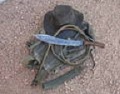
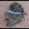
Thanks, guys! John - Yep, it's me. Chose "Stormcrow" as a fairly generic, disposable pseudonym, and here, almost a decade and a half later, I'm still using it. Like most things in my life, that arrangement that was intended to be temporary has become permanent. Ironsmith - They are nice and comfortable. The forge finished knife has a bit bigger handle and fits me better, while the other ne is a bit smaller and was more comfortable in the hands of a friend (not the one these were made for) with smaller hands. I used a new trick I figured out to shape them. I epoxied the handles onto the tangs as a block, no shaping done. After letting them sit clamped overnight, I used my angle grinder with an aggressive stiff sandpaper disk to rough out the handle shape and take most of the excess wood off. Then I finished up with my belt grinder and smoothing by hand. Those disks are a lot faster and a heck of a lot cheaper than grinding belts.
-
This is a pair of knives with some interesting history. They were commissioned by an old friend of mine from public school. One is for himself and the other for his father-in-law. He wanted one to be a bit longer and one to be forge finished and the other satin finished. The steel is leaf spring from his first pickup, and the wood for the handles is pecan because his father-in-law has worked in the pecan business for years. He changed his mind about which should have what finish after I had already forged them, so I had to leave a few spots of forge texture or grind too much steel away on the shorter one. I also re-forged the long one to get the blade down thinner, where I typically have it for a forge finished blade. This altered the shape a bit, but I liked it and went with it. I haven't done too many trailing tip knives, but think I may do some more now. I had never used pecan wood as a handle material before and was surprised at how much figure the wood had. It was bit light, but darkened up when I oiled the handles. I like it! Something I read years ago: "Real Texans know that it's pronounced puh-KAHN. A PEE-can is something that goes under the bed and empties out the winder."
-
I've been working hard this past week building a quick-change die-holding setup for my new home-brewed Appalachian style hammer. It has been briefly tested as of tonight, and seems to be highly satisfactory. I've never seen anyone else running this setup, but I'm sure it's already been done. Most hammers either have a dovetail system or use bolt-on dies. Since this is a home-brewed hammer and I want to be able to make my own dies since I am mucho el broke-o, and since I have no machining training, dovetails were right out for me. When it was time to build the hammer, I had this system and bolt-on dies as possibilities, and we went with the bolt-on dies initially. A lot of these Rusty-style hammers are built lighter, and it's easier to hang the base plates of the dies off the edge of the ram and anvil, making drilling mounting holes fairly simple. We drilled and tapped the holes directly into the ram and anvil of this hammer, and it turned out that none of the holes were square to each other. I built my first set of dies that let me test the hammer and see what changes needed to be made, then tried to make a template that would let me drill the appropriate hole patterns. The template matched the holes in the test die's base plate, which would bolt to the anvil, but did not match the holes in the anvil. I found this most confusing and off-putting and realized just how much time I would spend in frustration trying to get bolt holes to match every time I made a new set of dies if I continued this route. So I changed course and went with my other idea, this quick-change system. I've spent the last couple of days (among other things) building a set of combination dies out of railroad track that would a.) serve me well for many years, b.) allow me to test my new die-holding system before welding base plates onto my espensive 4140 fancy shmancy flat dies that will be my main dies and tooling platform, and c.) do a paying gig that needs done in time to ship for Christmas. A student of mine was finishing up a project tonight and had time while it was tempering in the toaster oven, so we decided to test the new dies/die-holding setup and make her a pair of tongs. The dies have not yet had their final trueing up and the sharp edges rounded, and I don't yet have much time working with the hammer and am still getting a feel for the level of control, so the tong halves came out rough but will be serviceable. A view from the back side of the die. The narrow section was freehand cut with an oxyacetylene torch, then given a quick cleanup with an angle grinder. Final trueing and edge rounding still to come. A view from the front, showing how the system actually works. The die is welded to a base plate of a standard dimension. In this case, I came across a whole bunch of cutoff drops at Ashley Salvage here in San Antonio that were 6" x 8" x 3/8". Since my ram is 6" x 5" at the bottom, this was perfect. I bought more than I thought I would ever need just to be sure I don't run out. The "keeper" slides that actually hold the dies in place are machined from 1" square cold rolled steel. This took some doing, as I have had no training in machining, and didn't have an adequate milling vise. I actually had to work on other things for a couple of days while I waited on one I bought from eBay was delivered because I had no other way of precisely holding the bar like I needed. The die base plate slides under the keepers and butts up against the stop at the back, once again made from 1" square. Then the swing arm is shut, the bolt tightened down, and the whole thing fits nice and snug and didn't move during the test run. This picture is with the die pulled partway out of the keepers. In spite of the blurry picture, you can see three dots on the inside of the swingarm. These are little dollops of weld bead. If the base plate is a bit too short or uneven, these dots contacting the edge will help even everything out and make sure that the die stays snugly in place while being wailed on. The fit is a bit too snug. When welding on the baseplate, it invariable warps upwards. However, these dies were plug welded as well as welded along the sides, and this kept it from warping as much as they might have otherwise. I thinned down the edges quickly and dirtily with an angle grinder to get them to fit in for tonight's test run, but a quick pass or two on the milling machine in the fulure will take care of things. How well did this work? Being able to quickly change the dies is only a secondary consideration with this. However, it is an important one. I was able to take the top die out and turn it 180 degrees between heats so I could forge the offsets in the tong halves. The dies didn't even think about moving. I'm able to put the dies in either direction and top or bottom, somehting I would not have been able to do with the out-of-square bolt-down system. It is a bit bulky, but taken altogether, not so much as a dovetail sow block. I added 8 pounds 4 ounces to the ram, not including the weld beads, so I essentially have an 88 pound ram now. Like I said, I don't recall ever seeing anyone use a similar system. I think I figured this one out pretty much myself, and I'm kind of stupidly pleased that I was able to do so, to borrow a phrase from another smith. Hopefully this will help someone out. Oh, and the tong halves: I'm kind of embarassed to admit that this is only my second pair of tongs I've worked on. Given that, the fact that the hammer tooling was not completely optimized, and that I was still getting used to the feel of the hammer's control, I think they're ok. There is still more work to be done before they're finished, including finishing drawing the reins out and roudnding the sharp corners, but we ran out of propane it it was the end of class time anyways. We'll pick it up again next year and finish them out. Now to make more dies and auxiliary tooling. :)
-
Power hammer parts.....
Stormcrow replied to FieryFurnace's topic in Power Hammers, Treadle Hammers, Olivers
FieryFurnace - Check a few threads down and you can see the Appalachian-style hammer that my cousin and I built for me, which utilizes a tire clutch. One of several reasons I went with this design is because it is so very simple, only two steps higher in complexity than the absolute simplest power hammer design. I can understand it, and if something doesn't work right, I can fix it. Mine is built on a bit larger scale than the average for this design, but overall works pretty well. I think it might be a bit heavy for the tire clutch design as I am losing some rubber off my spare tire, but I'm thinking of adding a layer of round hay baler rubber strap to the outside of the wheel or just swapping to a full-size tire. I'm in the final phases of major tweaking, then will shoot a new video showing what alterations I've made and showing it in operation. How big of a ram are you wanting to operate? Mine is an 80 pound ram, not counting the weight of the dies. I'm about to add a bit more weight as I change how I hold the dies on. Overall weight of the ram is in excess of 100 pounds with the dies. Most folks run these with 25-65 pound rams, and a lot of them use a 1 horse motor. I'm running a 3 horse motor (because I got it for free), and have no problem with it when I start pounding. I've seen video of hammers of this style with slightly heavier rams than mine, but nothing significantly larger. 100 pounds seems to be about as big as folks build this design. I don't know that that is the limit of the design, but 100 pounds can flatten steel in a hurry, and should cover the needs of most smiths. To sum up my rambling thoughts, I think that as long as you are building a medium to small size hammer (what most folks build), you will do just dandily with an Appalachian-style hammer using a tire clutch. If you want to draw from my experience a bit more before you start your own, give me a few days. I have a Christmas gift order that I waiting on my to get my die system finished and a pair of dies built. You can see how it works now that I've made my changes. -
Test run of my new power hammer
Stormcrow replied to Stormcrow's topic in Power Hammers, Treadle Hammers, Olivers
Thanks, Sweany! The base is 1.5" thick, 18" wide, and 6' long, and it's anchored into the cement with four good-sized bolts. When we test-ran it sitting up on wooden blocks, it didn't threaten to tip over or anything. Arftist - Finally measured those springs. They are 3" wide and .5" thick. -
Test run of my new power hammer
Stormcrow replied to Stormcrow's topic in Power Hammers, Treadle Hammers, Olivers
Update - I got my springs sorted out. I took off the top and bottom helper springs, which were about as long as the main spring and shackled to it at the ends, and replaced them with some of the medium-short leaves out of the stack, which still had their arch. These were approximately 1/3 the length of the main leaf. What a difference! We had essentially converted the springs into a solid beam. With the main leaf free to flex and do its thing, the hammer hits nice and hard. It contacts the helper springs right at about the extreme of its flex, not putting undue stress on the main leaf (I believe). Turns 1" square into very thin flat with alacrity and ease. In fact, I may move the pivot point of the eccentric back down a notch or two to shorten the stroke and take the power down a bit for general forging. I'll have to play with it more and see. I'm working on changing from bolted-on dies to a quick-change system. After I'm done with that, I'll shoot a new video documenting the changes and showing how hard the hammer hits. I do have to say, I think that this is probably about as much weight on which a person would want to use a tire clutch setup (it has an 80 pound ram, plus the weight of the die, coming in over 100 pounds). It's eating rubber a bit. I'm thinking about putting a layer of sacrificial rubber, perhaps inner tube or round hay baler belt, around the tire. Would a slack belt clutch with a flat belt be the next step up on a machine like this? -
Question on helve hammer build
Stormcrow replied to Bad Creek Blacksmith's topic in Power Hammers, Treadle Hammers, Olivers
Grant, whenever anyone mentions brainstorming, I get a mental image of brains falling from clouds to splat on the ground. You're right, I'm taking away much of the advantage of using a block in the first place. It just seems to me like the most complex part of the OJH design is the piston portion of the linkage. Especially if one doesn't know about welding aluminum. A man sees projects through the lens of his own limitations, much of the time. You're not running the engine with an oil pan on it; what about turning it upside down so the linkage isn't trying to clear the walls of the cylinder? No need to make any kind of wobble joint in your linkage then, right? Not as good of a surface to put your anvil on, but you've already said it wasn't enough mass anyways. Is using the crank to provide eccentricity the easiest way in this case? The eccentric setup we did on my hammer was pretty simple, although we did have to use a couple of bearings and pillow blocks for it. Pretty much the same as the one in the DePew thread, but with a tire clutch. Personally, I think the OJH was pretty darn cool and wish I had had enough mechanical understanding to build something along those lines when I started out. -
Question on helve hammer build
Stormcrow replied to Bad Creek Blacksmith's topic in Power Hammers, Treadle Hammers, Olivers
Grant, after guiding the building of my own modified Appalachian and seeing the DePew design, looking back on this, it strikes me that using the piston of the motor seems to add a lot of complexity without too much benefit. What would you think of using the shortened crankshaft and eliminating the block? Maybe orienting it 90 degrees to the direction you had it so you don't have to deal with sideways forces on the linkage from the crank up to the helve? Bad Creek - I really like the homebrewed DePew-style helve hammer posted by coolhand on the second page of this thread: This is about one step up in complexity from the simplest power hammer design I can think of, with the Appalachian "Rusty" hammer being one step higher than that. Hope this helps. -
Test run of my new power hammer
Stormcrow replied to Stormcrow's topic in Power Hammers, Treadle Hammers, Olivers
Arftist - I'll try to get approximate measurements today. As for the blows per minute, not sure, but you can see how fast it was hitting in the first video. So I've increased the new hammer's power of its blows by increasing the length of the stroke, but my springs are now preventing me from getting as much power as it could. There are three fairly heavy truck (not pickup) springs in the helve, all about the same length, shackled together at the ends. Thinking about it, not a great way to get the spring to whip. I've actually had to crank the dies down to where there's no daylight between the die and the steel being worked in order to get it to hit, which I know isn't a good thing. So I need to alter my springs. Here's what I'm thinking: If I shorten the top spring to about 1/3 the length of the main leaf (in the center) and arch the end a bit to reduce stress per the suggestion of another smith who made a nice one of these, can I leave the bottom spring long on the ram end of the pivot as long as it's not shackled to the main leaf? Seems to me like that wouldn't affect the hit, but could help support the main leaf as the ram is being lifted. Make sense? For that matter, what about leaving the top leaf long on then back side of the pivot to help brace the main leaf on the down-stroke? Seems to me that it would preserve the whip on the fore-end and reduce it on the hind end, maybe delivering more force in the blow. Is that a good thing? Am I thinking about this right? -
Test run of my new power hammer
Stormcrow replied to Stormcrow's topic in Power Hammers, Treadle Hammers, Olivers
Fcion - Thanks to your clarification on the adjustment holes, I was able to realize part of why my hammer wasn't hitting as hard as it needed to: it was short-stroking. I moved the pin to the furthermost hole (after having to do some cutting and welding to deal with clearance issues) and now it hits a lot harder. Thanks! Update: I've had to do some tweaking now that it's actually wired and able to move. I extended my contact wheel so that it actually covers the whole length of the tire, I had to shave a bit off the eccentric/flywheel to clear the motor housing when going full tilt, and most importantly, I moved the pivot bolt for the eccentric to its furthest-out hole, which lengthened the stroke. It hits a lot harder now. I still think I can get more power out of the machine. I have three leaf springs stacked. I think they are keeping the helve from whipping appropriately. I'm going to study the situation some more and then probably remove one or both of the secondary springs. And then I'll move on to changing my die holding setup and maybe brace the anvil a bit more. Ah, the joys of using home-brewed machinery! -
Test run of my new power hammer
Stormcrow replied to Stormcrow's topic in Power Hammers, Treadle Hammers, Olivers
Yeah, I think you're right. The adjustment holes are actually something my cousin came up with, and I think I'm a bit confused on it. Your explanation makes me see it better now. Thanks! I'd say if anything about this hammer is innovative, it'd be that. -
Test run of my new power hammer
Stormcrow replied to Stormcrow's topic in Power Hammers, Treadle Hammers, Olivers
A few more details of the mechanism. -
Test run of my new power hammer
Stormcrow replied to Stormcrow's topic in Power Hammers, Treadle Hammers, Olivers
Thanks, guys! Don't worry, Bob, he got paid. And this is the last big piece of equipment I need for a long time. I'll get more pics and/or videos up before long. -
I finally got my new power hammer wired! This is its first run. It was built by the same cousin who built the hydraulic forging press. It's a modified Appalachian "Rusty" helve hammer utilitizing a spare tire clutch. Very little new material went into making it. It has an 80 pound ram and is running dies made from railroad track caps. More dies and a different die holding system in the future. The test piece of steel is about 5/8" automobile coil spring. The Hausmann Millworks mentioned in the video is the creative community where my shop is located, just north of downtown San Antonio, Texas.
-
Hey, guys, I keep seeing Clifton Ralph's videos being recommended for learning some of the capabilities of power hammers. I'm having a devil of a time locating where you can buy these videos, though. Anyone know where they can be found? Any other good videos out there on the use of power hammers and hydraulic forging presses?
-
My new Rusty style Power Hammer
Stormcrow replied to Mark Wargo New2bs's topic in Power Hammers, Treadle Hammers, Olivers
So what's the verdict on your hammer? I have a very similar but heavier one in the works. It doing the job? :) -
Tire clutch ratio question
Stormcrow replied to Stormcrow's topic in Power Hammers, Treadle Hammers, Olivers
That was very helpful. Thank y'all! -
The cousin who put together the forging press for me is now working on a power hammer for me. It's a modified Appalachian (Rusty) hammer but using a tire clutch. The ram is 75-100 lbs, with a 3 hp 3 phase motor running it. Our tire for the clutch is a 19.5" diameter. What should the diameter of the contact wheel on the motor be for an appropriate number of beats per minute for this size hammer? Much appreciated.
-
As of now, it sits almost like it is at the end of the video. I did a bit of test hammering with the help of the guy who was filming, him holding and rotating while I hammered. It made a world of difference. Another fellow is supposed to help me with it when he can. I'll be raising for the next step, using the other hammer you can see in the last shot. Beth - It'll end up being around 6.5-7" deep and 2.5' across. Nice commission, but I way underbid it. My fault. Live and learn. Ah well, it's for a church.