
Adair
Members
-
Joined
-
Last visited
Everything posted by Adair
-
Every once in a while I think on this hammer and what became of it. Are you still out there, Basher? is this hammer still waiting for its purpose?
-
Latticino, Clayworks, Thanks for the input, recommendations, and especially the link to the other thread. Maybe we'll experiment with that burner in the future, I am intrigued now. For now I've offered to help my friend build a side arm burner for his forge. We'll spend less time fiddling and experimenting since I've made a few for my shop. Cheers, Adair
-
Thanks for your thorough moderating, Steve! -Adair
-
Mikey, Thanks for your evaluation. Were it my forge, I would just build a burner, but my experience is limited. I thought since this was a manufactured item that there may be something more to it. Curious why a moderator changed my post title from Assess to Access. I have plenty of access to the burner, it's an assessment that I'm interested in.
-
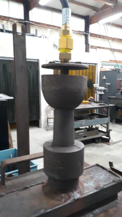
Frosty, Thank you for your quick reply. While I did not do it myself, I was assured that the jet was cleaned before trial. The geometry of this burner strikes me. The venturi burners I've built and most all that I've seen are much longer than this. -Adair
-
Hello all, A friend is trying to set up a workstation for his shop program. He was given this forge and a small forge chamber lined with refractory brick. He asked me for help getting this burner assembly set up. I've built a few naturally aspirated burners, but I don't know where to start with this thing. The orifice is machined integrally with the threaded brass insert at the supply end of the burner, so there is currently no adjustment of that component. Currently, when set up with a regulator at 20 psi there is a large amount of unburned fuel (blue flame). I intend to add a variable pressure regulator. It has an 1/8" gas line and ball valve. The only other variable that I am accustomed to would be a secondary air supply where the burner enters the forge chamber. Does anyone recognize this burner? If I can identify it then perhaps I can take some of the experimentation out of setting it up.
-
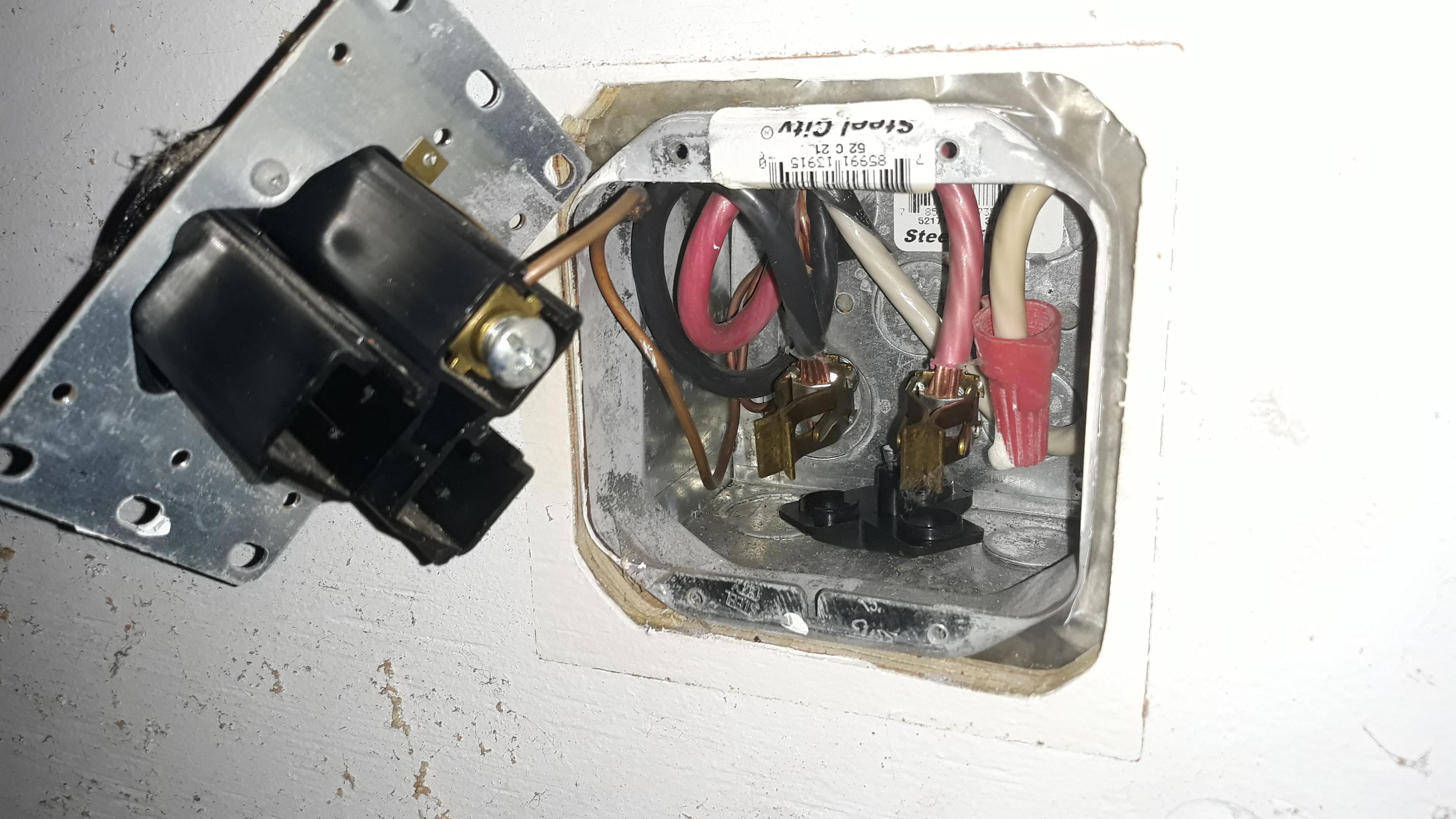
The panel was fine, all the other 50 amp outlets were fine. I took the outlet apart and found that the receptacle contacts had been pushed out the back end. The receptacle came out and the contacts were hanging on their supply wires. One lead had an arc on it so I'm very pleased to discover this. Thanks for your input. I plugged the hammer into another outlet and it fired right up. What a great little hammer! -A.

-
Thanks gang, I'll read up on how to run my my multimeter, start at the panel, then the outlet. -Adair
-
Hi there, Yes the motor was wired to the VFD, the hammer was running in its previous location as wired. I just moved the hammer to my shop, plugged it in and this happened. I've flipped the breaker and still no power to the outlet so as you stated, I guess there is something amiss between panel and outlet, though everything was fine before I plugged this VFD in. -A.
-
Hey all, I've never had a VFD in my shop, and I've never operated a VFD anywhere before. Yesterday I was setting up a used Striker 88 complete with Delta VFD controlling a 3phase, 5 hp motor. The power load matched what I had available in my shop, 240 50 amps. I plugged in the hammer and the VFD powered up momentarily then shut off. It it did not trip the breaker and now there is no power to the outlet. The outlet was installed by a commercial electrician and I have been running my other power hammer and welder regularly from the same supply. I'd like to know if there is something I overlooked in operating a VFD before I call an electrician. I have the manual for the device, but quite honestly I cannot decipher the contents. -Adair
-
One option I've used before that hasn't yet been mentioned is a mortise and tenon joint. I forged a new handle with an integral knob on one end and a round tenon on the other. The tenon need only be very slight. I forged a ball of matching size and drilled a hole to match the tenon and followed with a large countersink. I set the tenon with a torch heat, handle held in another vise. Some file work on the end and the tenon head disappeared. -A.
-
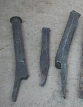
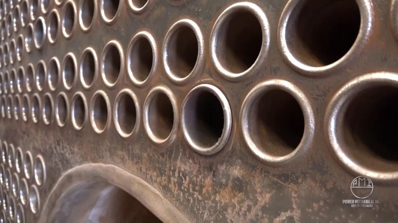
Affirmative. I've always thought it was curious how names can morph like that. I live in a town named Anacortes, it was named after "Annie Curtis". Thomas Powers I may be that "steamer" guy. I've been around live steam most of my life operating antique stationary and traction machinery. I've observed fire tube boilers being re-tubed and I've cut my fare share of tubes out of flue sheets. I've been reading about beading the edge by hand. The traditional tool, the "crow's foot" or "boilermaker's thumb" (see attached image of the two tools on the outside of the frame) is what one might expect and no different than the forms used today on pneumatic tools. the tube is upset as much as it is beaded over. A lot of force in small area is preferable to spreading that force over the whole circumference of the end of the tube, particularly when you consider that this is done cold.
-
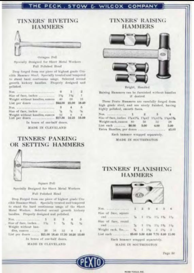
If you google "Pexto Raising Hammer" you will get many image hits for hammers in this style. They are coveted by the metalshaping crowd (the custom sheet metal forming community) and were marketed in catalogs as "Tinners Raising Hammers" (see imag below). Pexto is a common make but there are others who made nearly identical hammers. I've seen them in many sizes up to five pounds. Modern metalsmiths might say that the term raising in the context of this hammers' purpose is a misnomer, but that is another discussion. Thomas Powers: I'm curious how this form of hammer would serve seating boiler tubes. That work is usually done with a tube expander and what are called "crow's foot" flaring and beading set tools (hammer-struck or pneumatic).

-
Pnut, that is a great point. I suppose a lot of friction on the surfaces would really shorten the lifespan. Thomas, this hammer likely predates Yoder, Pettingell and Quickwork sheetmetal hammers but it is the same configuration. It won't be 900 bpm like a modern sheetmetal hammer, but it will be faster than a blacksmith's powerhammer. They were available in a few sizes, the one I'd like to build is the largest they made. I was trying to buy one for many years, but ultimately I lost out. My only option now is to build one.
-
Thanks for your input, Frosty. I'm willing to give it a try. I have to sort out the pulley sizes. This hammer is intended to run much faster than a forging hammer so I'm optimistic I can get smaller diameter wheels to work. -A.
-
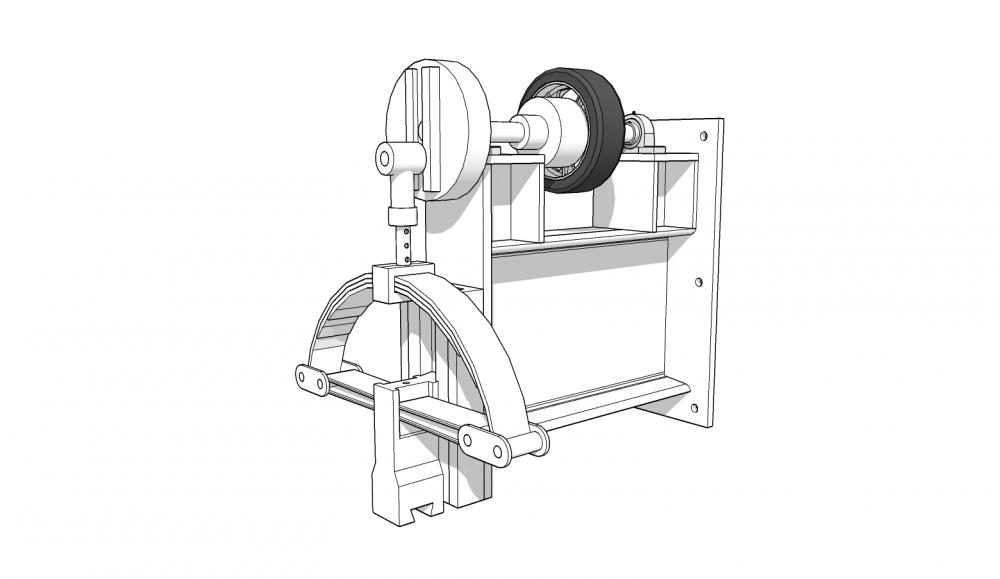
Hello all, I've started building a copy of a Dienalt & Eisenhardt "bracket" hammer. The image below shows the upper arm. it will have leaf springs that are about 24" across and a ram that is around 25 pounds. I had always planned to have a cone clutch machined, but maybe there is a tire type clutch option that could work. I've attached a current rendering below and some questions for those with experience or who care to speculate. Must a tire clutch be pneumatic or might a hard rubber wheel work? Has any one tried smaller diameter tires for smaller hammers? Does anyone have a proposal for a better clutch configuration for a hammer like this? I could stick with the traditional idler pulley. -A.
-
I sure would love to see some progress on this hammer, or any indication of how it was configured. Any news Søren? -Adair
-
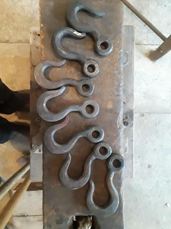
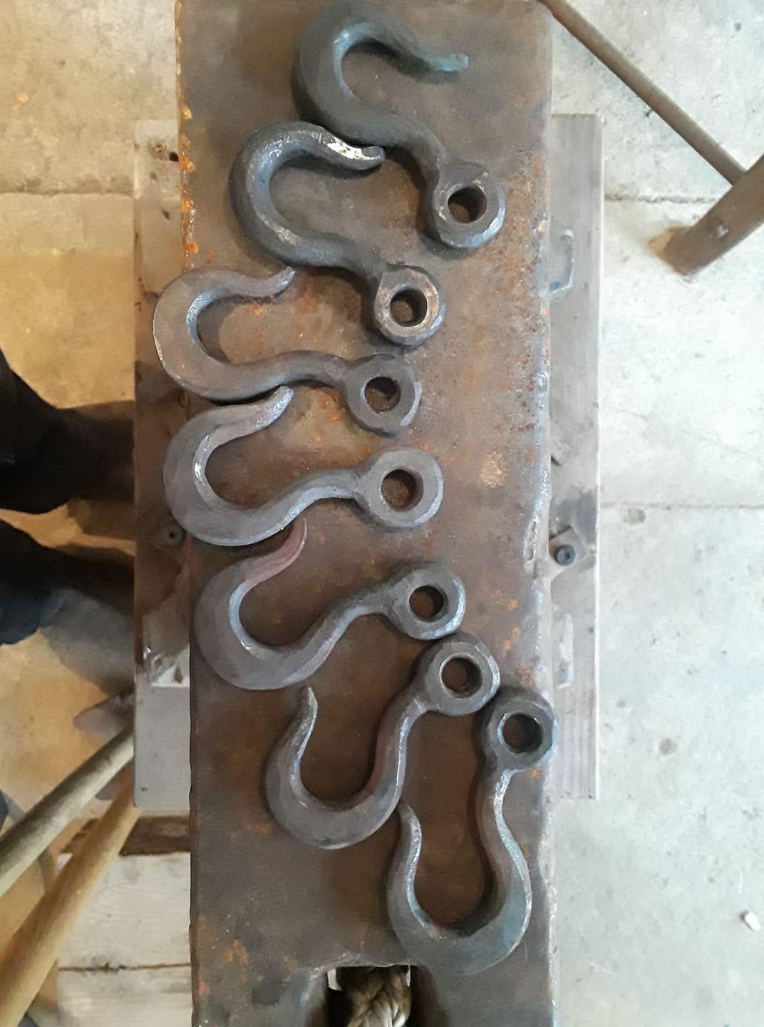
I make hooks sometimes at public demos. I'm aiming for consistent forms from 3/4" round stock. No swage, just a hammer, anvil and punch. I like the proportions of the ones you've shared here.
-
Hi Glenn, I have a few things on wheels, but my goal is to avoid them. I've spent too much time in shops where things move and wiggle about. It comes somewhat at the cost of circulation space, but I'd rather have fewer tools than constantly be shuffling things around. It's not a shop that can do everything, but it suits the way I work I have wheels on the obvious things: welder, oxy acetylene rig, forge, bandsaw and my fabrication table which can dock against my platten table to extend my layout space. Frosty, The dashed lines are overhead beams. In the pacific northwest I have condensation problems aplenty, rust will be a constant battle. The machine tools were precise in 1920...I don't pretend to be a real machinist. I just make basic tooling for my purposes. Nice of you to actually evaluate the layout, I appreciate that. -A.
-
My disorganization has finally led me to a complete shop overhaul. The only thing fixed was my power hammer. I decided nearly every other item had to move to improve my efficiency. It took most of the afternoon to move everything, and it took twice that long to lay it out, but I can tell it is going to pay off. I post here just to encourage people to make as accurate a drawing as they can and test everything from the handle swing on a hossfeld to outlet or lighting locations.
.thumb.jpg.e573d049415cd4d4816362c10a05026d.jpg)
-
Goods, Very constructive suggestions, thank you. The keyway is a great idea, it need not be deep to be effective. -Adair
-
Frosty, Bolting from the top does make sense for various reasons. Thank you for the suggestion. Jim Coke, I strongly disagree with your assertion and find your conclusion pretty limiting. Finding terminology to describe the processes for forging plate into vessels seems elusive sometimes (as evidenced by this meandering discussion thread). I suspect we are just visualizing something different. I do this work already (though inverted) with both sledge on anvil and set tool on my Litle Giant. I posted earlier on this thread of the same process done with a water powered tilt hammer. I just need more room to move the work around on the Little Giant. No shortage of control with the machine. -A.
-
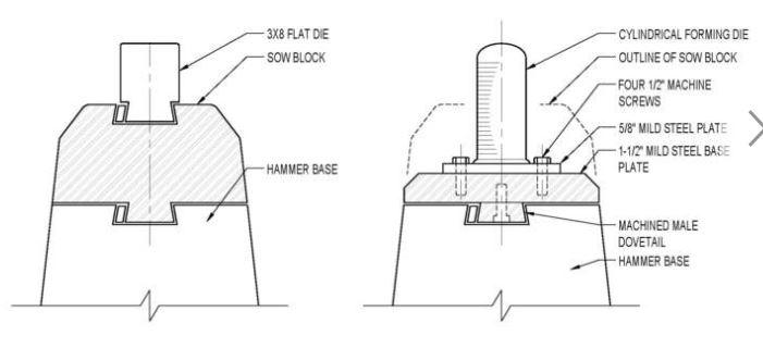
Frosty, Negative. Please ignore those images. I am referring to the last image posted. The one with the note identifying "cylindrical forming die". (It's photobucket, I don't know if everyone can still see it). I just want to make a shallow sow block but don't want to machine it all from solid. I'd like to use 2" plate with a male dovetail bolted on. -Adair
-
I wanted to revive this thread in hope of receiving some input on one question: Is it wise to bolt on a dovetail on a 100# little giant per the lower right drawing in the above post? I'm imagining (4) 3/4" socket head cap screws up from the lower part of the dovetail
-
I've seen plenty of folks trying to sell junk to suckers, but the Craigslist ad I came across today was so upsetting. Someone took an anvil that must have had a hard life and milled the top right down to nothing. The horn and cutting table were ground down, and blended smoothly. The anvil was advertised as having no repairs and looked quite convincing, but anyone who has dripped sweat on an anvil would see the clues. Someone spent a lot of time on it. Hopefully someone purchases it for interior decor because I doubt there is a smidge of tool steel left on that face. As a beginner I might have gotten excited about a big anvil like this that looked clean and well cared for. I might have been suckered by such an advert. I feel fortunate that I had a few years working under other smiths before I could afford to buy any tools or get suckered by a con like this seller, I'm just sorry for the person with big dreams who pays top dollar for this one.


.jpg.5b3e261a17f136766dbe01379a4fe754.jpg)