Adair
-
Posts
96 -
Joined
-
Last visited
Content Type
Profiles
Forums
Articles
Gallery
Downloads
Events
Everything posted by Adair
-

4140 dies turned out to not be 4140. What next?
Adair replied to Adair's topic in Heat Treating, general discussion
Thank you both for helping me face the reality. I asked them to just send the dies back. We'll see how long they hold up pounding cold sheetmetal. I'll be curious until the end of time what steel I actually purchased. It was soooo long ago. The first tool steel I ever paid for. -Adair -
Hello all, I sent some dies to a heat treat shop. I had 4140 written on the steel. I have a few hundred dollars invested in machining. They were heat treated but do not test above 45 Hrc. I was after 54 Hrc. The representative in the shop thought they behaved like 4130. He can case harden them but these dies are for cold work (sheet metal power hammer). Is there any prudent next step that I might be able to take. I bought the steel new but it was 20 years ago. I must have mislabeled it. -Adair
-
My first guess was a sawyer's hammer. Your explanation reinforced my conclusion. It's light compared to many sawyer's hammers I've seen, but the opposed, wide peins look correct. -Adair
-
U.S. Army (Cavalry) pack forge
Adair replied to Irondragon Forge ClayWorks's topic in Solid Fuel Forges
Iron Dragon, Thanks a million. This forge belonged to my friends grandfather and he would like to be able to use it again. Very interesting to know that it was welded. I was hoping to rivet the corners! -Adair -
U.S. Army (Cavalry) pack forge
Adair replied to Irondragon Forge ClayWorks's topic in Solid Fuel Forges
Irondragon, I would really appreciate that if you have the time. Thank you. In the attached image you can see what is left of the forge I've been asked to reconstruct. -Adair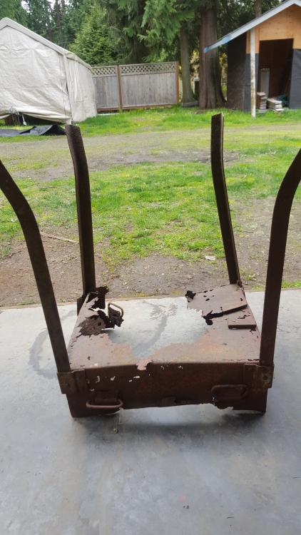
-
U.S. Army (Cavalry) pack forge
Adair replied to Irondragon Forge ClayWorks's topic in Solid Fuel Forges
Hello, A friend has asked me to reconstruct a forge identical to this one. There is next to nothing left of the box and lid, but the hardware and legs are all intact. I was hoping I could get a measurement of the thickness of the sheet metal used so that I can have a new one brake formed. Any chance you could provide that? -Adair -
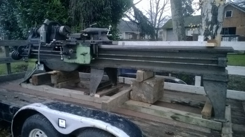
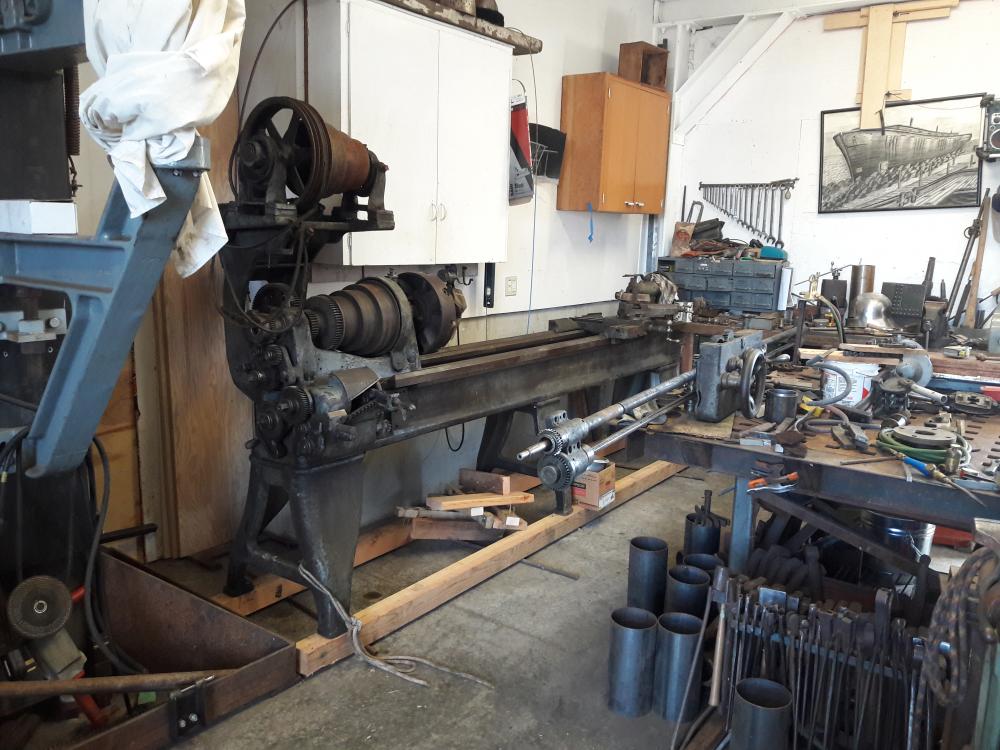
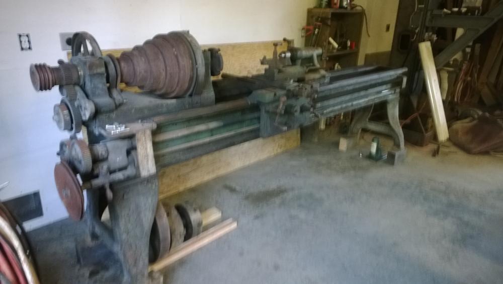
Since I started this thread quite a while back, I'll share what I wound up with. I started out with an 18" Greaves & Klussman that was a project lathe. It had no countershaft, no transmission and was quite worn. I worked on it for a while and then came across a 20" leBlond. It was turn-key, but it was a gap bed which had real limitations since 99% of my work would be up close to the chuck. It was also far more lathe than I needed. Ultimately an 18" ATW lathe appeared at my local salvage yard. It was all disassembled, but I was able to trade my Greaves & Klussman for it. It has a QC gearbox, a countershaft motor mount, double back gears and much less wear. I have it mostly assembled and all parts appear to be present. It's taken a while to wind up with the right lathe. I did save a good lathe from a sad fate, though I resigned another one to the same. The big LeBlond ways will become a mighty workbench. It took some patience until the right one came along, but all three were nearly free.
-
Quilbilly, For what it's worth, 4". As Jeremy K stated, I change the crosshead position on the Pittman as needed. A.
-
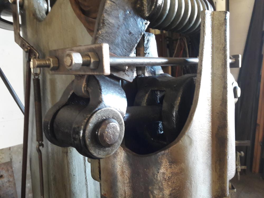
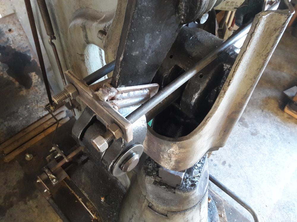
Beaudry, Ha, it may make the engineerring-minded laugh. I have always hated little giant treadles. I made my own that is balanced with minimal slop in the linkage to reduce treadle stroke and the resulting flamingo dance. The parts you see are pillow blocks to make the pivot points wide to reduce twisting. There are twin tubular push rods that go up each side of the frame. They are actuated by a lever that extends from the treadle behind the hammer. They push up on the clutch arm rather than pull down as the original did. I built a new clutch arm with a lever running the opposite direction to make that possible. I love it because the action feels like a large air hammer, but I am not a gifted fabricator. -A.
-
Ugly, but it gets the job done. It can't slip any direction. The tapered cross section of those toggle arms makes any other clamping solution pretty sketchy. -A.
-
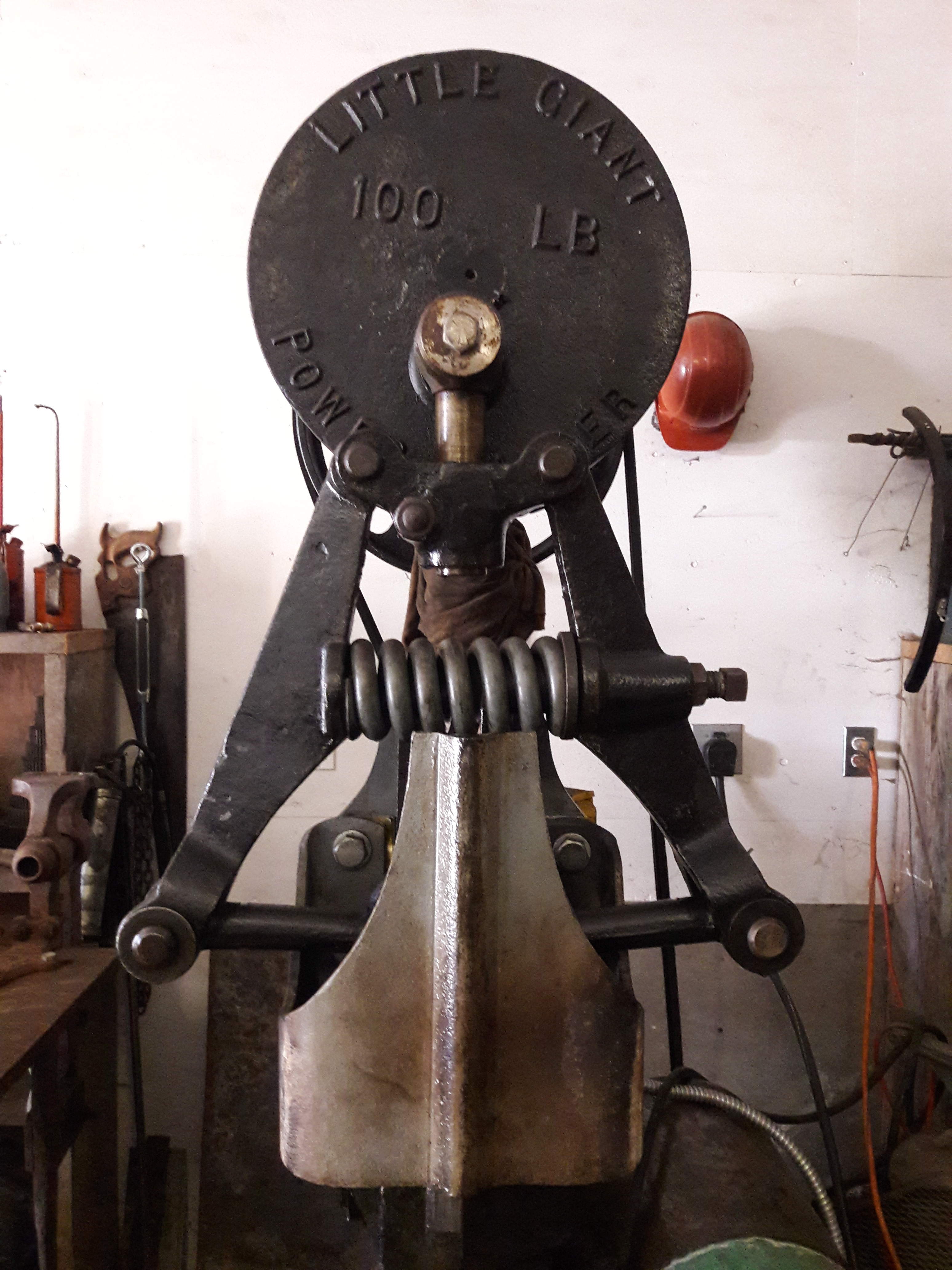
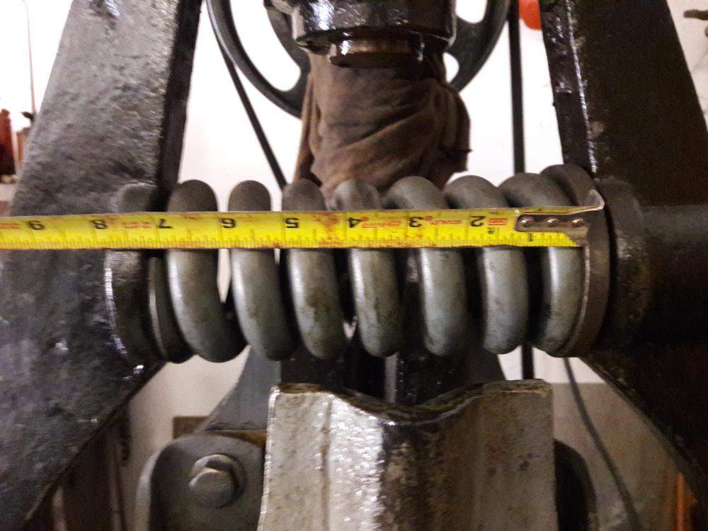
Todd, I grabbed a photo of the spring. As compressed (leaving about 1-1/2" gap between dies at rest) the spring is 7-1/4" long. It feels a bit tight to me when I'm running hard. I've worked under at least three other 100# LGs over the years for comparison. With the clutch fully engaged, it feels like the links are already pulling up on the ram before it has transferred all its energy to the work. I bet if I could back the spring off just a hair more all would be in order. Beaudry, I confess, the lack of a spring guard is due simply to laziness on my part. It's as careless as not putting on a seatbelt. As for the brake; I did turn my crank plate on a lathe when I acquired it so that I could easily fit a brake strap. It's on the list.

-
I have the exact same hammer. I will check on measurements. The spring I have was purchased from Little Giant 20 years ago. I made a compressing clamp to securely pull the toggle arms together while I pin the toggle links. I did it once with multiple pipe clamps, but that was sketchy. There are so few surfaces to gain purchase on. -Adair
-
I've always loved the narrow face and long horn on these anvils. They may not be the most effective distribution of mass for a general forging anvil, but they sure have shapely proportions. -Adair
-
something i've been working
Adair replied to The Rusty Forge's topic in Blacksmithing, General Discussion
First of all, congratulations on getting a fire going and having some quality forge time. I hope you don't mind some constructive criticism about your posture. I offer it because it pains my lower back to see you hunched over like that. A lot of beginning smiths do what you are doing. I believe they want their eyes close to the work and their body far from it. Some also insist on their body always being square to the work. My advice is step up to that anvil and get your body over the work. You will save your back, save your muscles, and improve accuracy and endurance. Swinging as the photo shows, you are expending a lot of energy to hold that hammer in the air at arms length from your center. -Adair -
The best tip I can give for public demonstrations, and this is really crucial when your audience is random: Demonstrate items that you can forge in your sleep. Confident, linear processes from beginning to end are infinitely more captivating than fussing and tapping as you try to work out something new Additionally, a well rehearsed operation will free up your mind to interact with the crowd while you forge. That is a skill in itself I've found. I'll make the same product repeatedly, striving to make each one like the next. If you can dictate what you are doing while you are doing it, and wind up with consistent, quality products, you will be honing your own skills in addition to entertaining the crowd. That determined certainty about every move is really apparent, even to someone who has never seen a blacksmith work. -Adair
-
Little Giant Sow Block tooling
Adair replied to Adair's topic in Power Hammers, Treadle Hammers, Olivers
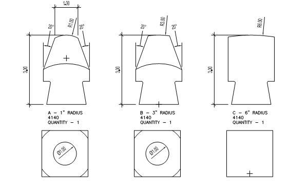
Here is a better sketch of what I would like to build. Would drilling and counter-boring for large machine screws be sufficient to attach the male dovetail? -A -
Little Giant Sow Block tooling
Adair replied to Adair's topic in Power Hammers, Treadle Hammers, Olivers
I finally have my little giant in condition where I can make good use of it. I'm revisiting this idea I hatched while the machine sat. It looks like all my previous image links are broken, I wish I could go back and correct the links. I just had to organize the images I had in Photobucket and that messed everything up. I'd like to make a tool holder that replaces the sow block similar to the attached sketch I made (the image on the right in the first photo, the image in the center in the second sketch). The die height would match the normal bottom die and would not affect the performance of the machine. I have a piece of 1-1/2" plate burned to the outside diameter of the hammer base where the sow block mounts. I would like advise on two things: 1. How can I best attach a male dovetail to my baseplate? I don't want a weak connection here, but I can't afford to machine this from solid. 2. Should the base of the dovetail "bottom out" in the casting, or should the "shoulder" of the base plate bear on the machined surface from which the dovetail is inset? Cheers, Adair -
100# Little Giant diagnosis
Adair replied to Adair's topic in Power Hammers, Treadle Hammers, Olivers
-
100# Little Giant diagnosis
Adair replied to Adair's topic in Power Hammers, Treadle Hammers, Olivers
I've had time to make some headway on this project again. As shown above I was convinced that three of the holes of the wrap-around guide were simply in the wrong location. I machined some plugs and welded them in place, filling those holes. I had to anneal the plate after that. I mounted the guide back on the hammer and aligned everything as accurately as I could manage with shims. I made a tool to transfer punch the holes from the cast frame to the wrap-around guide. Once drilled, the bolts slid right into place and with the shims I had made the ram moved very smoothly in the ways. I believe that problem is solved. I have a little bit of shimming to make it perfect, but I am encouraged by the progress. The hammer runs with good control. I have one lingering issue to deal with. I am having trouble verifying it, but the centerline of the toggle arms, toggle links, and ram do not appear to my eye to be coplanar. In other words, I think the connecting links are raked slightly backwards towards the frame. As ever, I don't know how to verify this. With all the slop in the wrist pins and crosshead, it doesn't appear to affect the motion. -
100# Little Giant diagnosis
Adair replied to Adair's topic in Power Hammers, Treadle Hammers, Olivers
Kubiack, Thanks for you input, but no amount of shimming can correct this. If one were standing facing the hammer, the front way is rotated counterclockwise relative to the rear way. The only way to fix this is either to cut and weld the guide or to slot the bolt holes each by about 1/4" and rotate the guide around. -Adair -
100# Little Giant diagnosis
Adair replied to Adair's topic in Power Hammers, Treadle Hammers, Olivers
OK gang, I've discovered or confirmed a bit more of the problem with my guide. I believe I have verified that the front way is twisted relative to the rear way. The following photos should show what I've found With the guide sitting on my platten table, the bolting surfaces are perpendicular to the table on two axis. The v surfaces of the front guide however are out of perpendicular. The top right is 3/16" out and the bottom left is 3/16" out. I checked the bolt hole positions to see if their plumb line was perpendicular to the table. They were not. They are at least 3/16" out of plumb. I don't know if the latter observation counts for anything because who knows if the holes in the casting are plumb. To cross reference I placed the guide tight to the ram, so that all bearing surfaces were mated. I aligned one bolt hole on the left side. The right side holes were nowhere near alignment. This verifies to me that the front guide is badly twisted relative to the rear. The only other variable would be if the ram guides were not co-axial. I don't know how to check that, but it seems less likely. I tried putting a strain on the top of the guide with a pipe clamp and heating the sides of the guide, then letting it cool. This is not working. I can't imagine another way to apply force to this thing. It is very hard to manipulate in place. My only other thought is to cut the front of the guide off, grind full bevels. align the front guide with clamps, and weld the grooves. I'm sure there will be a lot of movement at the welds, but maybe they will balance out as they cool together. Thoughts? There really is no wear at all on these surfaces. This hammer must have been out of whack since day one. It certainly was not used much and maybe this is why. -
100# Little Giant diagnosis
Adair replied to Adair's topic in Power Hammers, Treadle Hammers, Olivers
I am struggling with getting this guide aligned. It appears to me to be twisted. The photo above shows the gap on the top left side of the front way. As far as I can tell there is full contact at the low end of the front way. It's impossible to see under there. I've had heat on it, but I think that is too much steel for my #4 MFA rosebud. What I think has to happen is to coerce the top "horn" of the front way to the right. Not sure how to go about doing that without making some mighty big clamping jig and finding a bigger heat source. I'd have to heat a lot of 1/2" steel to make that thing twist. Am I even certain that the ram is sitting square to the frame? I have it clamped to the rear ways, but there is no reference point on this machine. -Adair -
100# Little Giant diagnosis
Adair replied to Adair's topic in Power Hammers, Treadle Hammers, Olivers
Attached is a photo of the treadle I built. I've always hated the hoop style treadle with its tendency to twist. This treadle is counterbalanced and connected in back by a keyed shaft. I'm so broke right now I had to cut the keyways by hand. I'm excited about how much play this will remove from the system. Tonight I built an entirely new yoke and pivot for the spider. Looking forward to connecting these with adjustable, balanced pushrods. -Adair -
Clinton, That is a great tip. I looked at some of the scraps of wire from before I replaced the liner and the dualshield was really compressed and scarred with teeth marks from the rolls. I'm sure I had too much pressure to correct for a friction problem in the liner. -Adair
-
IronWolf, the dual shield is indeed .045. I found an old liner that I had changed out but decided not to throw away. I swapped them out and adjusted the alignment as best as I've learned. The welder worked flawlessly. I can't see that the old liner has a kink in it, but I'm going to bet that the little nub that sticks out towards the rolls was misaligned during one of the pile ups and took a set. Thanks all for the input. Happy to have a better understanding of how to balance this out. I bet it all started by too much pressure with the rolls. -Adair