Ed Steinkirchner
Members
-
Joined
-
Last visited
Everything posted by Ed Steinkirchner
-
i considered alternative things to the crank that would eliminate the side to side movement but after alot of figuring i couldnt settle on a way that was strong,buildable with my equipment, and didnt exceed my headspace and footprint limitations. i figured that the problem witha scotch yoke is in that the yoke needs its own linear guide because the spring decouples it from the ram guide, and that would add too much height. outside of the height limitations i cant see any reason it wouldnt work
-
it has very good snap to the blows, i would say comparative to a 25# LG, maybe a touch stiffer but i thing things will soften up slightly with use. the full throw is about double the crank throw. So i would say the full throw is an additional 2-3 inches up and down beyond the 4 inch crank throw, for a total whip travel of the ram of about 8-10 inches frosty: i have a short video clip actually but i dont know how to post it here.
-
-
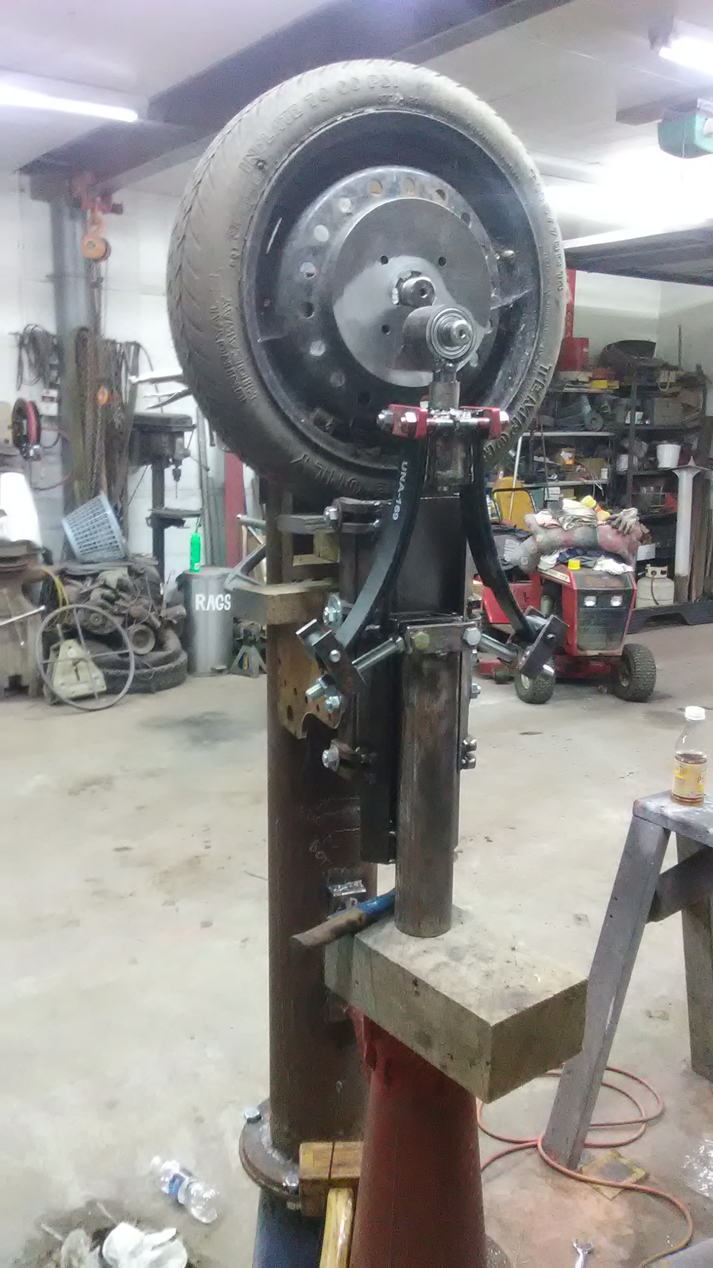
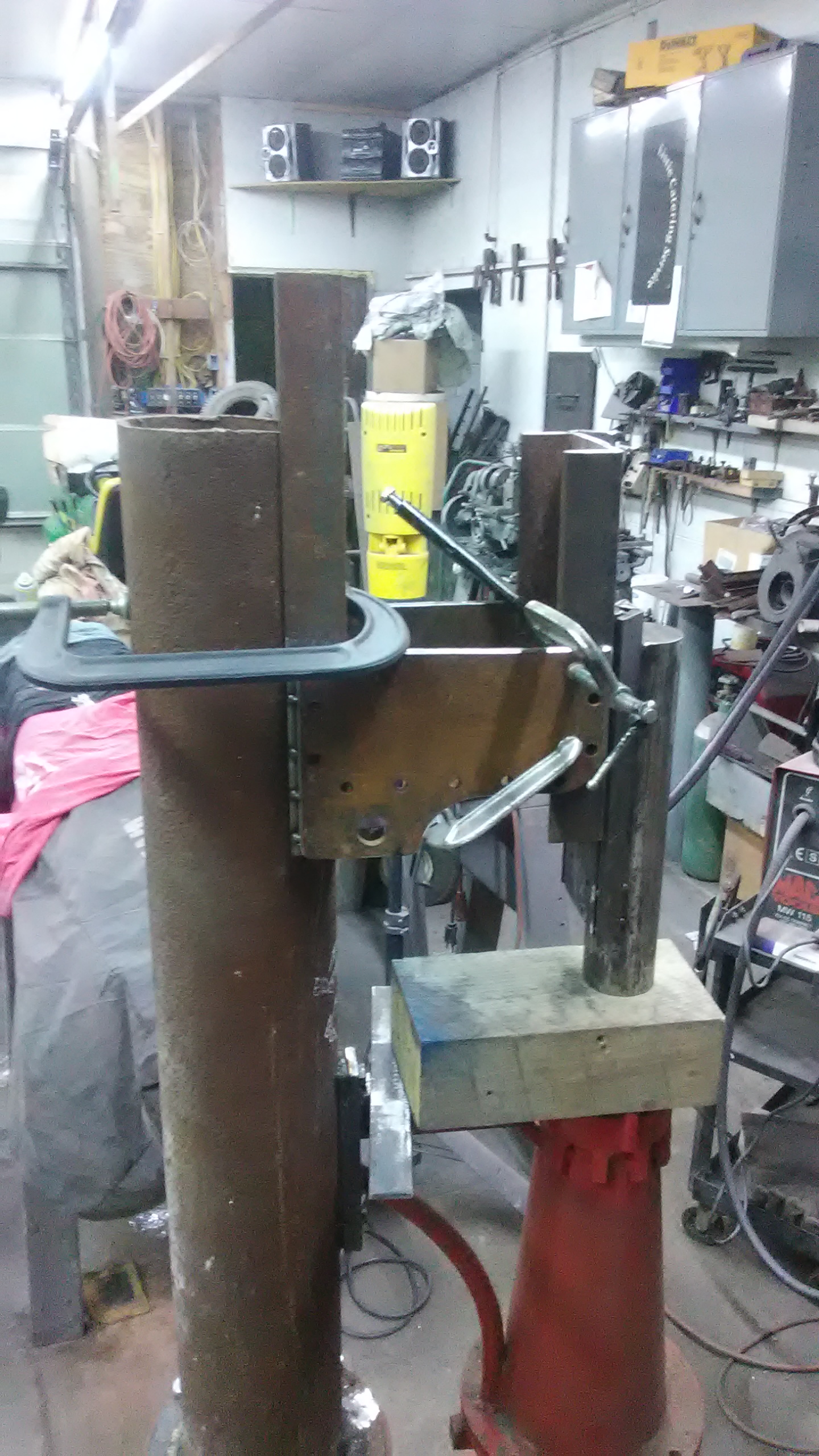
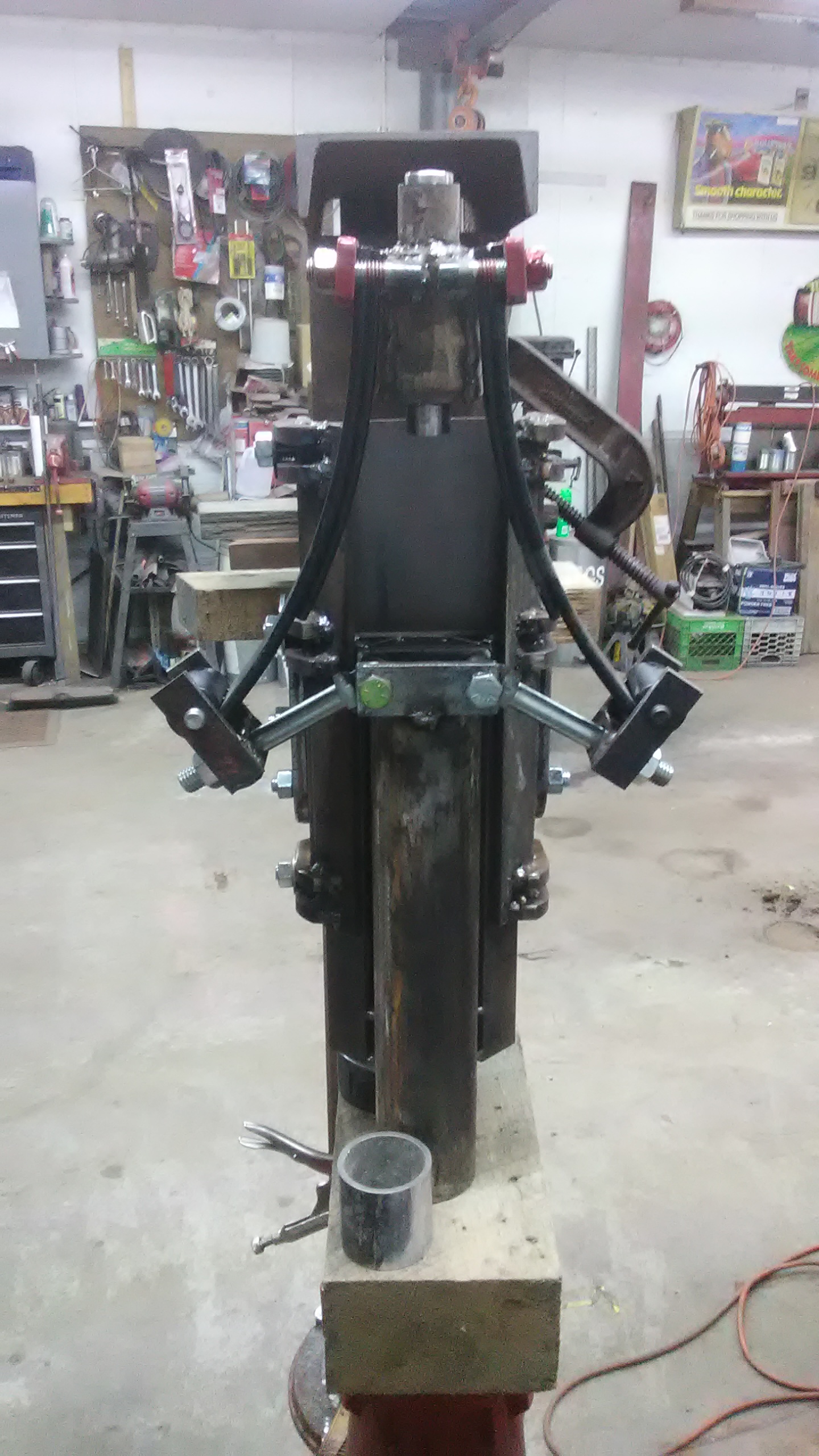
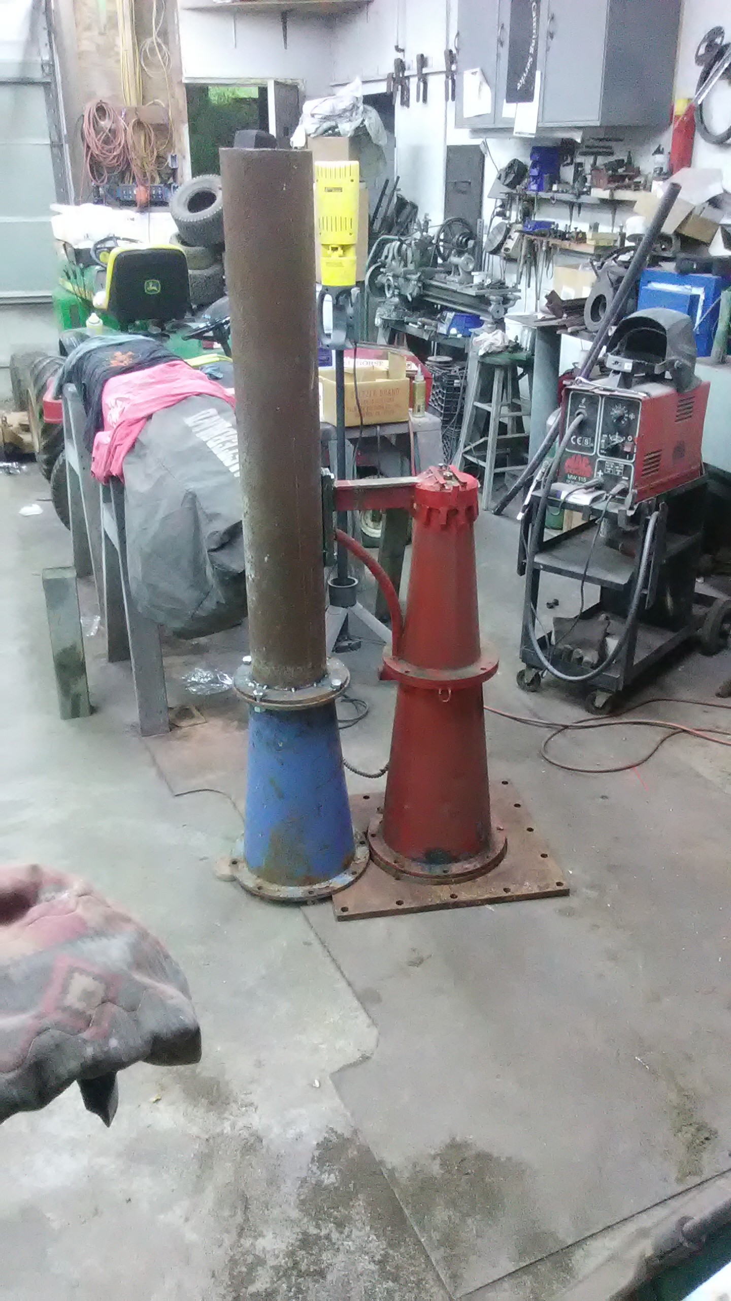
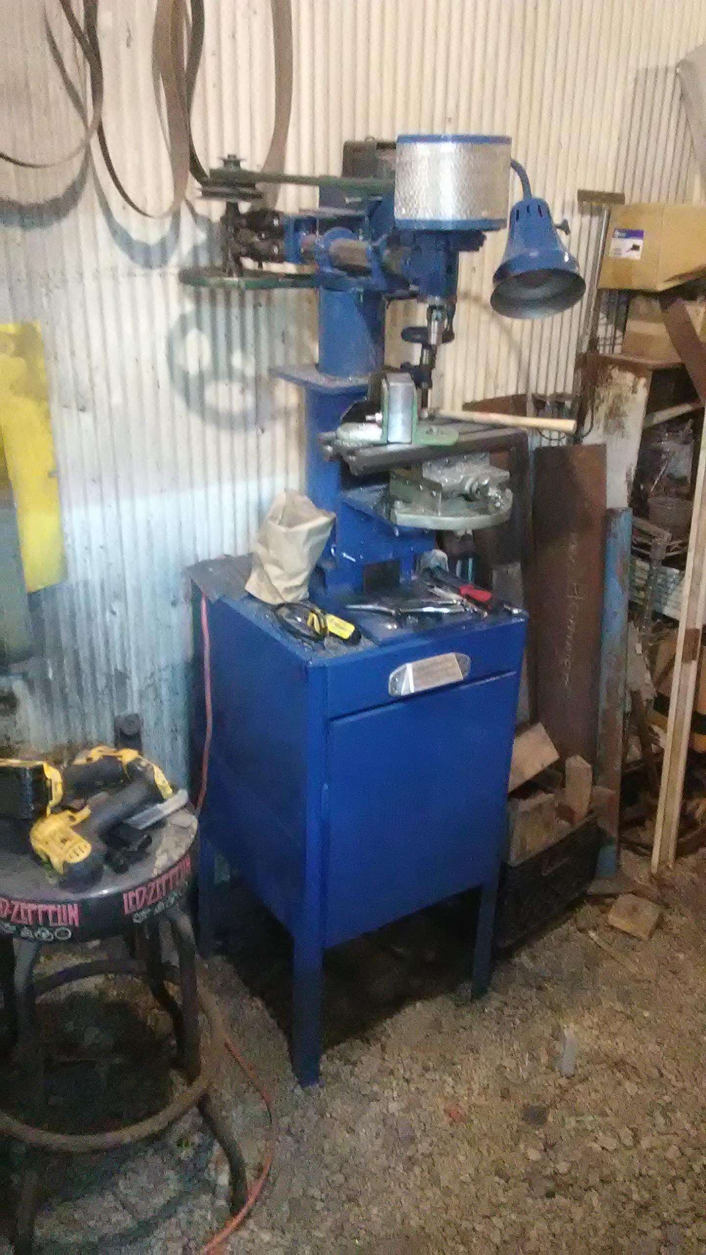
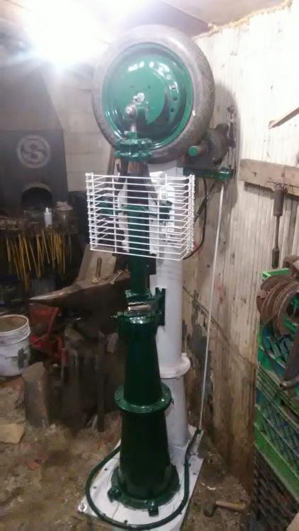
started this project around the end of august i believe, and managed to get it done about a week ago. instead of the normal tube in a tube construction of typical tire hammer tup/guides, i went with a 45 degree dovetail guide and ram, just to keep things as compact as possible to fit in my narrow and relatively low shop. i also deviated from normal tire hammer territory in the rotating assembly and crank sections. Instead of the trailor spindle i used pillow blocks and a 1.5 inch diameter shaft, in which was mounted a hub to carry the spare tire. The crank assembly is entirely separate from the wheel and hub, keyed to the shaft and removable allowing for replacement/rotation of the tire and rim in the future. Another noticeable difference, and the last major one, is the leaf spring dupont linkage (though i dont know is that still counts as a dupont) which i made by splitting a brand new small trailor spring and mounting each half in the orientation shown. a big consideration when building the hammer was the ability to disassemble it into pieces that could be moved with a dolly into the shop, so each part (except the anvil) is under 200 pounds. so here's the specs: tup weight is about 35 pounds, anvil is near 400, power is from a 1.5 HP single phase motor with a 1.5 inch pulley, the whole unit probably weighs about 1000 pounds, aand stands just over 7 feet tall. i will take more detailed pics tomorrow and dig up some progress pics as well. but i can honestly say that im extremely happy with its performance thus far!
-
i do the nick, quench, break thing myself but i add a step. After nicking it nearly through, i bend it about to 90 degrees then quench just the nicked portion so that the rest of the bar doesnt even touch the water just to minimize any chance at all of cooling.
-
i would use a narrow slot punch approximately 1 1/8 inch long and maybe 1/8inch thick , and after the hole is punched upset slightly then drift near final size before cleaning up the ring over the horn or a bickern.
-
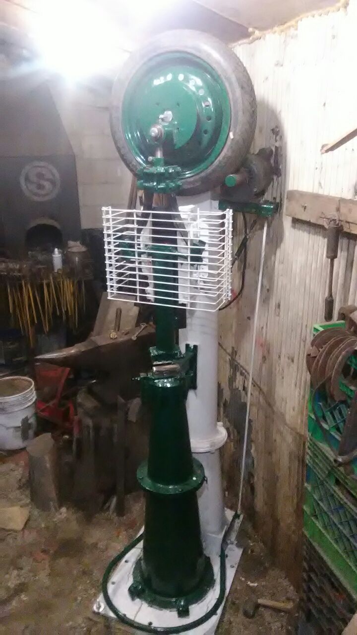
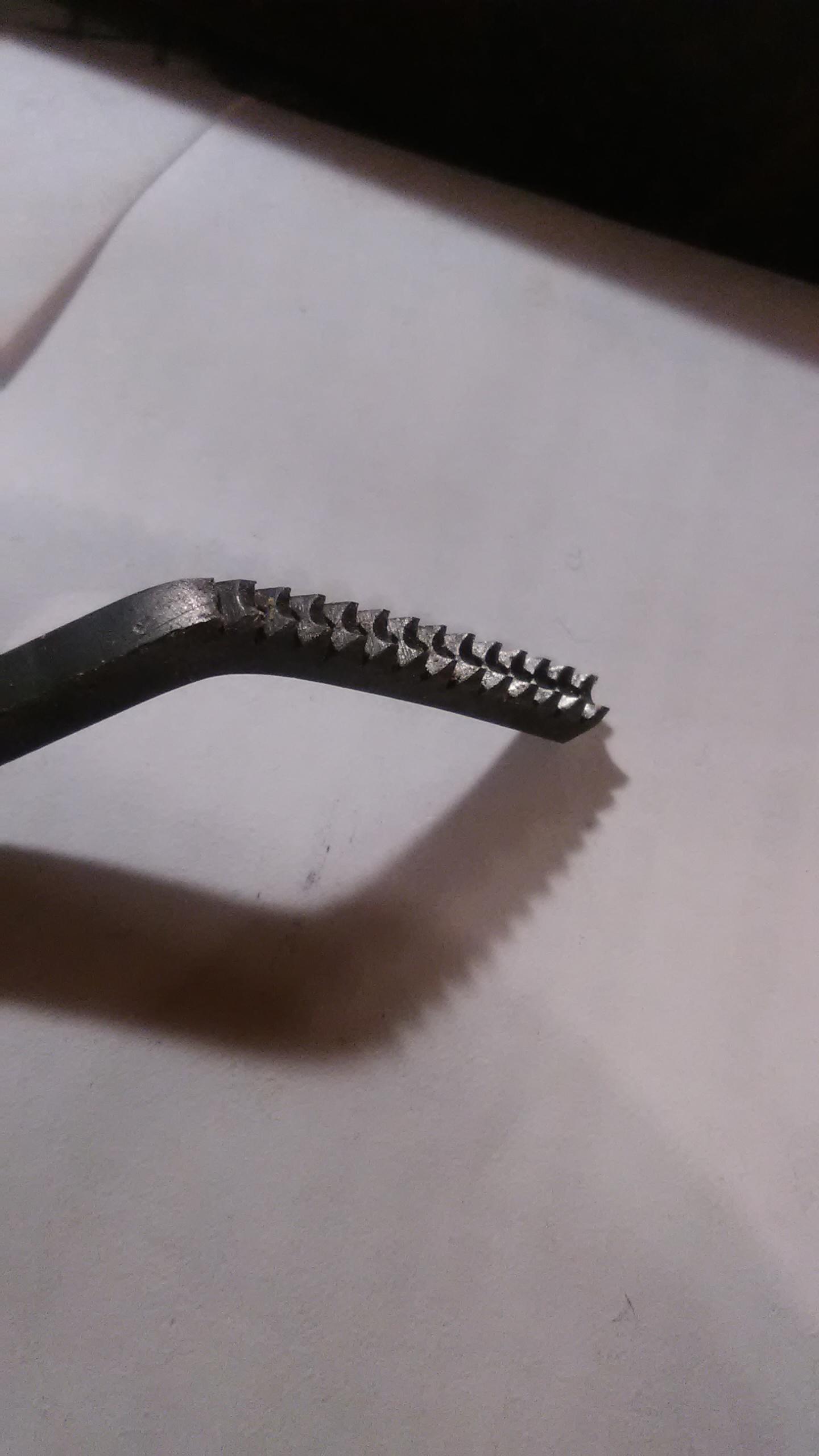
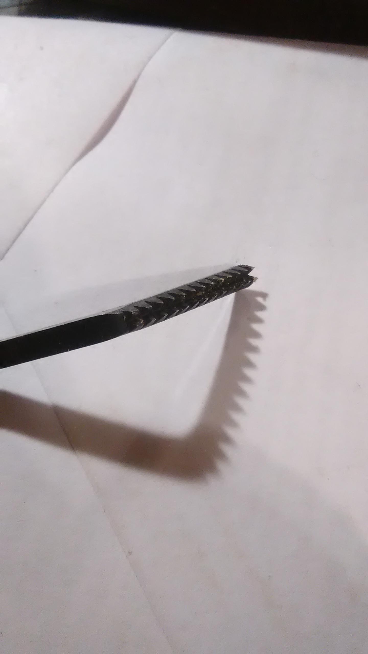
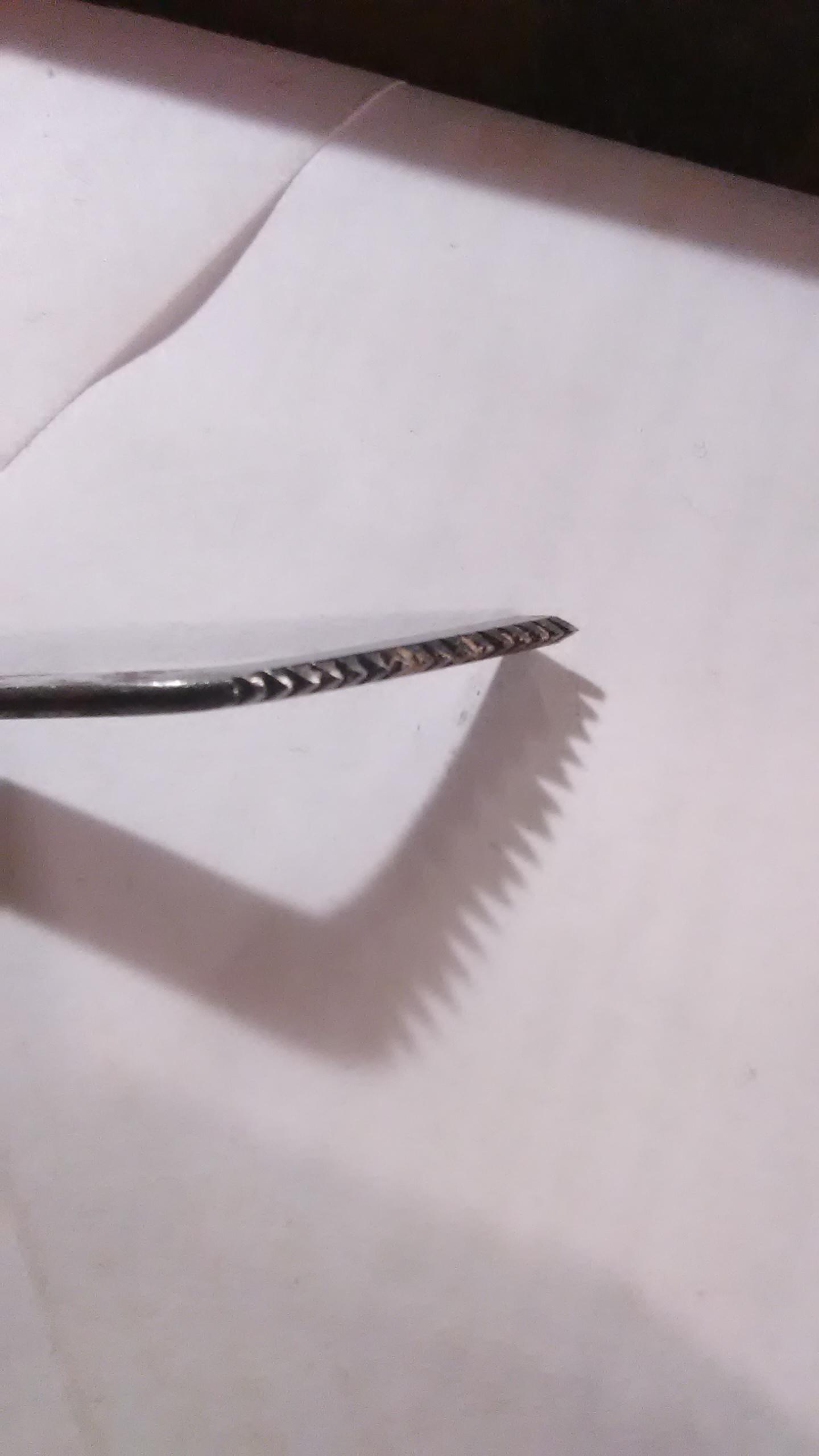
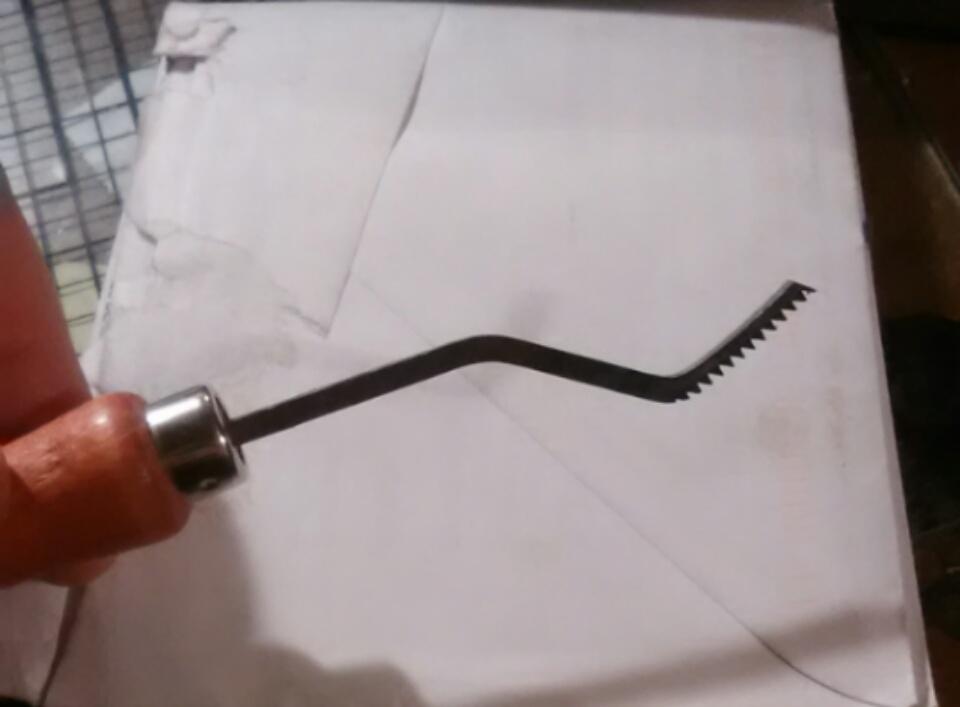
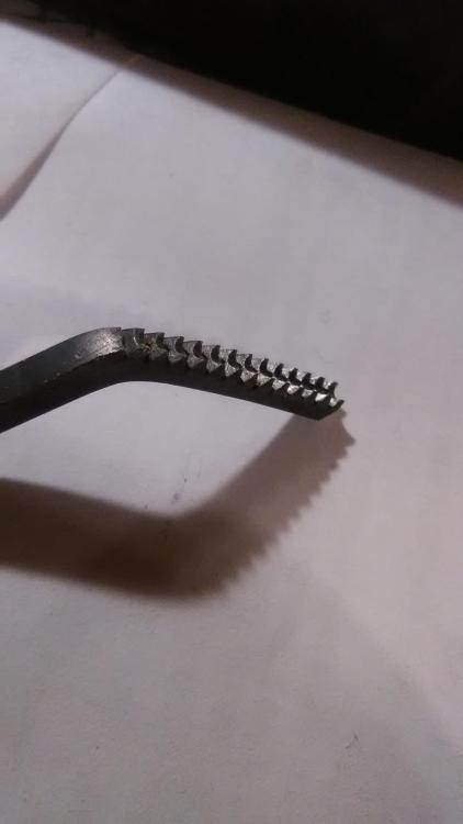
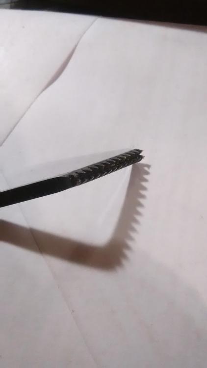
It's super late but for the sake of people reading this later who are wondering: these are the checkering tools i used, but this knife was the first thing i had ever done with them so it didnt turn out fantastic but it makes for a really nice grip which really helps avoid self inflicted injury! FYI its not smart to checker around something with an odd shape like this because the lines distort as they wrap around. the better way to go is to make the classic diamond shapes. I mean they exist that way for a reason as i learned! there are three cutters in my set, theyre used like a saw almost, rubbing them back and forth to cut the lines. you use the single wide one to cut the starting line then use one of the double ones to follow, one side riding in the previous groove and the parallel one cutting a new one, then you move to the next line and repeat. The tools in my small set are:The single line cutter, the narrow v cutter, and a slightly wider u shaped cutter. You should be able to imagine how they work by a glance at the pics. i think any semi competent Smith could make one of these tools once theyve used them

-
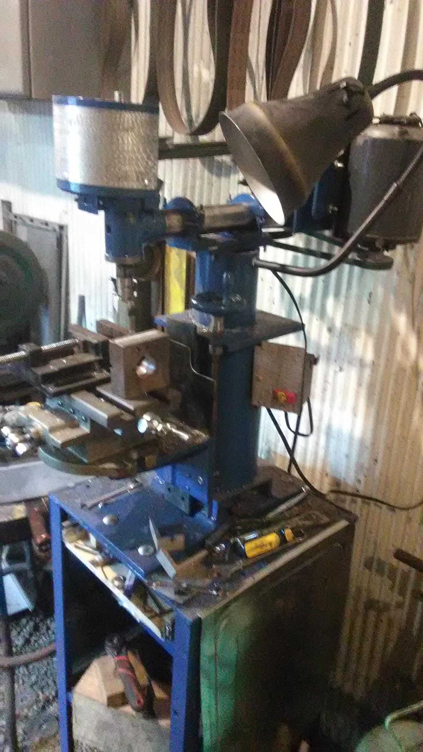
its as rigid as a 3/4" spindle can reasonably be expected to be honestly. the bearings have about .0005 or so runout but thats peanuts for what i do. rigidity is very good in the head assembly but the table isn't made as well as i would like and I've spent a good deal of time removing backlash and defects. What I'm going to do is use this table (in addition to hand scraping) to bootstrap my way up to a better made system. At that point the x/y table will be sent to the drill press where its more suited to purpose. Honestly the whole thing was done as a practice project to help me hone my machining and machine building skills in a way that would yield something useful in the process. If i just wanted or needed a mill, buying one would really be a simpler way to go!
-
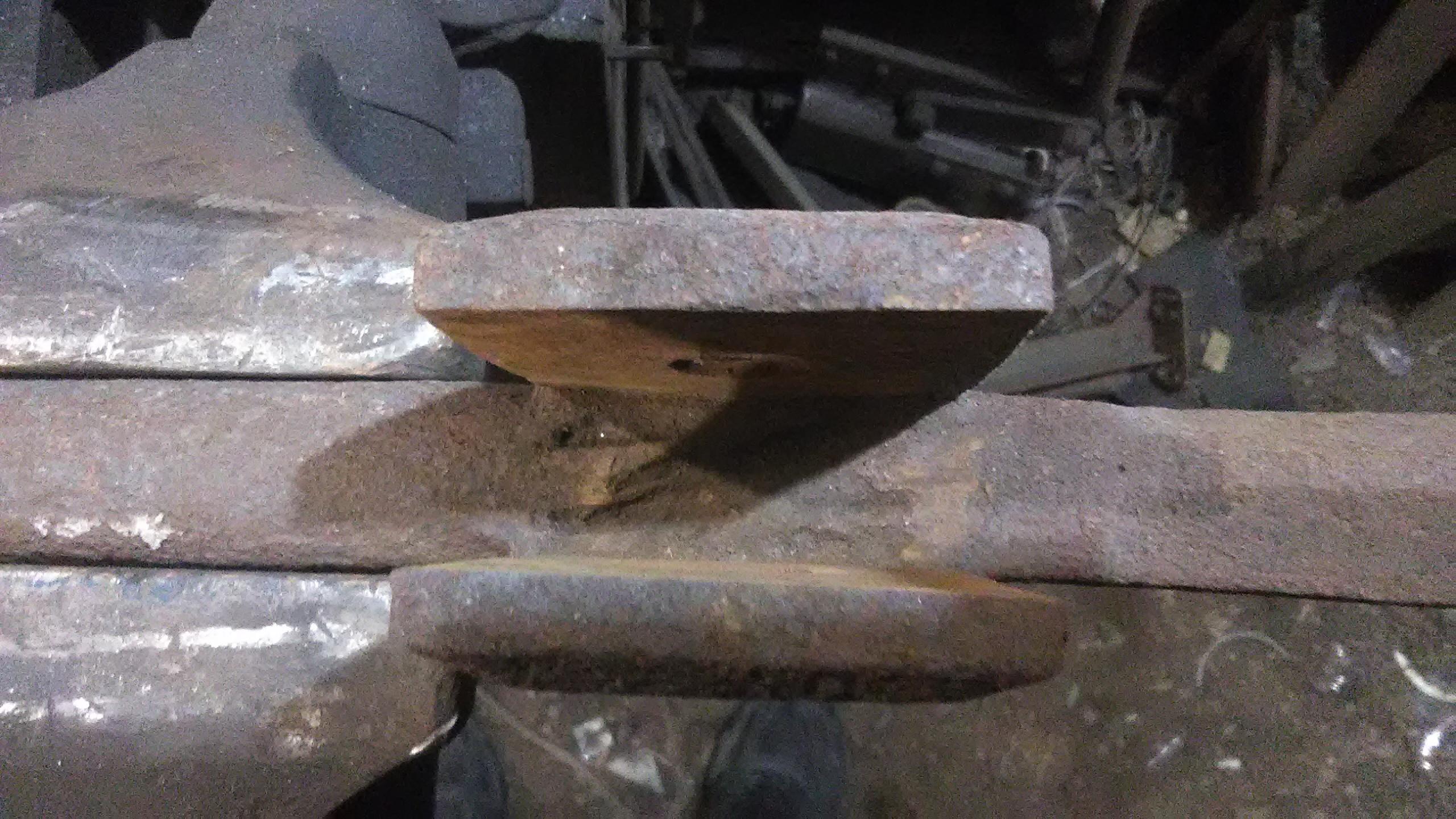
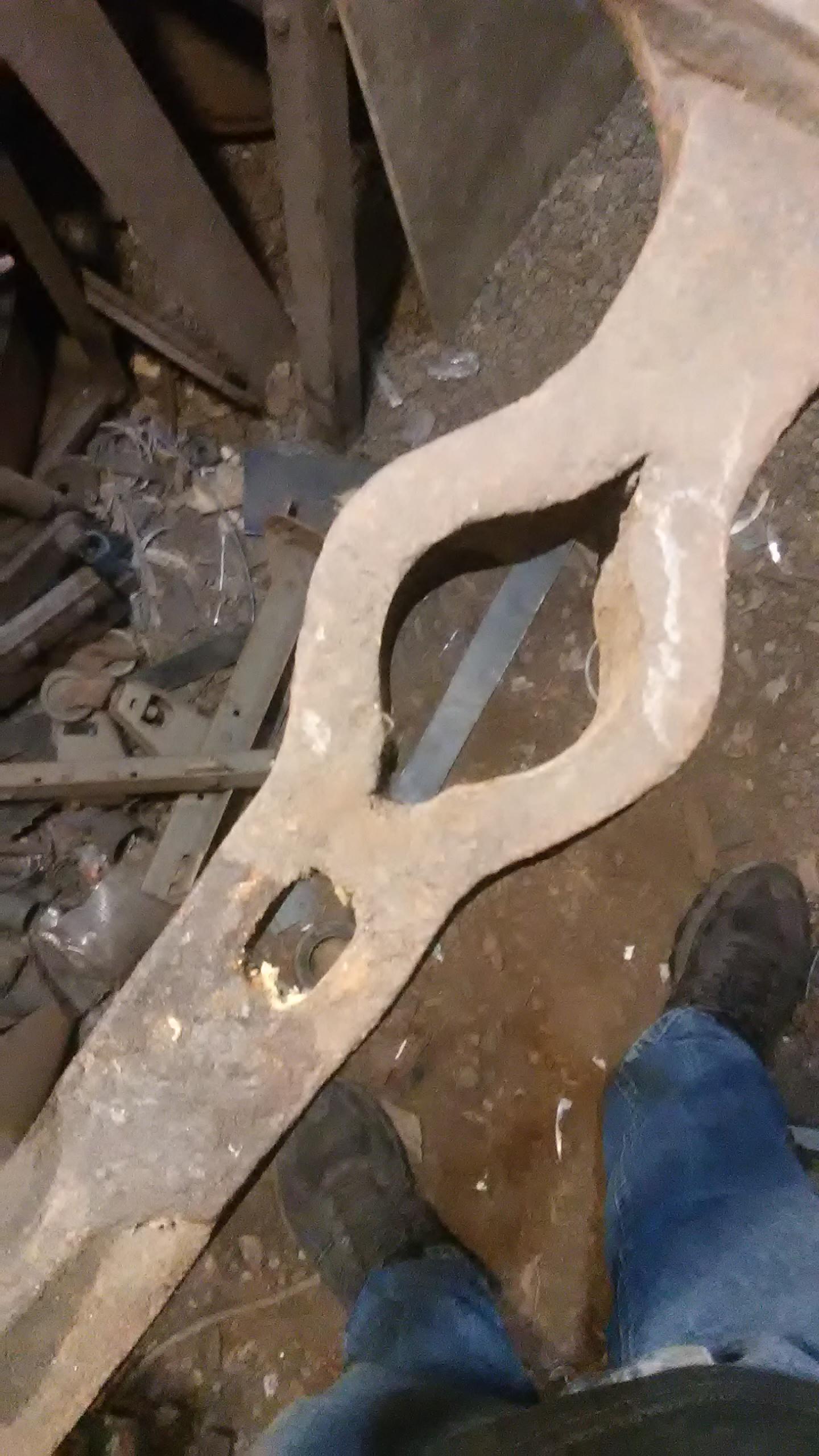
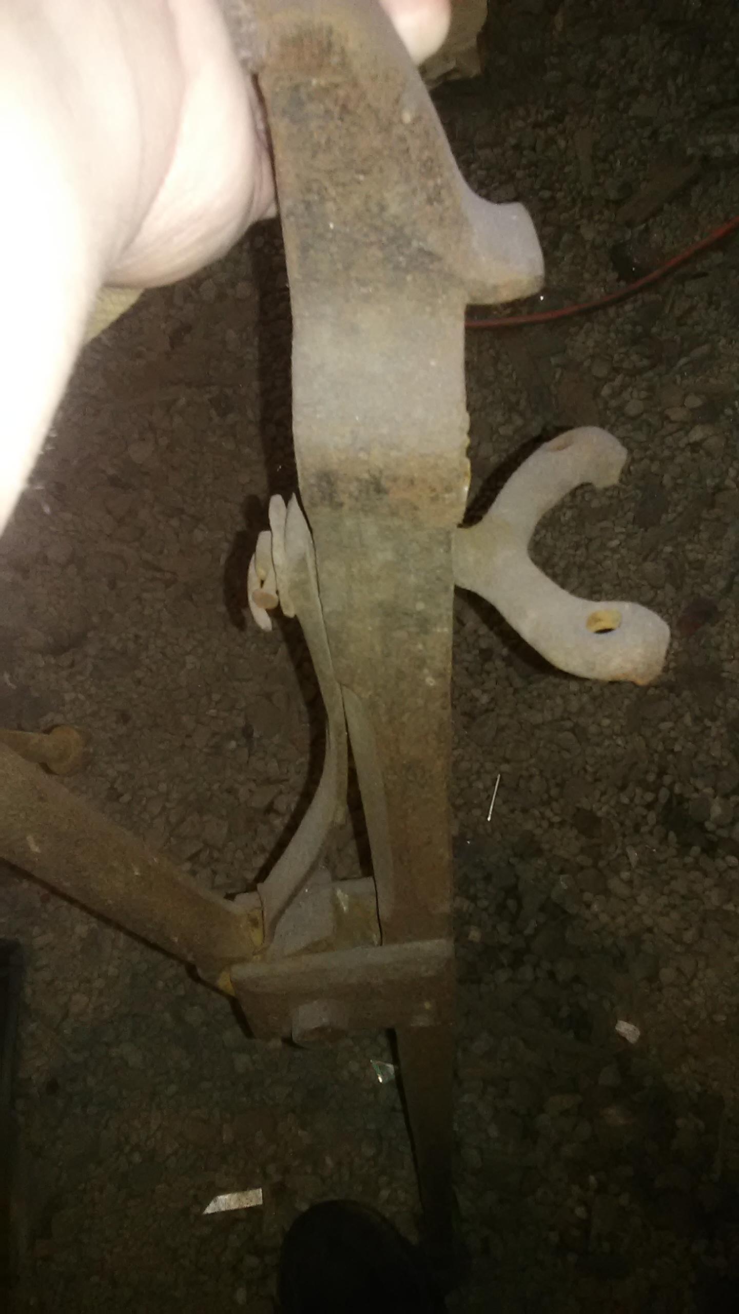
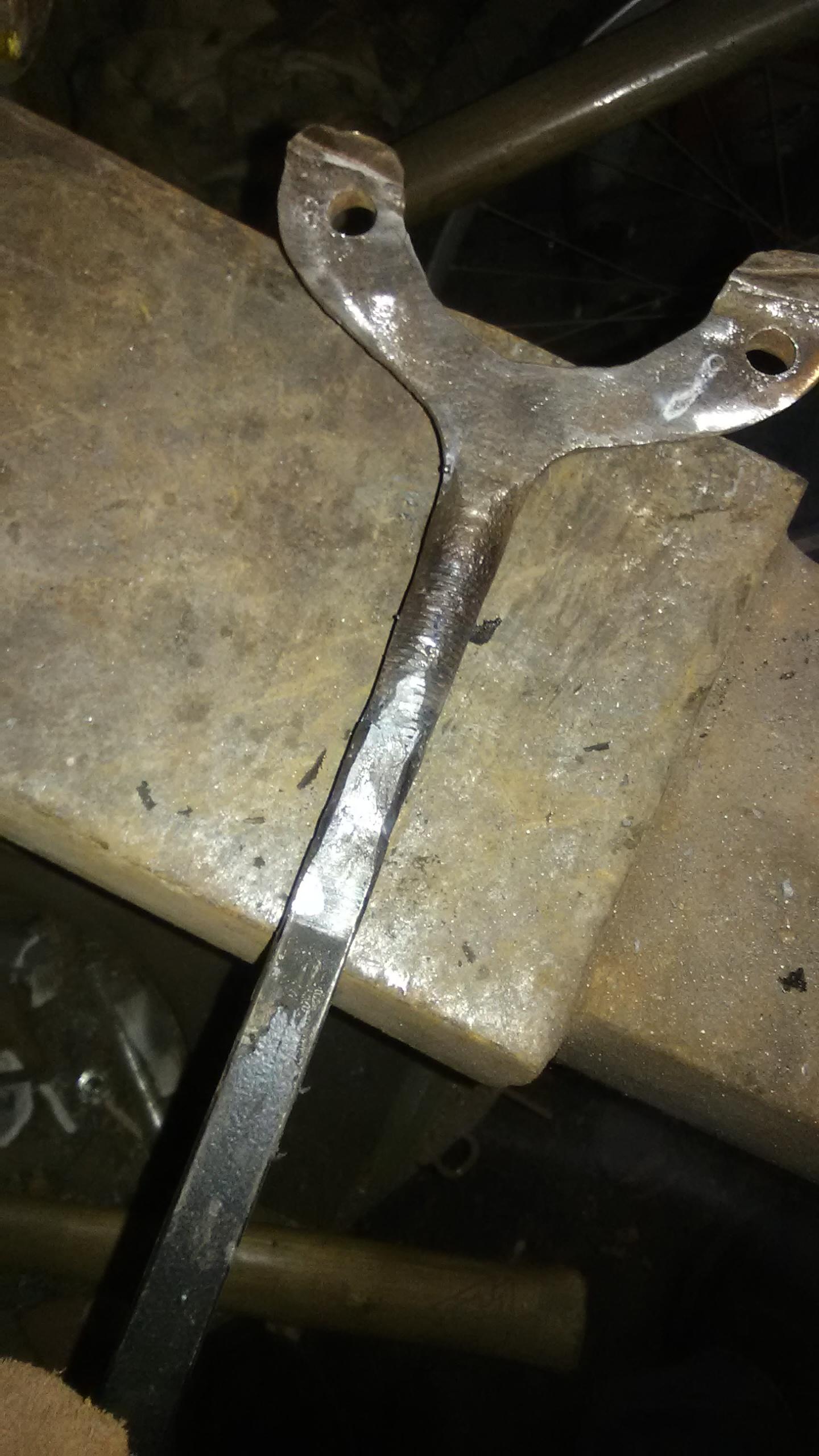
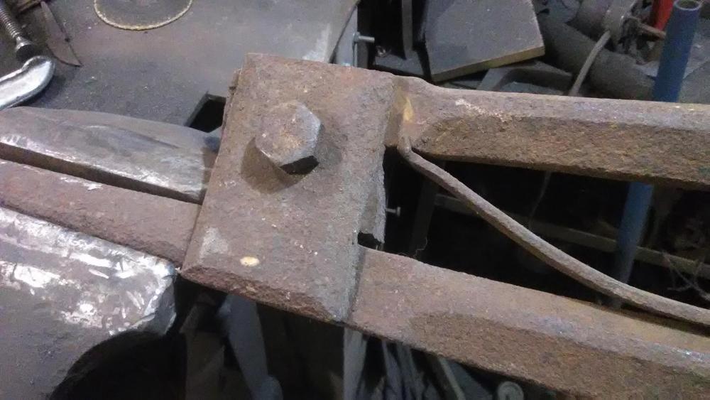
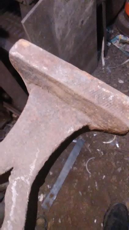
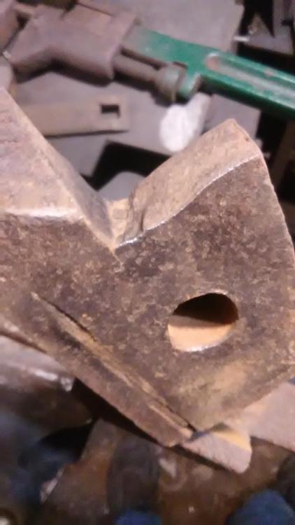
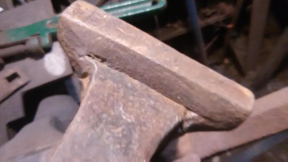
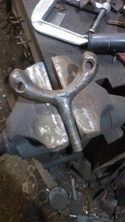
the more i look at this vise, the older it gets! i notice now that the front jaw is forge welded on and the hinge area of it has been doubled back and welded to add mass, plus the bevel forging of the shank between hinge and eye is not even, its about 10degrees off of being right, though it is square in cross section. also there appear to be fullering marks on the front hinge jaw pivot but im not sure their reason. As well the post side definitely has the "cheeks" of the hinge forge welded on and it has some deep fullering marks inbetween on the plates, i presume to mame sure the cheeks made good contact with the post. The hinge hole in one side of the cheeks has a small "key" i it which ive seen once or twice on other vises before to keep the bolt in position and prevent rotation , though the bolt is certainly not original. im intrested to see what electrolysis reveals when the rust is gone.


-
im curious now about how the bracket was attached. was it wedged on the spring side and have you shown pics of it in a post that i can search for by chance? Sounds interesting!
-
I'll show it in a seprate post when i get to that step probably but as a basic description, its a blue plastic barrel with the top cut off and a crude cage of scrap bars welded together around the outside as the one electrode (the workpiece is the other), and filled with water and a bit of calcium carbonate to make it conductive. then i use an old 12 volt battery charger as the power source.
-
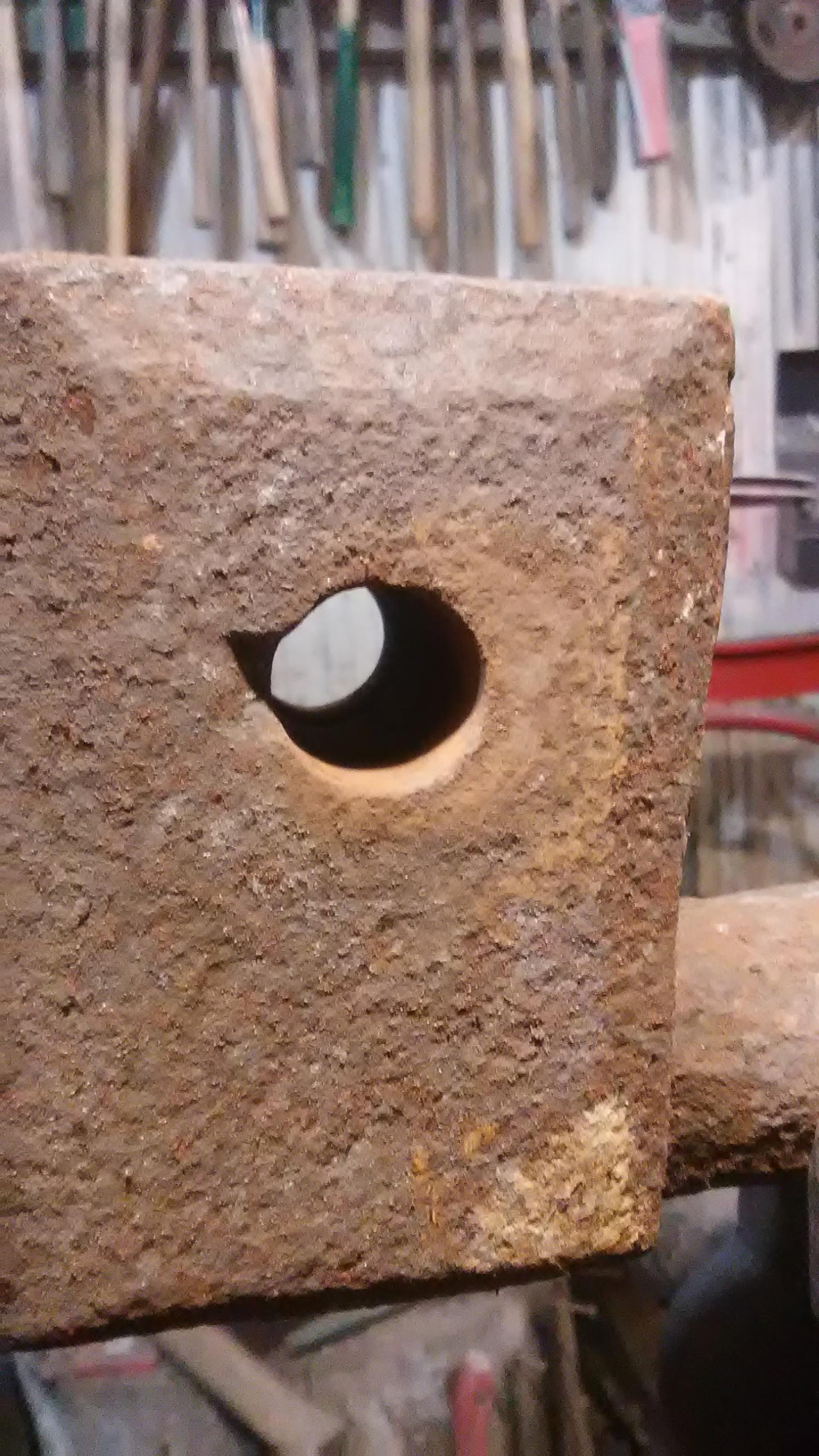
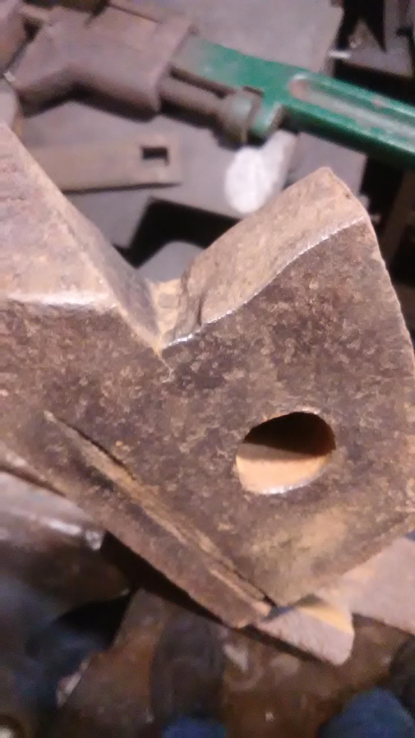
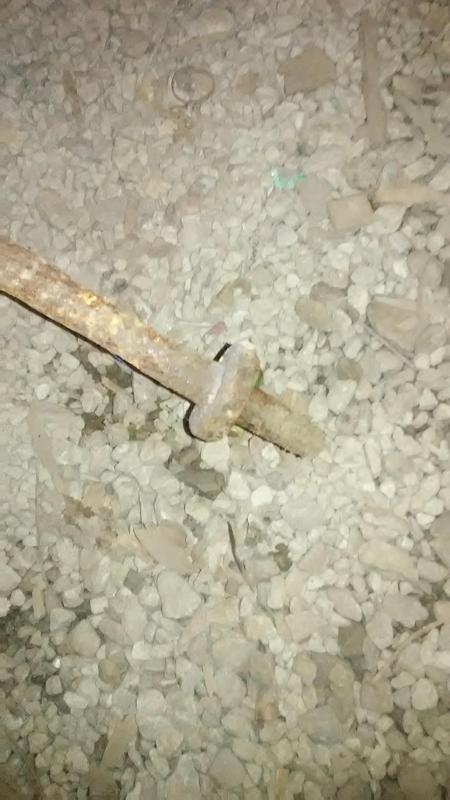
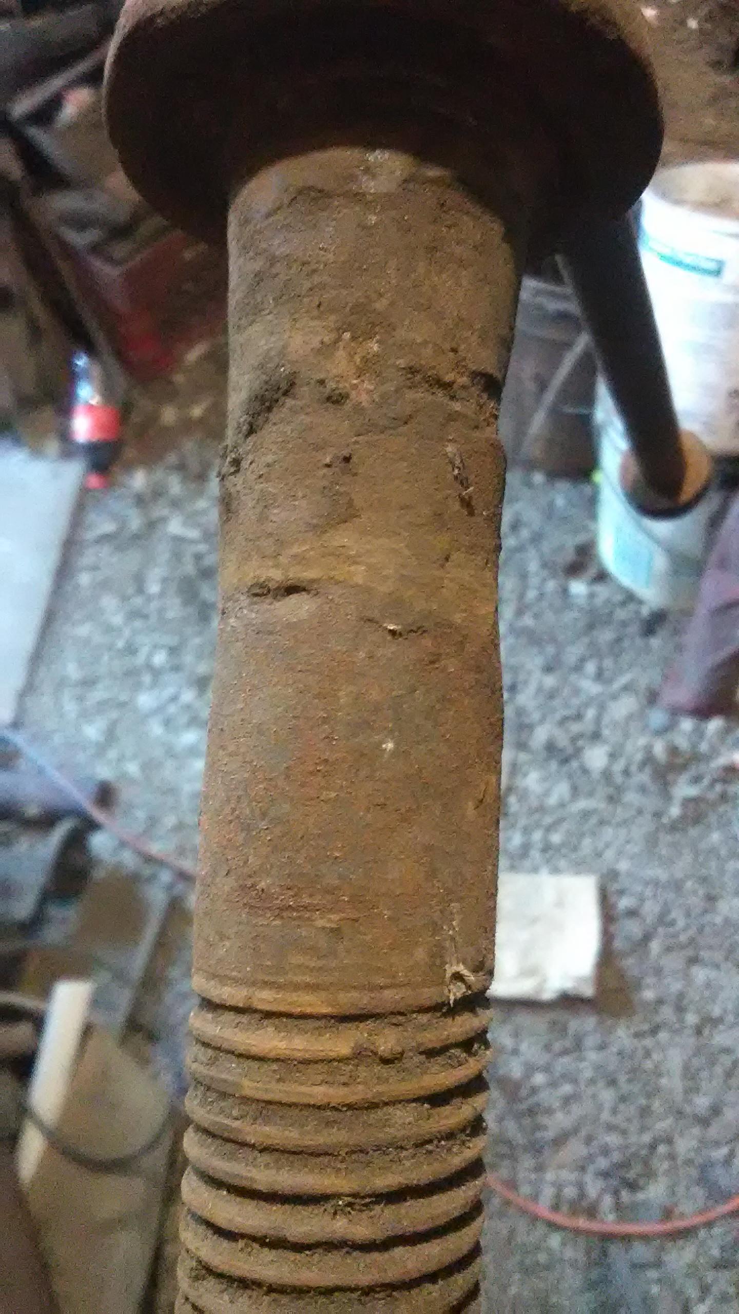
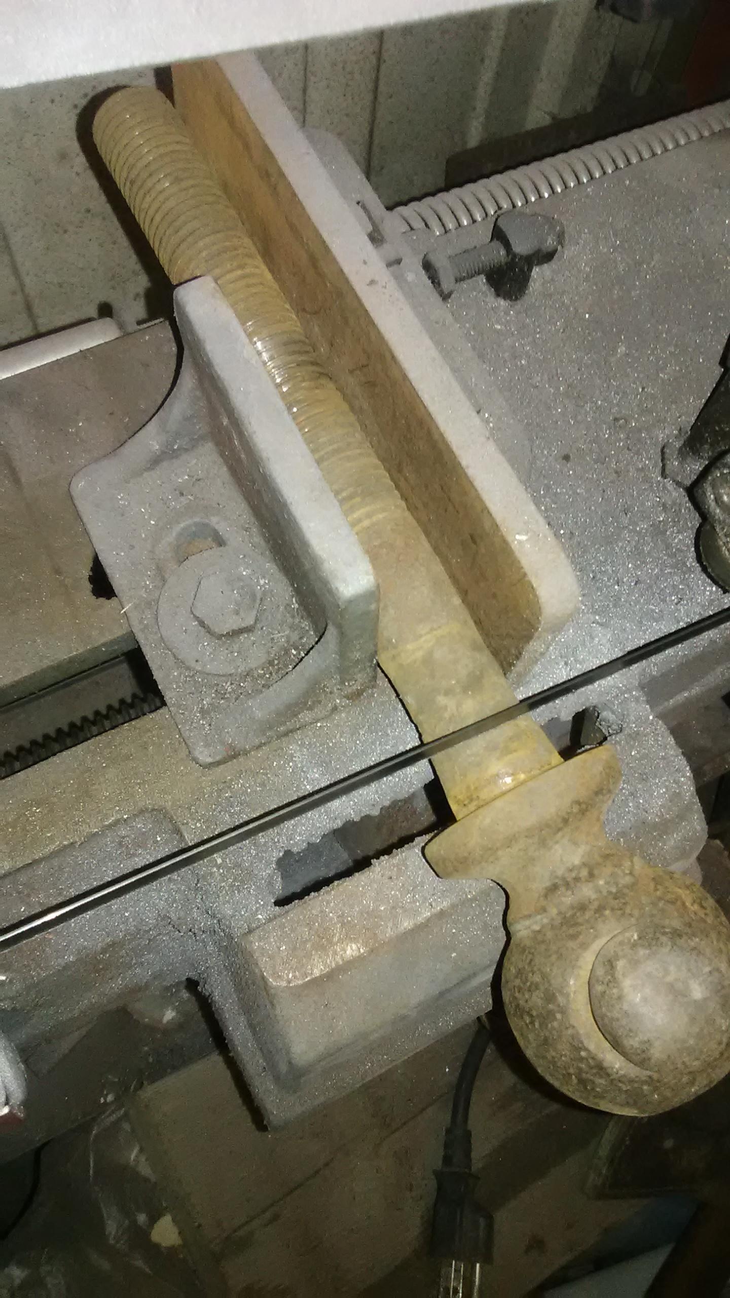
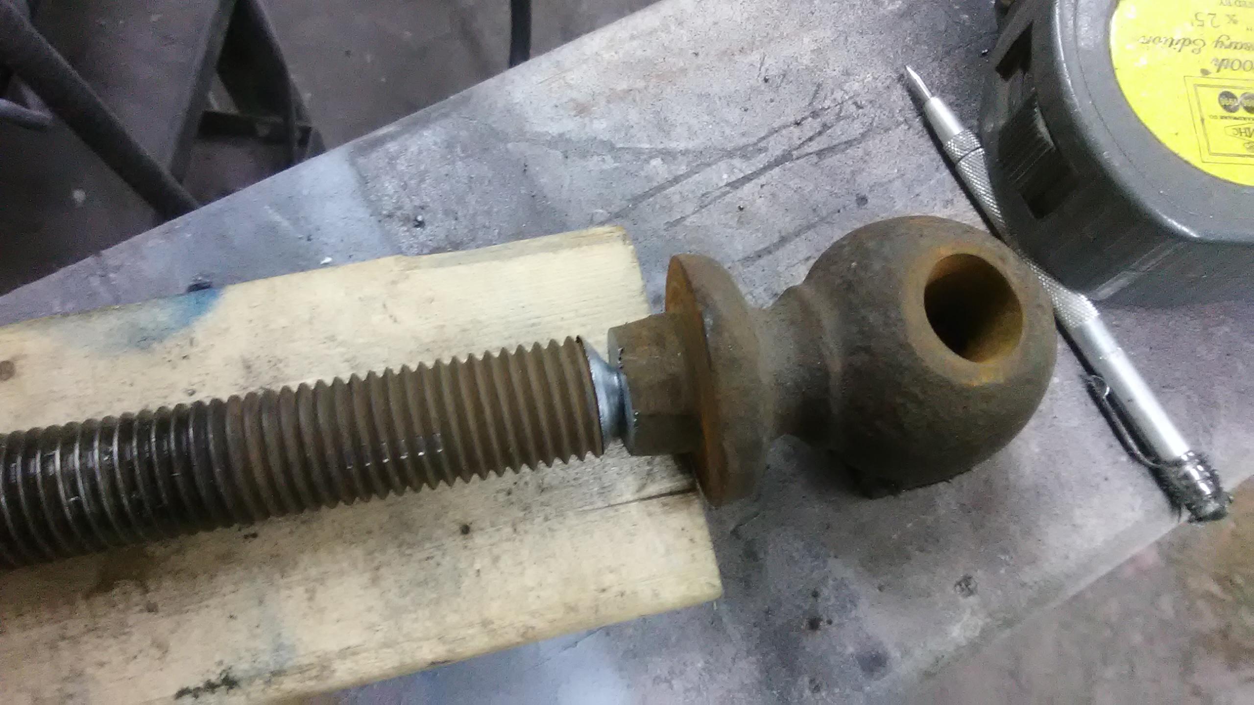
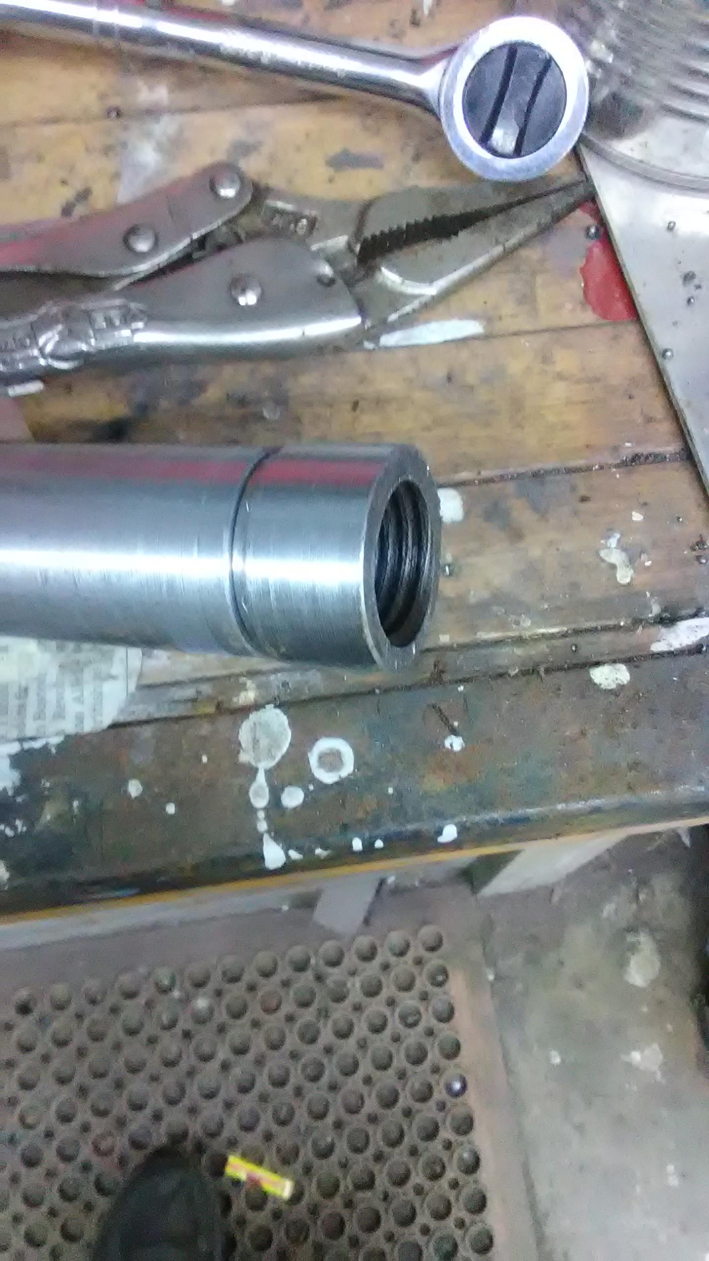
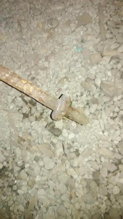
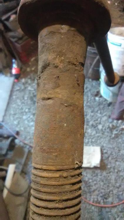
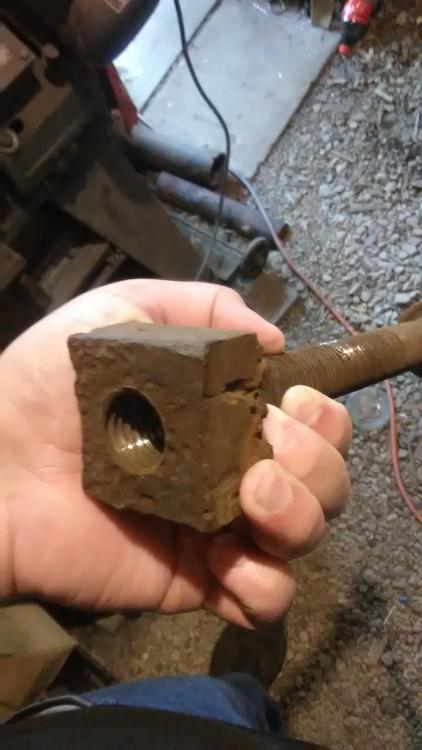
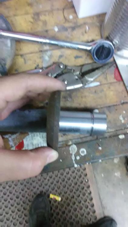
no, the pivot is square bolt but its not as old as the rest, and yes the leg hole has definitely been punched and drifted to a taper approximately .5 inches square and wider on the "back". As for the thread, thats exactly how i intend to make the female thread later when i go over this properly (after finding/making the male thread first of course) as well as a more accurate thread box. right now its more of a "get by". after getting things in a workable state i am going to throw it in my electrolysis barrel for derusting to see more of the details as well. Something else that makes me wonder about its age other than the mounting system is the way the ring is pretty obviously welded around the foot.
-
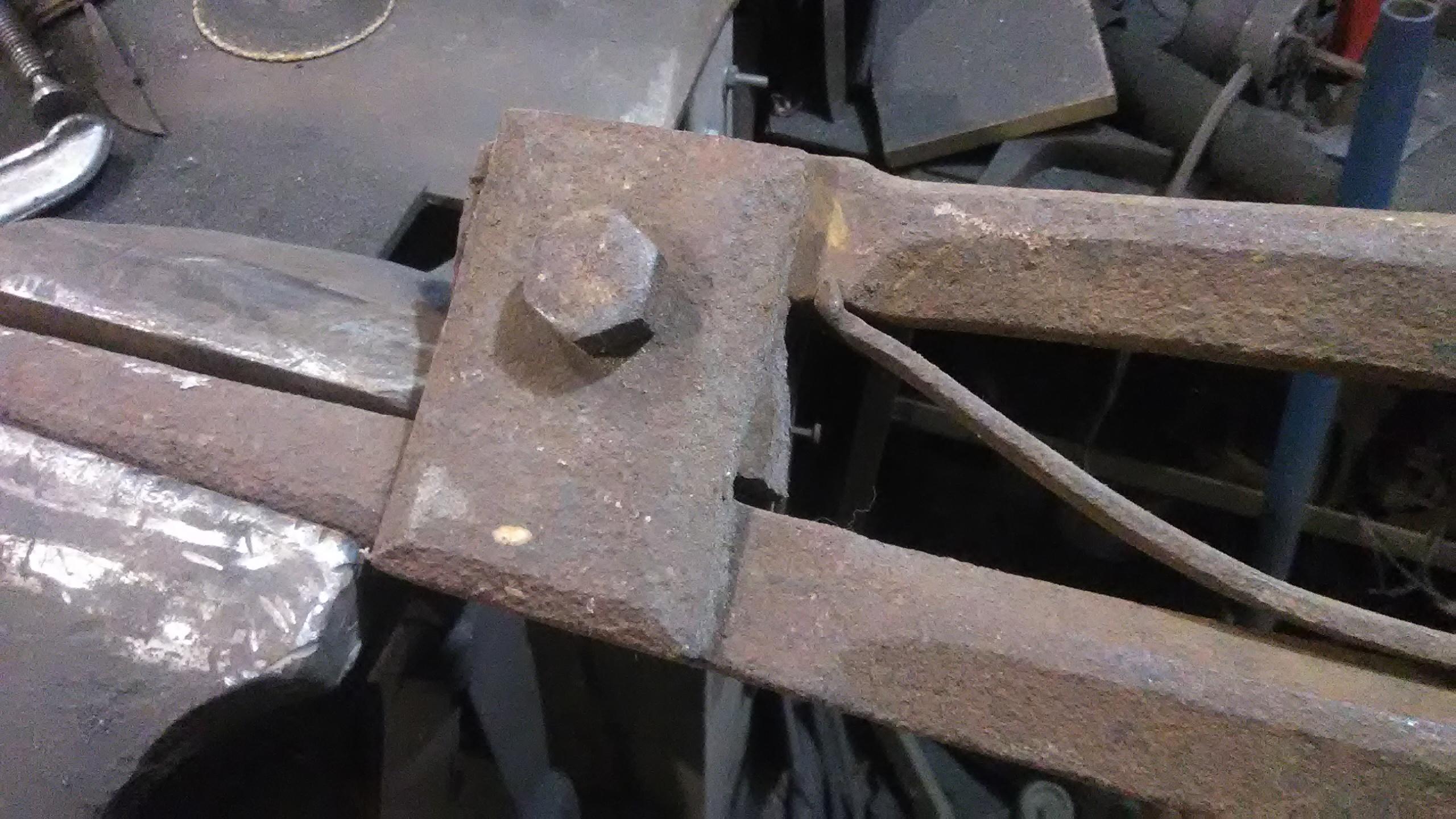
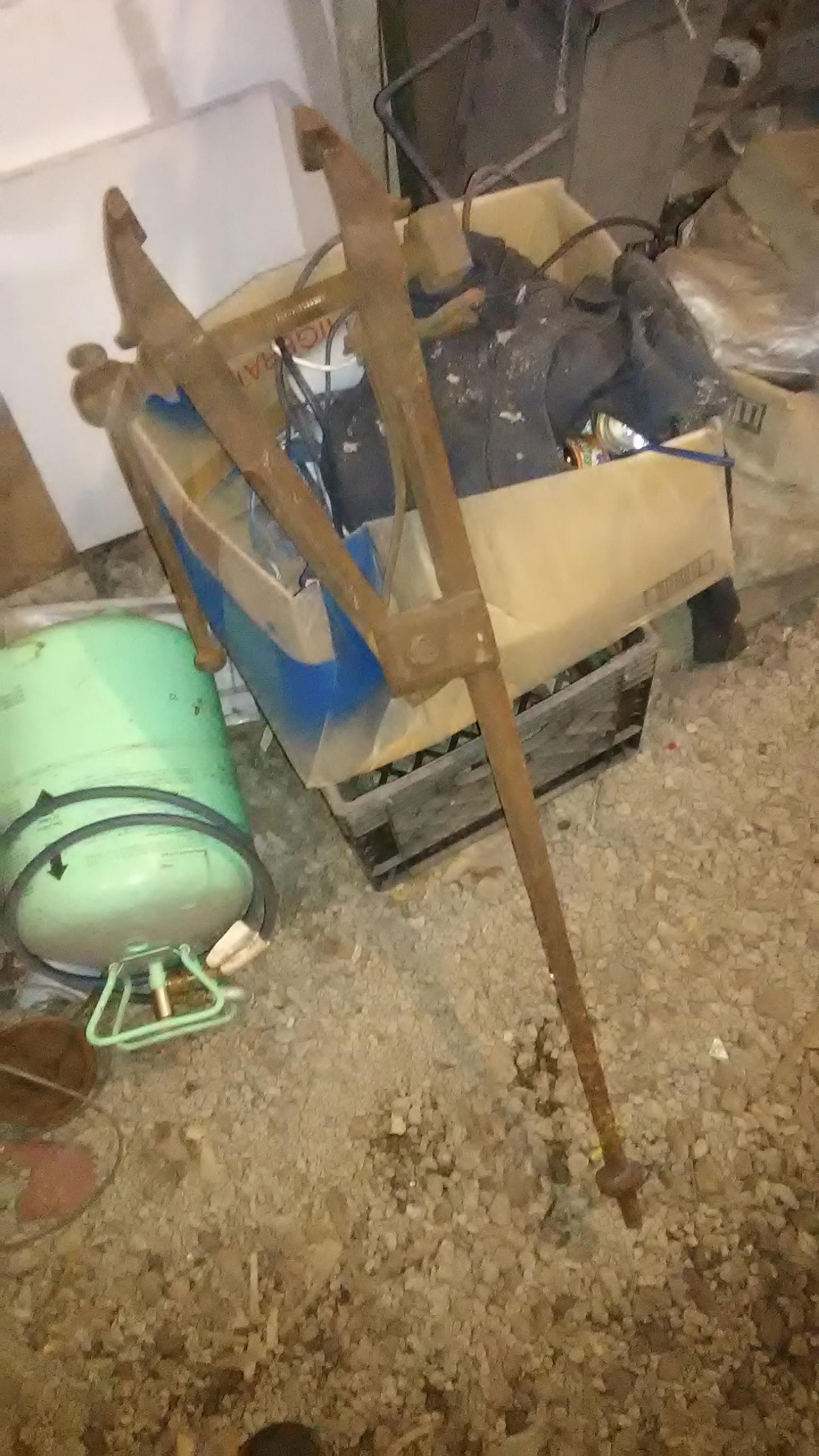
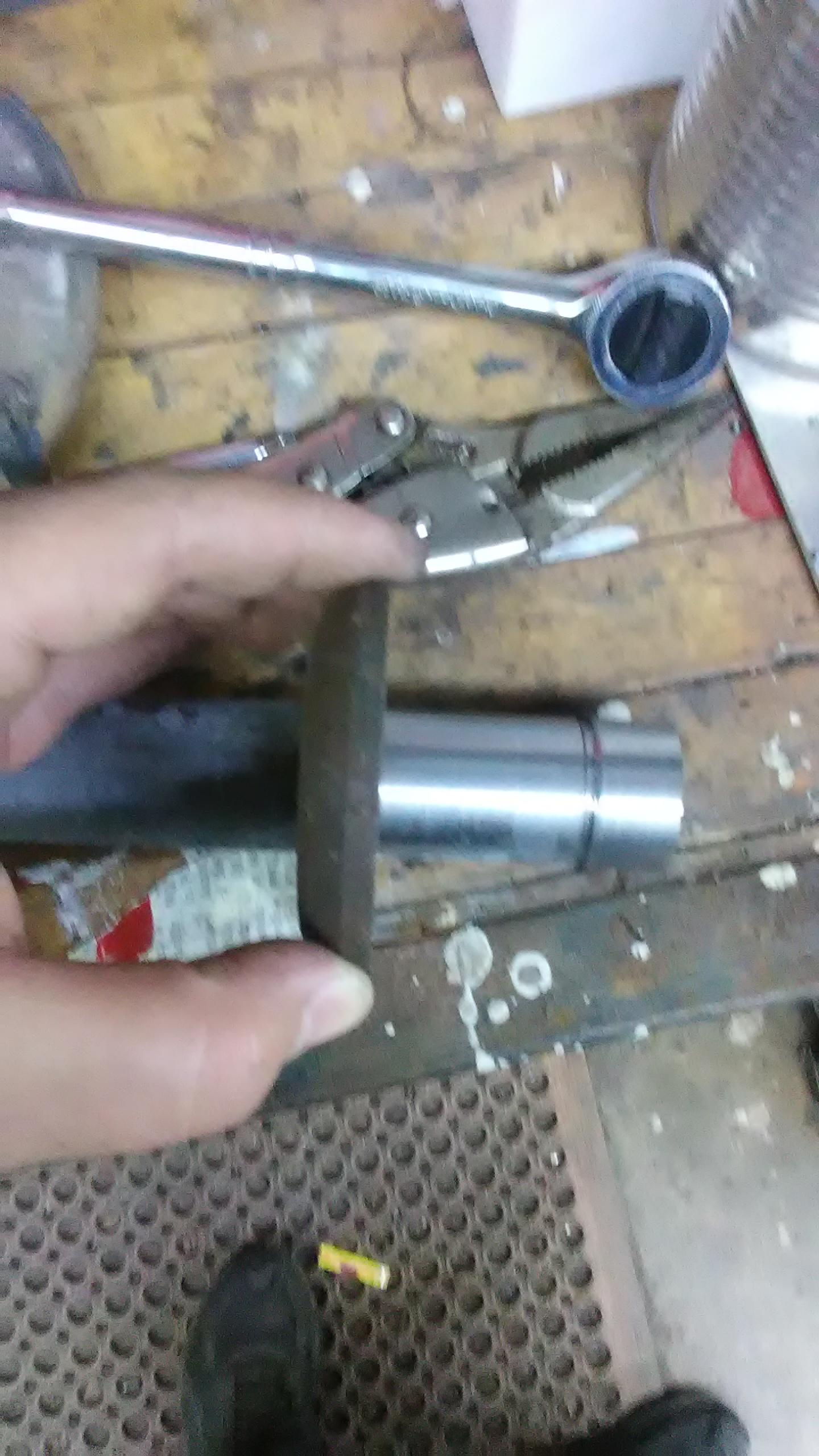
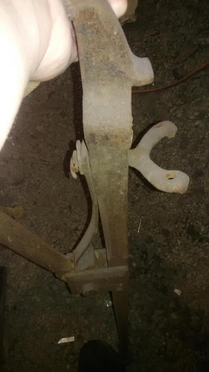
found this at a yard sale for about 10 bucks, and it has set in the corner for a few years now so i figured itd be as good of a time as any to give it a once over. the screw is the most obvious problem. someone has "repaired " it in the past by lopping it off and welding on a 1" bolt in its place and discarding the thread box in lieu of a torche cut square nut. I currently dont have an adequate replacement piece of acme thread and dont really feel like making a square thread on the lathe right now, so i decided to keep the bolt because its a small light duty vise. Another thing showing its light purpose is the way the mounting bracket is attached. it appears that it was a tapered square with threads at the very end but i dont know if that is original as it all seems very light. But regardless i will replace the cludged in bent nail with an extension and a slot for a wedge but will likely replace the whole shebang with a more substantial bracket later. i also will leave provisions for replacing the screw and box later. Now onto the progress pics!


-
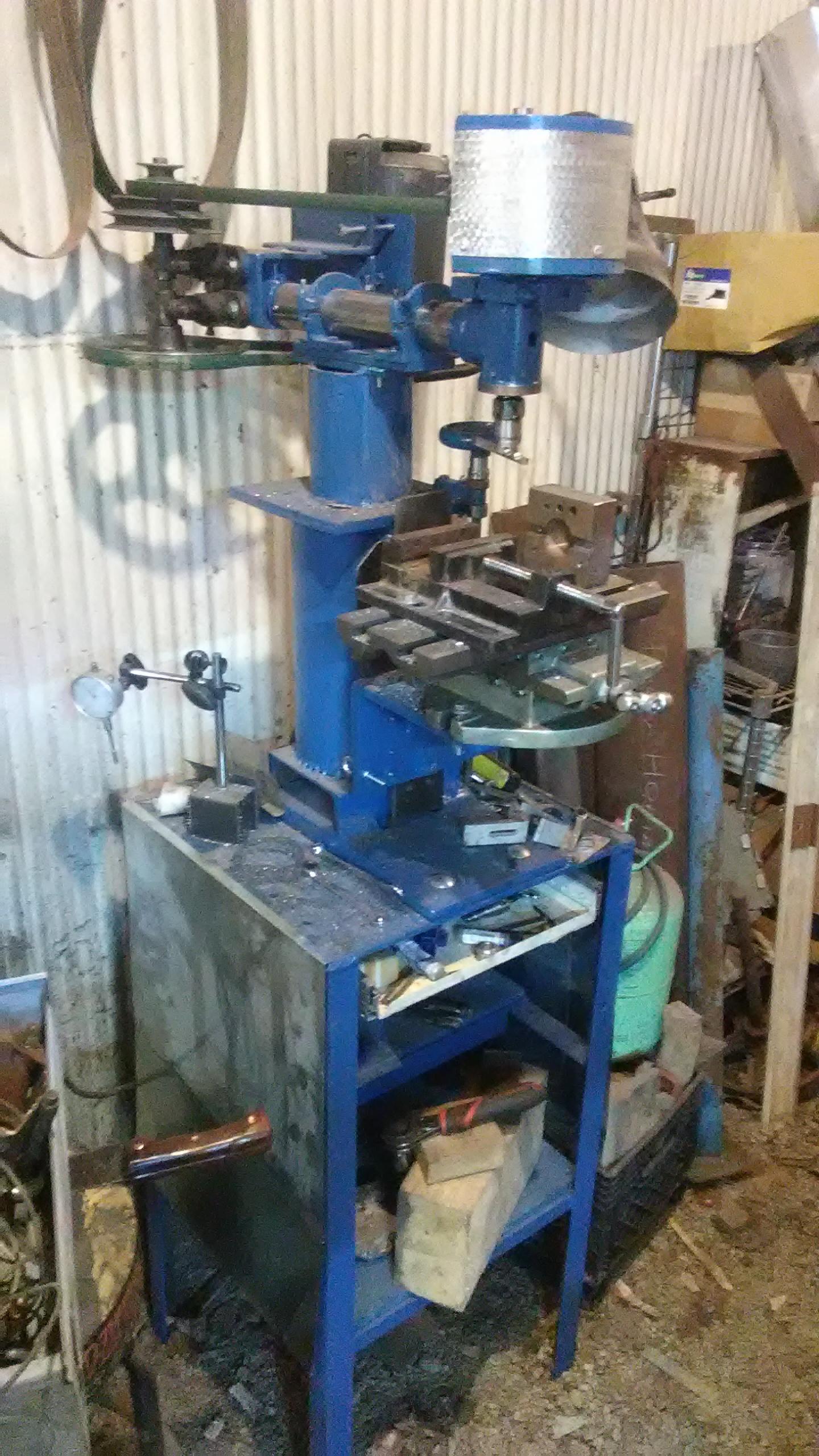
finally got this finished, added a cheap x/y table till i can make a better version, belt guard, paint, z axis, and built a cabinet with the surface plate in the top pull out drawer, plus everything else as far as basic accessories go. I know this isnt really a machining heavy forum but someone may find interest in seeing how a blacksmith builds a milling machine! final product with pretty much finished cabinet


-
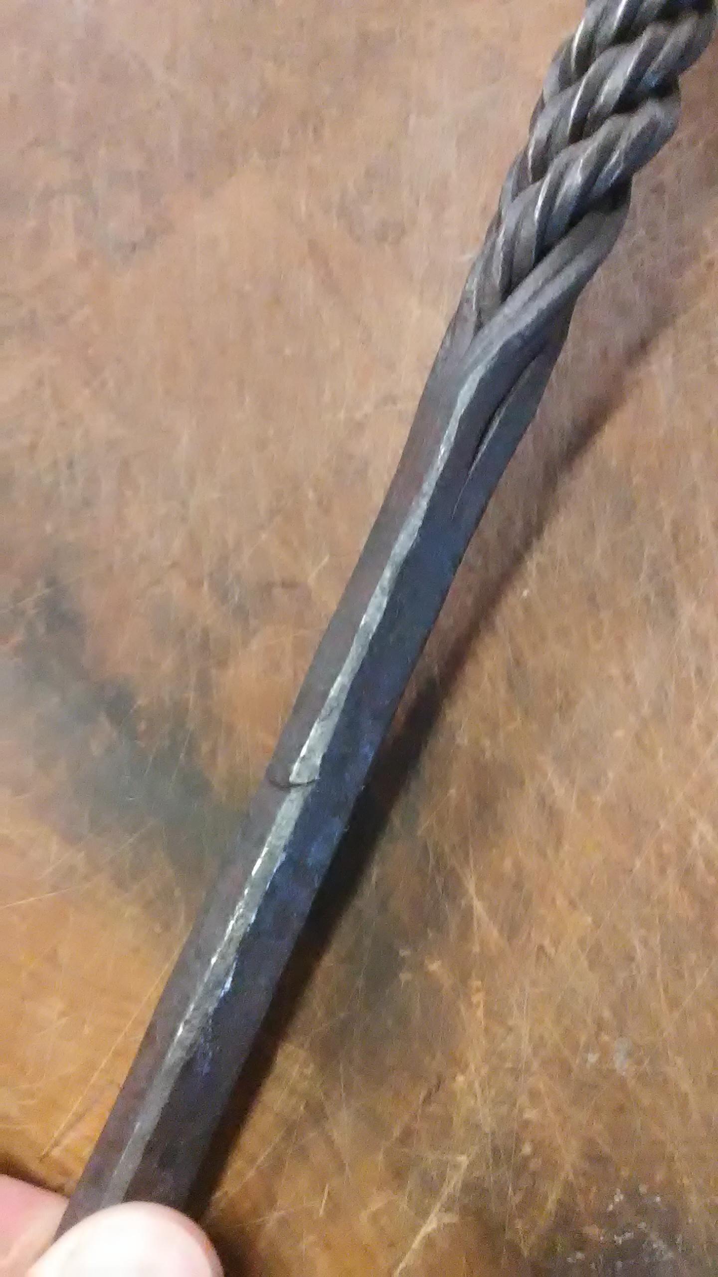
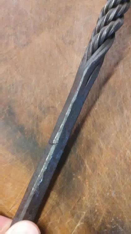
Yes that's exactly correct, and by "the middle 6" " i mean to twist all but one inch of each end of the starting rods, leaving the ends straight for welding together
-
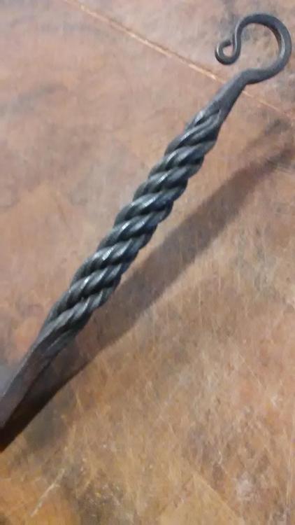
Might as well toss this in here. Its 4 bars of 1/4" square about 8" long, incised on all four sides, twisted in the middle 6", then forge welded for the last inch on each end, then twisted AGAIN (opposite direction as the individual bars) then scarfed and welded to the rest of the piece (in this case a fire shovel) Hope that makes sense!
-
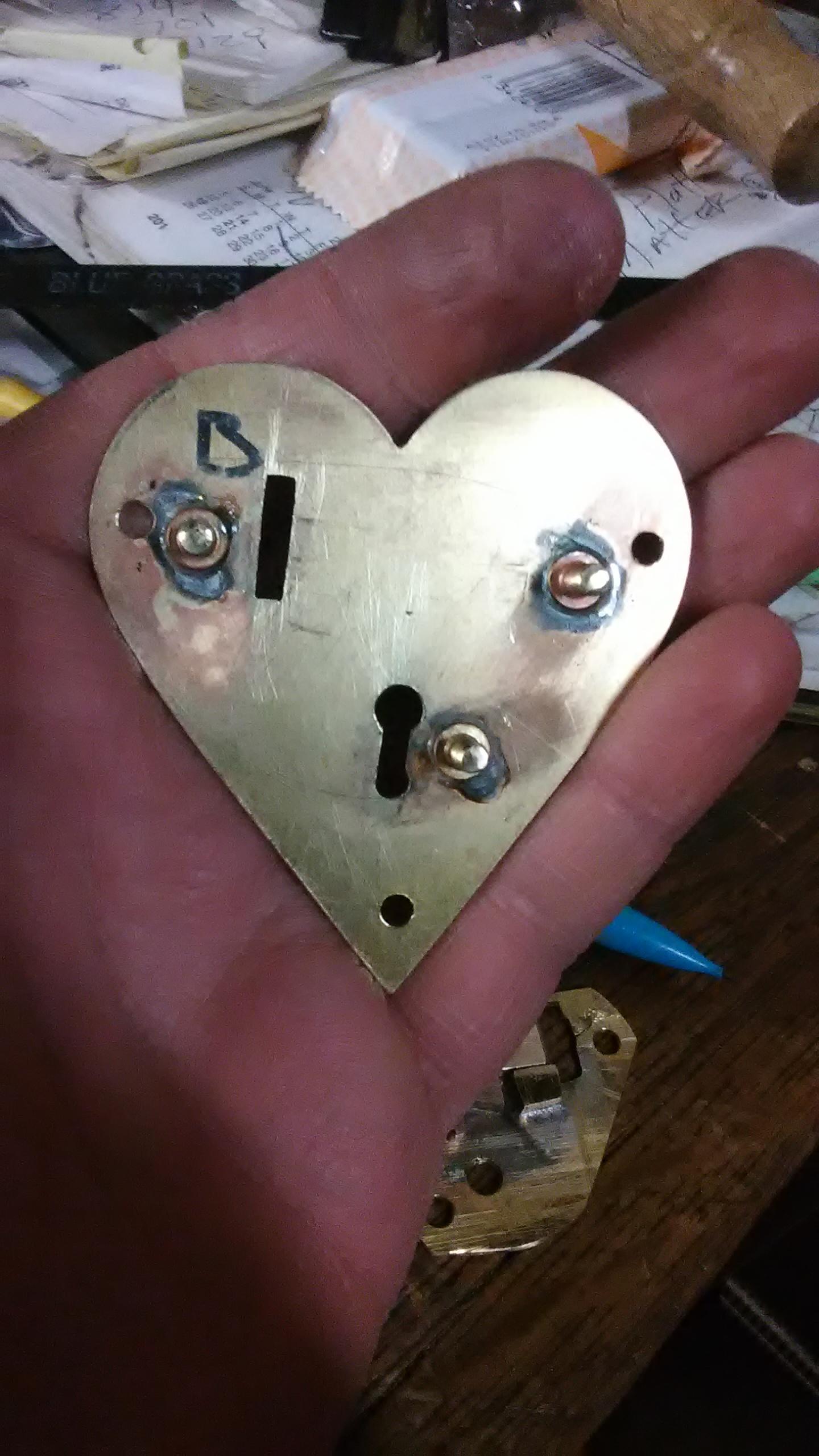
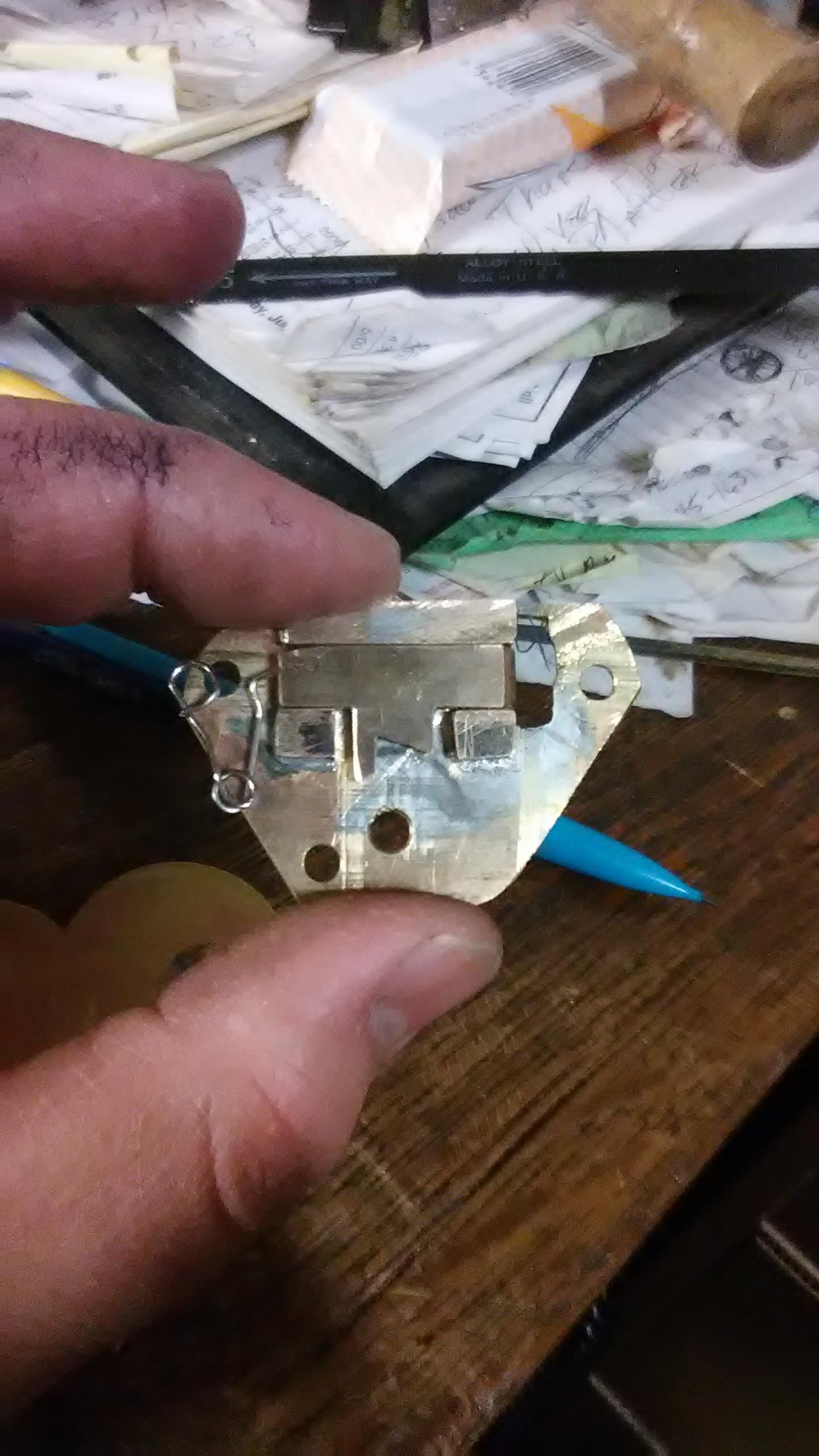
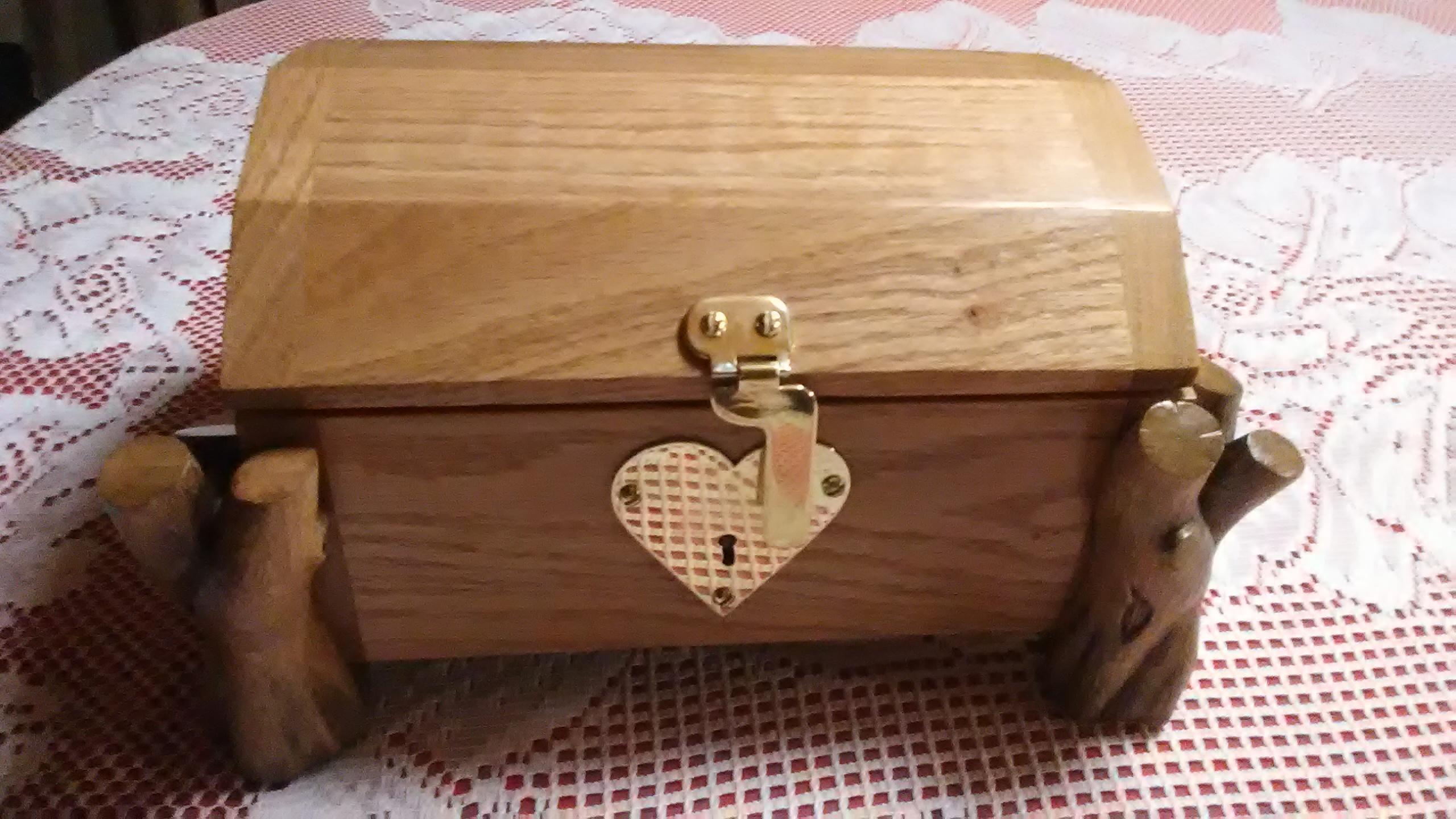
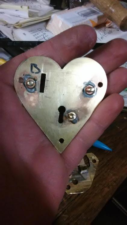
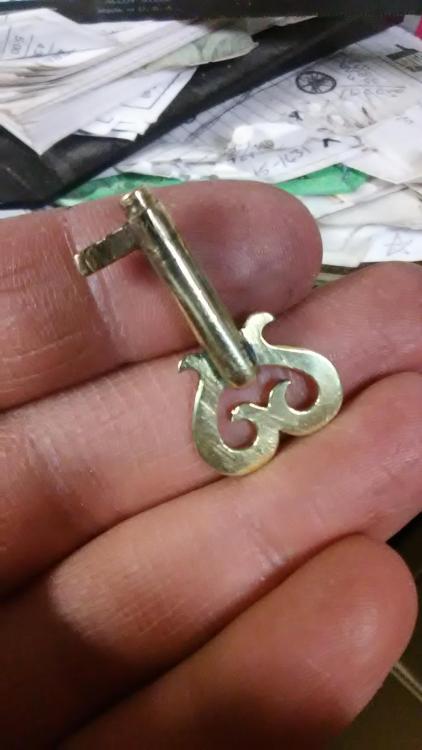
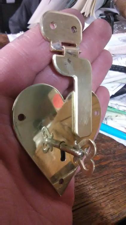
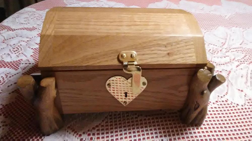
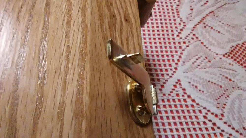
My dad made my sister an oak jewelry box last Christmas and needed a latch/lock for it, so i made this one from brass plate and bar stock.

-
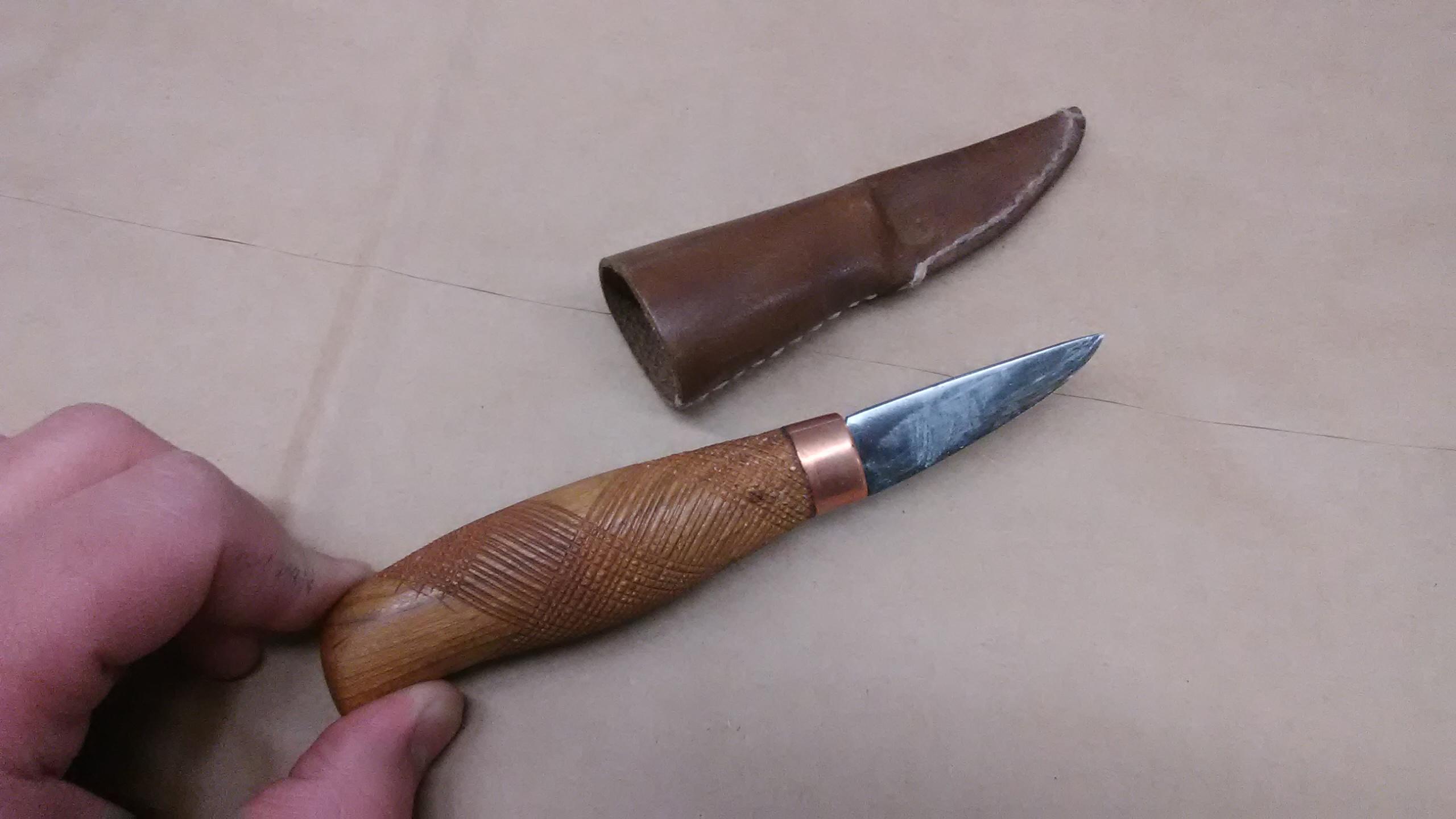
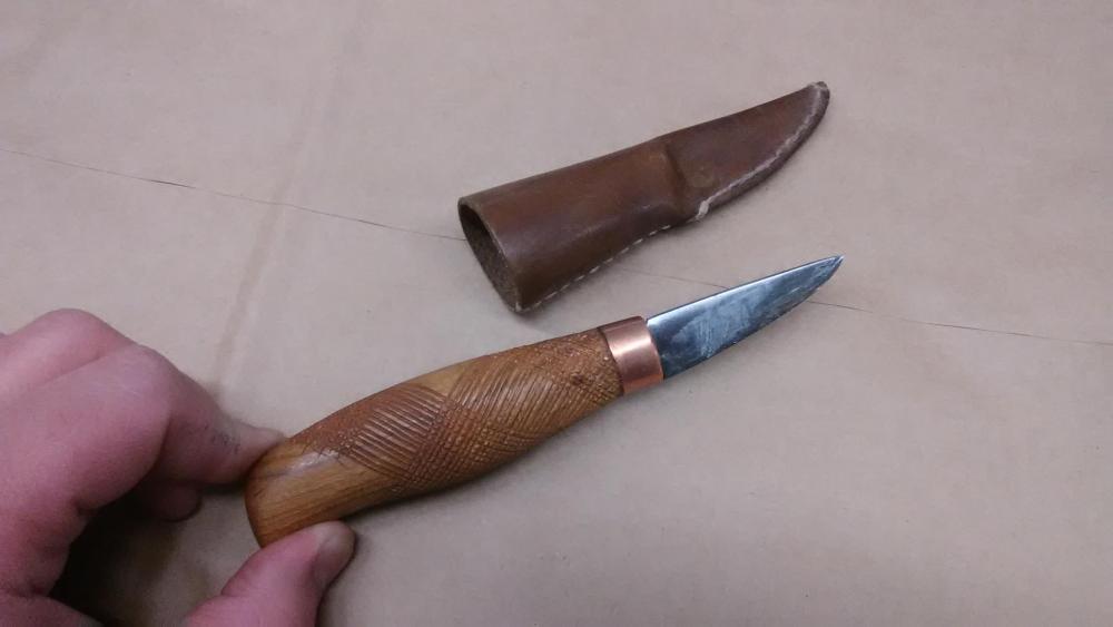
1085 for the blade, which is about 1 1/2" long or so, handle is cherry wood about 4" long and is my first forray into checkering. Which turned out great but i learned a whole lot of things to NOT do, so the next one will be better. It's all finished with a copper ferrule and a simple leather sheath. Its hands down my favorite carving knife to date.
-
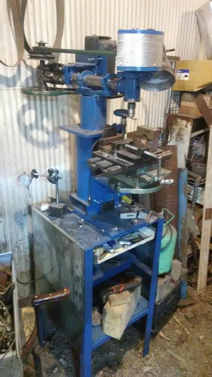
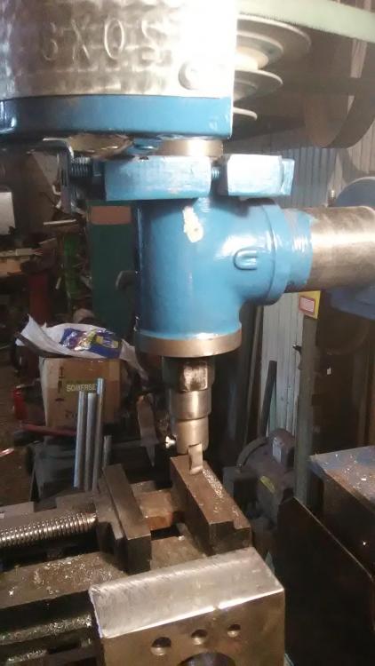
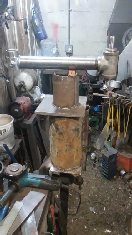
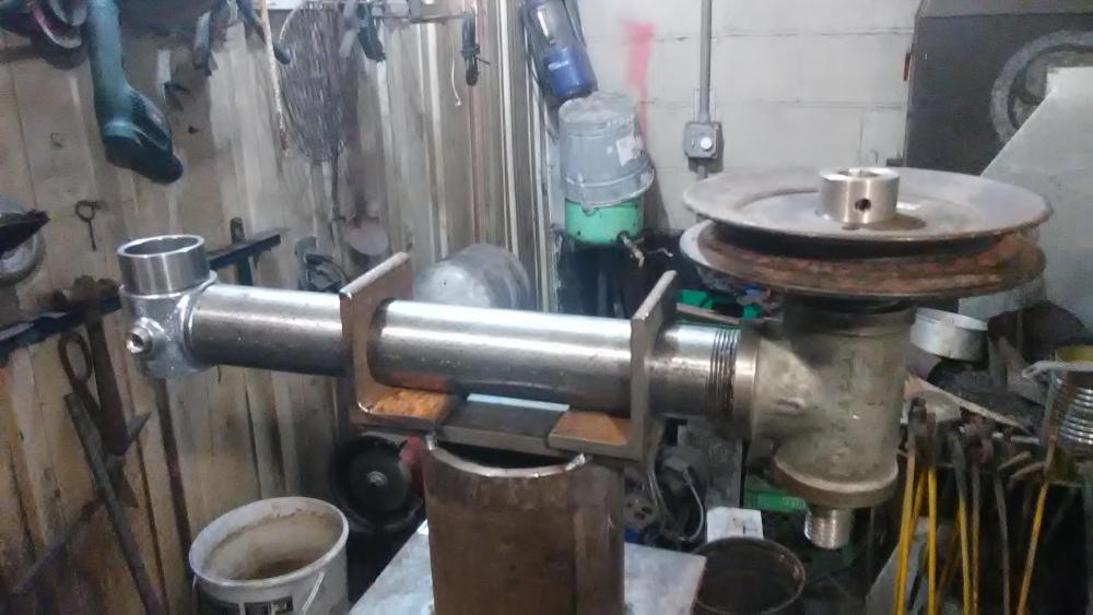
The title says it all, had this project in the works for a while now and it's finally gotten to the point that it looks like something so i figured now it's the time to post some pics and details. It's built pretty much entirely from scrap, save for fasteners. The column is 8" well casing, capped with an 8" square of 1/2" plate, then the head is blocked 6" higher for the head mount on 4" pipe. The head itself is a 1 1/4" pipe with a heavily machined T on the end for the spindle. The spindle is mounted in tapered roller bearings, threaded at the nose 1" x 10 tpi for fittings like boring heads and fly cutters. More details to follow. The drive is going to be 4 step step pulley primary reduction, then a 2" to 6" final reduction to the spindle, which should make the bottom end speed with the 1725 rpm motor, about 200 rpm. The angle iron brackets that hold the head are bored to fit the horizontal pipe. They'll be split and fasteners added to clamp the head (it'll look like main bearing caps). Then the angle of the head can be turned left or right and clamped if needed. When the drive and the head is complete I'll add guards over the spindle pulley then it's on to the slide ways!
-
on an earlier post i had shown my home built small helve hammer, ( ) I was going to ask if anyone had experience with tuning leaf spring helve hammers and if perhaps there were any links to information on the subject. ive been having a world of trouble replying to said post but i figured this was a good subject to start a new post about anyway. Ive searched here and elsewhere and came across something about tuning light sheetmetal forming helves but it was pretty sparce on details. The hammer is striking fairly well with the treadle half depressed but it seems to miss a beat when all the way down, and i feel like a hammer with a 15+ pound head should be striking much harder than it is.I can do as much work with a 3# hand hammer at the moment... Any help is greatly appreciated and sorry in advance if im not able to respond to this post, the site doesnt seem to want to let me post replies for some reason
-
Also it appears that i accidentally posted that in the account i made when i thought i lost my account name ages ago... back when i didnt know how to work a computer. i guess this computer saved the login info and i never told it otherwise! so long story short, this is my post, sorry about that
-
Yes that'd be a good place for this type of transition, it leaves just a tiny bit of extra metal to a place that really needs it. the only issue (if you can call it an issue that is) is that its one-sided, that is it leaves a front and a back side, or a presentation face and a back face. that's one of the reasons i left the back as forged. one thing i learned about whitesmithing on this project is that you need to leave it a tad thicker than you think you need too to allow for filing, like a knife. And an added benefit of having a "good" and "bad" side is that when there was a bit of a deep mark in the good face, it could be flipped and hammered colf from the back in that spot to bring it up and make the whole surface a bit more even
-
Well it looks like I've got quite a few books to find and add to my collection! I've actually looked through the book on the sorber collection, actually that's where i saw many of the examples i mentioned before. mtmetal, that's pretty fantastic work! and very faithful to the originals to boot. I've wondered what the flame height/etc. was supposed to look like in practice. I never even gave a thought that The "candle socket" on the rushlight might actually be a snuffer, though it does make quite a bit of sense, it'd be a bad idea in a finished home to go blowing melted grease and ash around when its time to put out the light afterall. One of the intriguing things about grease/oil lamps is that their fuel isn't by itself flammable (unlike the aforementioned cornchips!) And without a wick its pretty safe, albeit messy, in the case of it being dropped or tipped over. F. Turley: I've actually seen one of those forms in a swage block before, something said it was for making ladles, but it was actually a lamp form. The point was far deeper and longer than would be practical for a ladle mould. Had i known about those type of lamps years ago, id have carved such a depression into my swageblock form before i had it cast! Itd simplify both crussie making and making lead ladles as well! Thanks everyone for the amazing wealth of information on the subject, I've learned more from this post than i have from untold amounts of time searching the web.
-
wow! thank you for that information, for some reason i always thought there was more too it than that! Might have to try my hand at making a couple to make those rush holders in the corner seem like they're actually going to be put to use! Rushlights are pretty interesting, hardly anyone knows about them as classical lighting implements these days. everyone thinks all they had were candles but really rushlights and oil lamps were surely quite a bit more common. I've actually noticed that most rushlights have a provision on the moving arm for holding a candle. Though many I've seen have also had just a welded ball as weight.
-
Hwoolridge i actually have that book (only book i ever spent.over a hundred bucks on actually!) And i use it as a go-to for hinges, latches, and the like but there's hardly any household items beyond door/structure hardware. Thomas, that's the kind of thing I'm looking for! Thanks for the suggestion, i need to hit the library or just order it if i can Charles ill definitely keep that in mind, the internet can be a difficult place to navigate and i definitely need all the advice i can get to make it a bit easier! Thanks for the link John there's some awesome stuff there Frosty, yeah the basic lamp is extremely old and so far as I've seen there's dozens of different forms in every culture. i remember seeing ones made of pottery at some point which were smaller than i expected but short of that I've never seen one in person. betty lamps as i understand are an improved design over the previous form. the simple oil lamp was like a lead ladle with a small point that held the wick and a basin for the fuel whereas the betty lamp had a small strip of metal under the wick that heated the oil a bit more effectively as well as a hinged cover to keep the oil from splashing around so much. Actually i believe "betty"is a corruption of the german word "besse" meaning better. That's about the extent of my knowledge on the subject though at the moment. And I'm glad i could stimulate some ideas!