Ed Steinkirchner
-
Posts
344 -
Joined
-
Last visited
Content Type
Profiles
Forums
Articles
Gallery
Downloads
Events
Everything posted by Ed Steinkirchner
-
integral belt hatchet
Ed Steinkirchner replied to Ed Steinkirchner's topic in Axes, Hatchets, Hawks, Choppers, etc
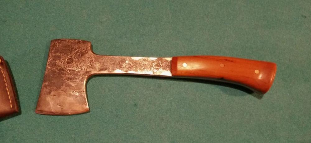
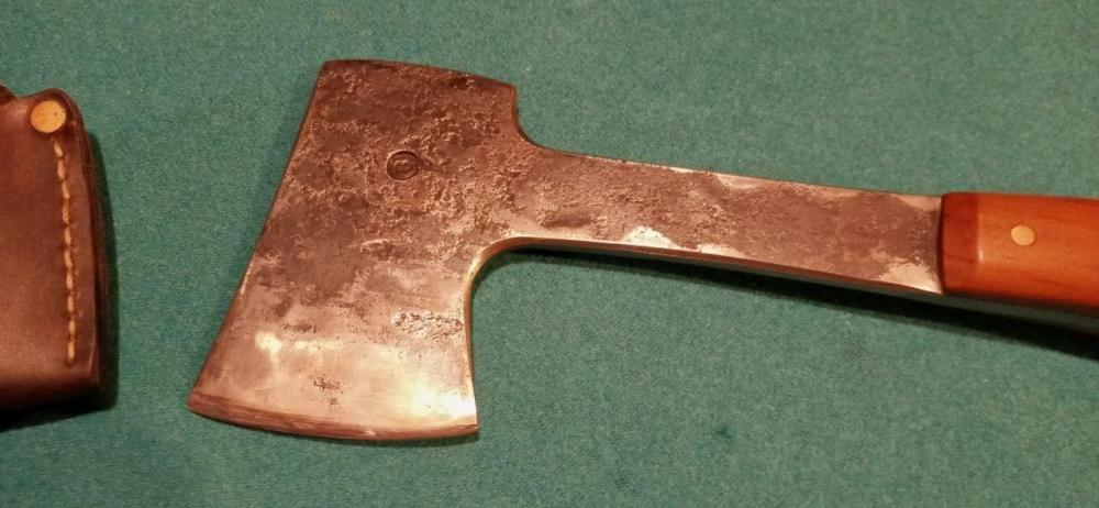
George you nailed it's proposed usage actually! It went to my brother for using when hunting, specifically for splitting the pelvis on deer and small tasks around the hunting camp like kindling. It's tempered for that purpose as well to keep the edge from chipping when biting into bone, which is how our father ruined his favorite knife a few years ago. -
integral belt hatchet
Ed Steinkirchner replied to Ed Steinkirchner's topic in Axes, Hatchets, Hawks, Choppers, etc
Not sure on the weight Frosty, it's similar to a moderately sized Bowie, but the forward balance makes it feel like a heavy knife. On the flip side it makes for a light and thin axe which is pretty comfortable for light wood shaping, kindling splitting, or dressing larger game. As for the "patina" it's just forge finished, then the profile draw filed with a fine single cut file, edges broken, the edge ground and polished, then the whole thing wire wheeled then gone over with a coarse black polishing compound on a spiral sewn wheel to give a nice sheen and soft feel. -
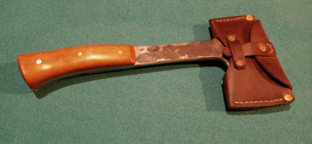
is integral the right name? not sure but its made like a full tang knife! anyway, made from 5160 (leaf spring) and all one piece, measuring about 14" overall, 5'' handle, and a head about 3.5'' wide. It averages 1/4'' thick, but the head tapers to the edge and the tang under the cherry bwood scales is tapered in thickness as well. overall was very fun to make and feels very nice to hold
-
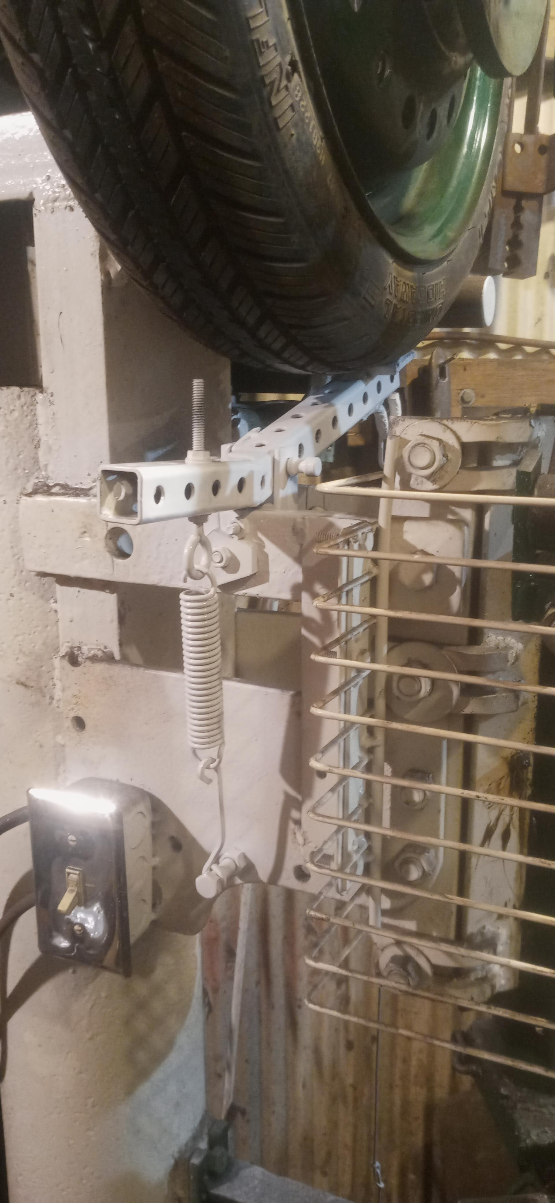
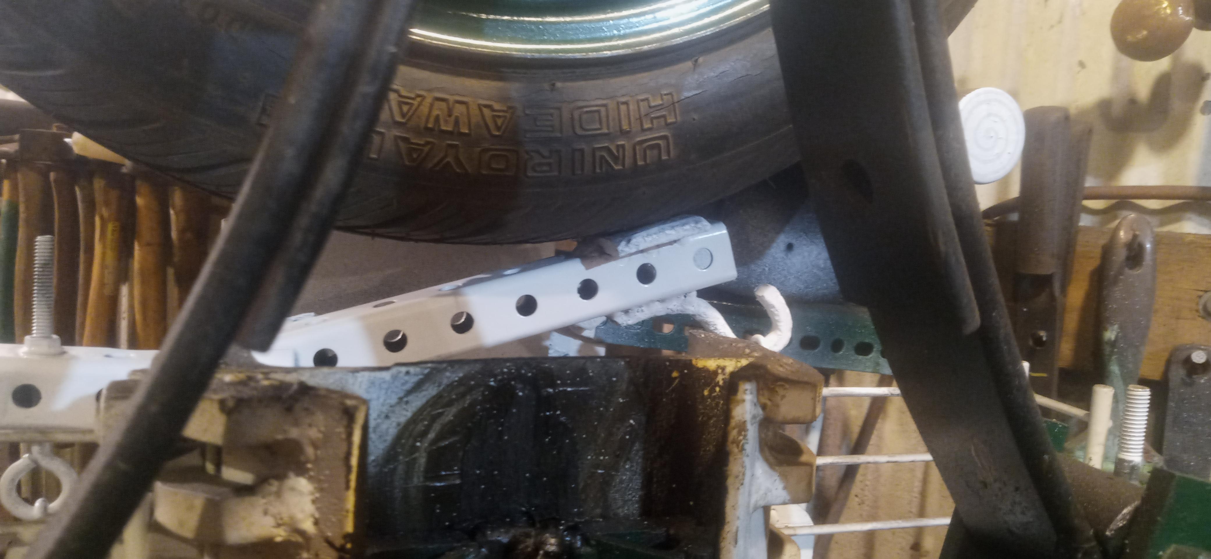
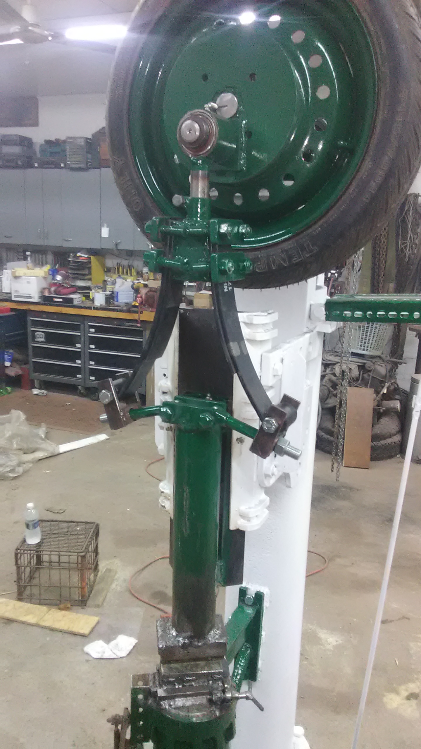
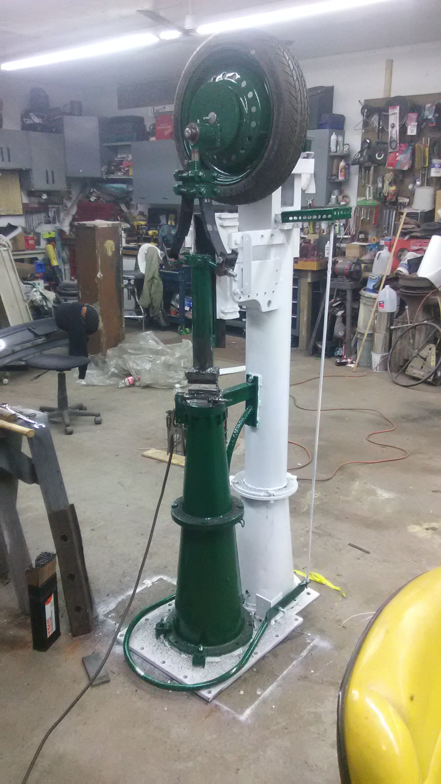
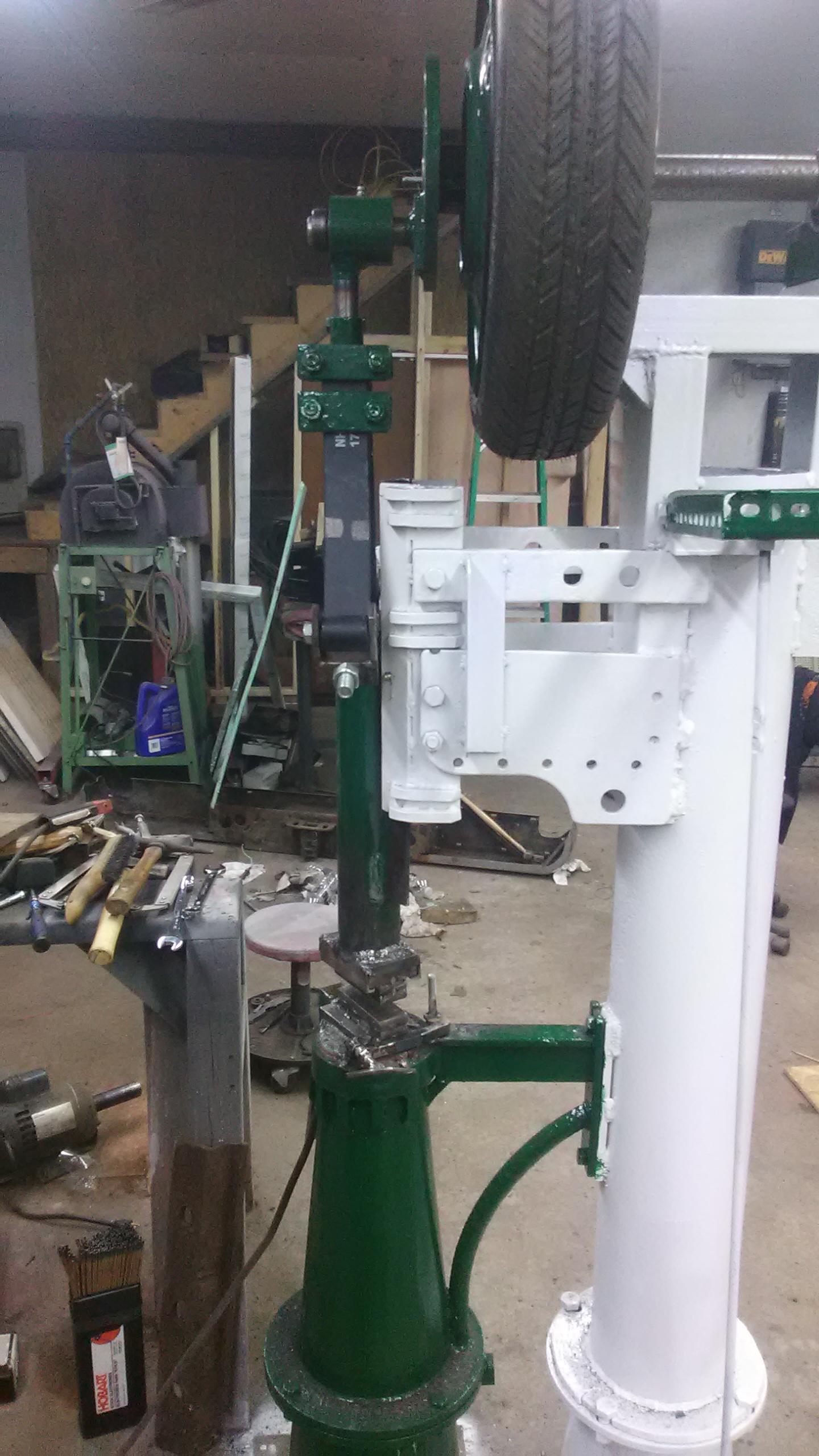
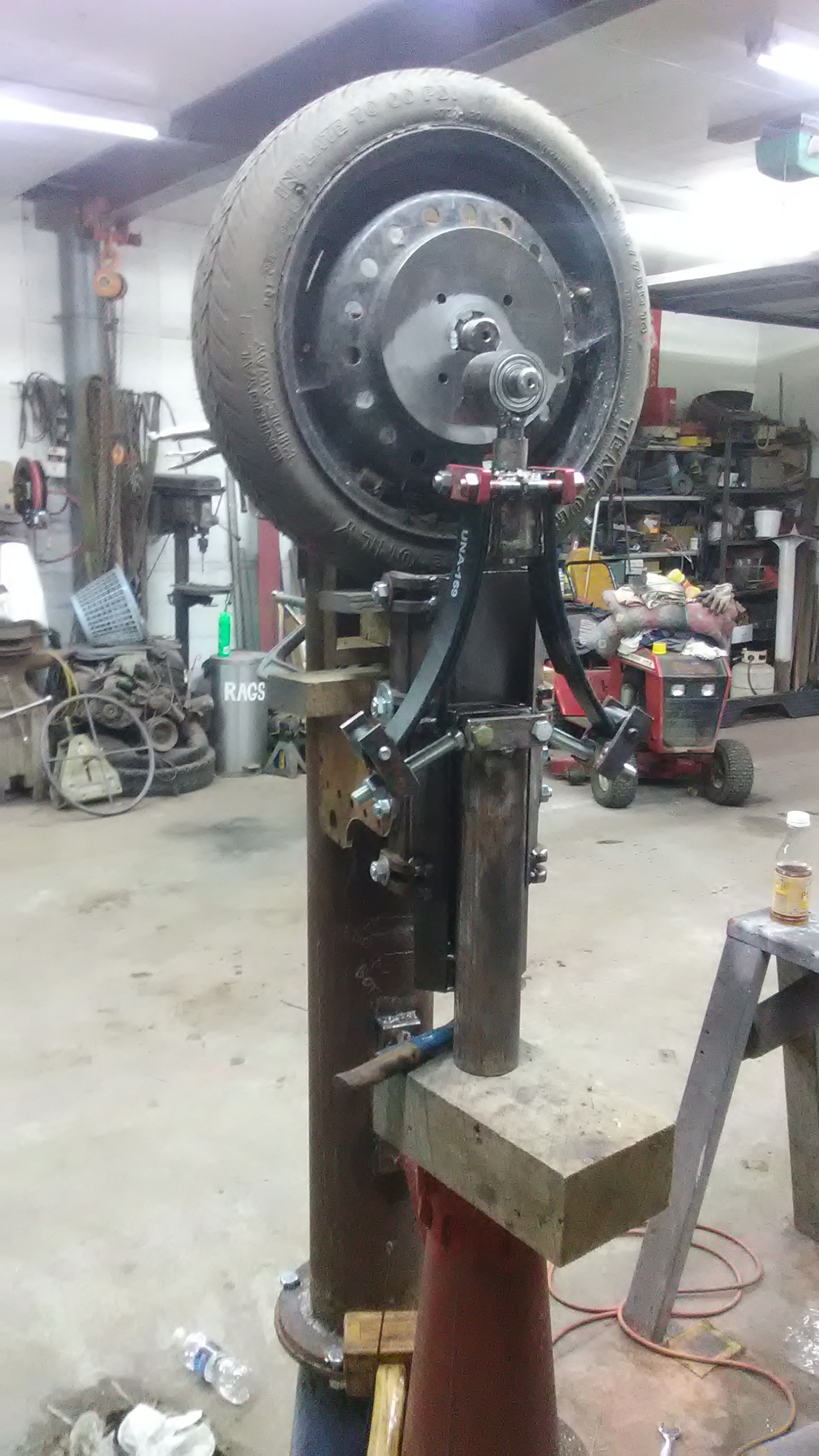
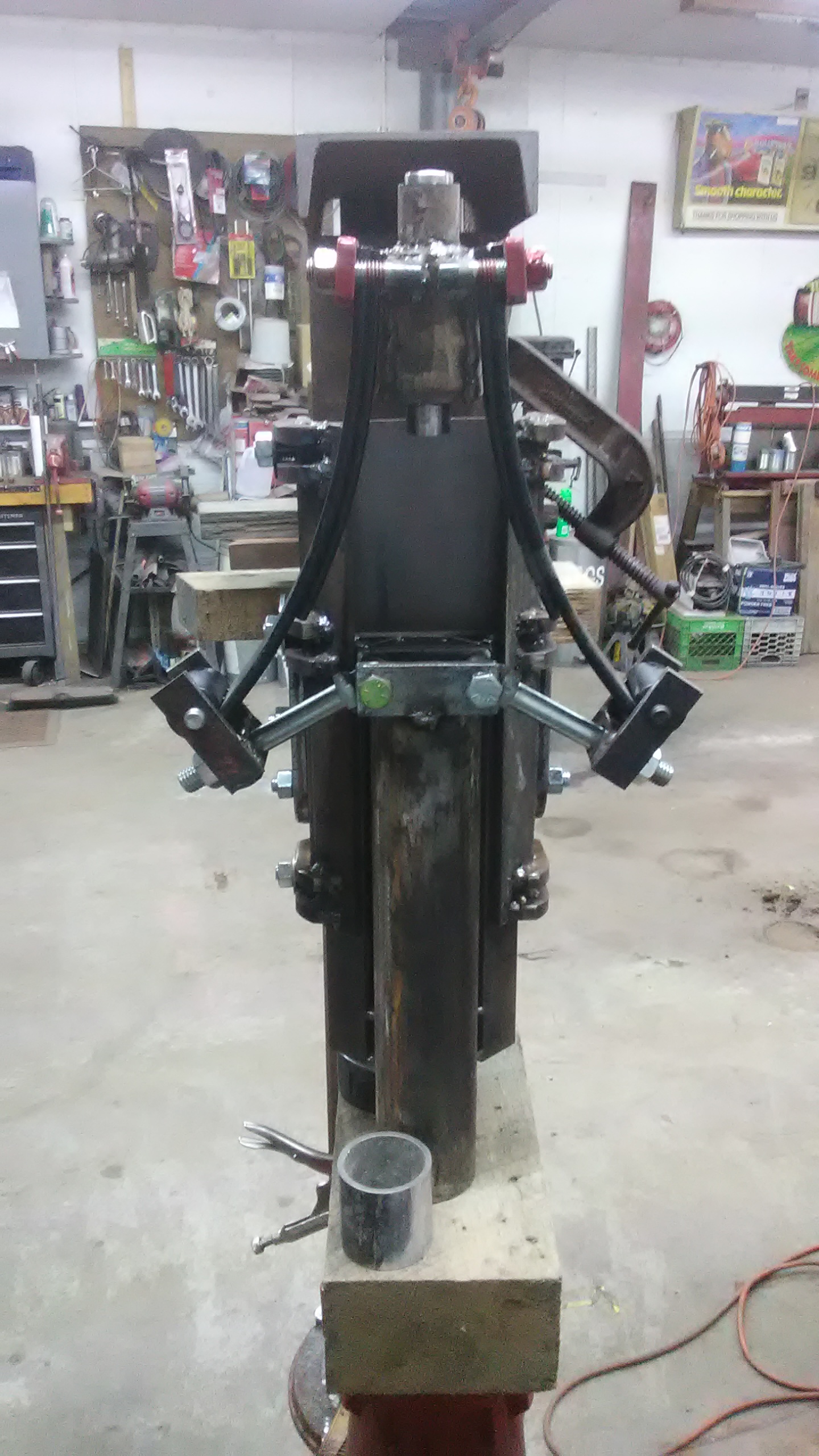
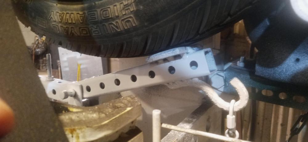
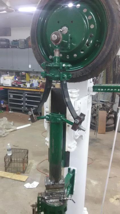
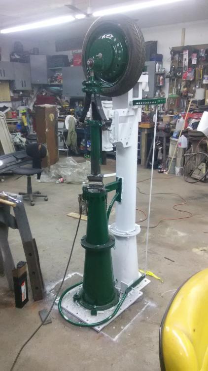
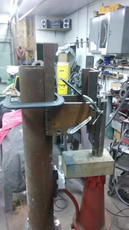
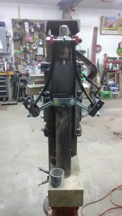
After a couple years of use, I broke down and added a brake to the power hammer. It was just too much of a pain to feather the treadle to get the dies open and line up tooling before letting the tup drop. Construction is pretty self explanatory by the pics but some basic details: It's a seesaw type where the spring tension is adjustable to tune how grippy the brake is against the tire. The brake pad itself is a 3" square of smooth steel welded to the arm and the brake is released by a small rod running to the treadle and can be adjusted with a turnbuckle. And just for clarity's sake, the motor is applied to the wheel with a push rod linkage and the brake is removed by tension, I went with a push rod for the motor because any over-pressure flexes the rod instead of overloading the motor's shaft (though that may not have been an issue but it was simple enough to build) As of now this is a prototype and the arm itself will likely be replaced with a better fitting (and better looking) forged one in the future if it works out well, and testing so far is promising! (Also there is a guard in front but it's been removed for clarity)


-
handle for giant iron skillet
Ed Steinkirchner replied to Ed Steinkirchner's topic in Blacksmithing, General Discussion
I don't currently have a pic ATM, but it's the same proportions as a standard Griswold but nearly three feet across! JHCC: I dig that idea, makes me think that maybe the trick would be to just build a spider type stand and handles that just grip when needed and come off otherwise, kind of like lid lifters for dutch ovens or those removable handles for grill skillets -
handle for giant iron skillet
Ed Steinkirchner replied to Ed Steinkirchner's topic in Blacksmithing, General Discussion
Frosty: I think that's exactly what it was, and the misalignment is exactly why it has the variation in rim thickness! As for why it's needed, it's more of a novelty thing to have around and maybe cook with it hanging from the firepit crane potentially, just as more of a showpiece. Although I think with something of that size you could handily cook for around 30 people at a time as it's about the sze of some of the bigger aluminum braziers (har har) that I used when I was a chef at a resort ten years ago so it's not as impractical as some may believe! As for weight, I'm guessing by picking it up that it's in the ballpark of #50 Stash: that's more or less what I had in mind. A cross of bars or perhaps a ring as a cradle with the handles or what have you attached to it instead of the pan -
Looking for a suggestion on putting a handle on a very large cast iron skillet that was cast by a family friend at the foundry here in town about 15-20 years ago. It's around 33" across, and about 3.5" deep with a single small pour spout. However, there are no lugs, handles, holes, or any way whatsoever of mounting a handle/bail/grips. As well the edge is of varying thickness from a strong 5/16" in some places to as thin as 3/16 in others. It's going to be used on an outdoor stove in the pavilion or over a fire ring due to its size so any way of handling would be fine. I'm a bit concerned about opposing handles potentially breaking the rim when it's picked up and even moreso if I hung it from a bail like a kettle, so I was considering just making a frame for it to sit in without bolting/ riveting it in so it could be handled without stressing the cast iron. The cast iron is of unknown alloy btw, it is probably ductile as that's what they were casting at that time but it's possible that it's basic grey iron, so I'm going to assume it's grey. Any advise or experience on the matter would be greatly appreciated Thanks~
-
Friction drive guided helve
Ed Steinkirchner replied to Johnny Woolsey's topic in Power Hammers, Treadle Hammers, Olivers
Details? Very interesting looking at least -
homemade milling machine build
Ed Steinkirchner replied to Ed Steinkirchner's topic in MIlls, Milling machines, etc
I don't have any progress pics of the spindle, but a description should suffice. the spindle is 3/4 inch OD bored through 5/16 for a drawbar to hold the homemade collets. The collets are 1'' major diameter and have a 10 degree taper down to 9/16 for the collet body. this limits my milling cutter shank diameter to right around 7/16 inch in the collets but thats more than reasonable for the light duty work i use it for. My most used endmills are 5/16 solid carbide roughing and finishing (because thats what my friend brings me when the cnc mills at work "wear them out" ) but i also use my flycutter a lot, which is just visible in the above pics and holds a 5/16 HSS toolbit. Im working on upgrading the head to something more rigid now, moving to a 1'' od spindle with a larger bore and larger collets, plus a more rigid fixation for the head to make it less likely to get out of tram. -
Asymmetric wrapped eye
Ed Steinkirchner replied to Donal Harris's topic in Axes, Hatchets, Hawks, Choppers, etc
As I've always understood it, an asymmetric wrapped eye is where the starting bar is bent with just enough material to make the eye and weld to the body. Whereas a symmetric eye is bent in the middle more or less and welded like we'd normally do for something like a tomahawk. I remember a while back someone here doing quite a few axes of the assymetrical welded type, as well as welded langettes and all those tricky welds I'd have to go digging for the posts -
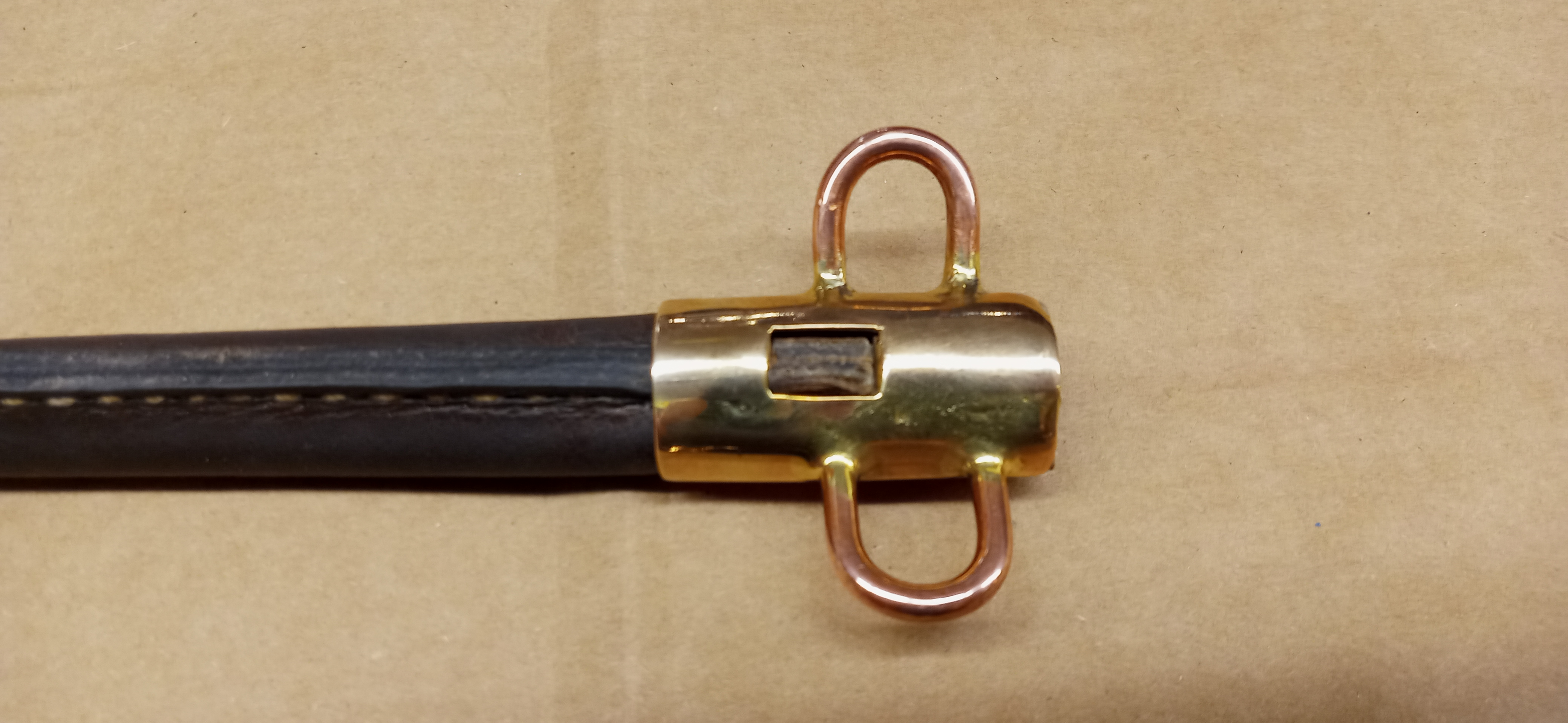
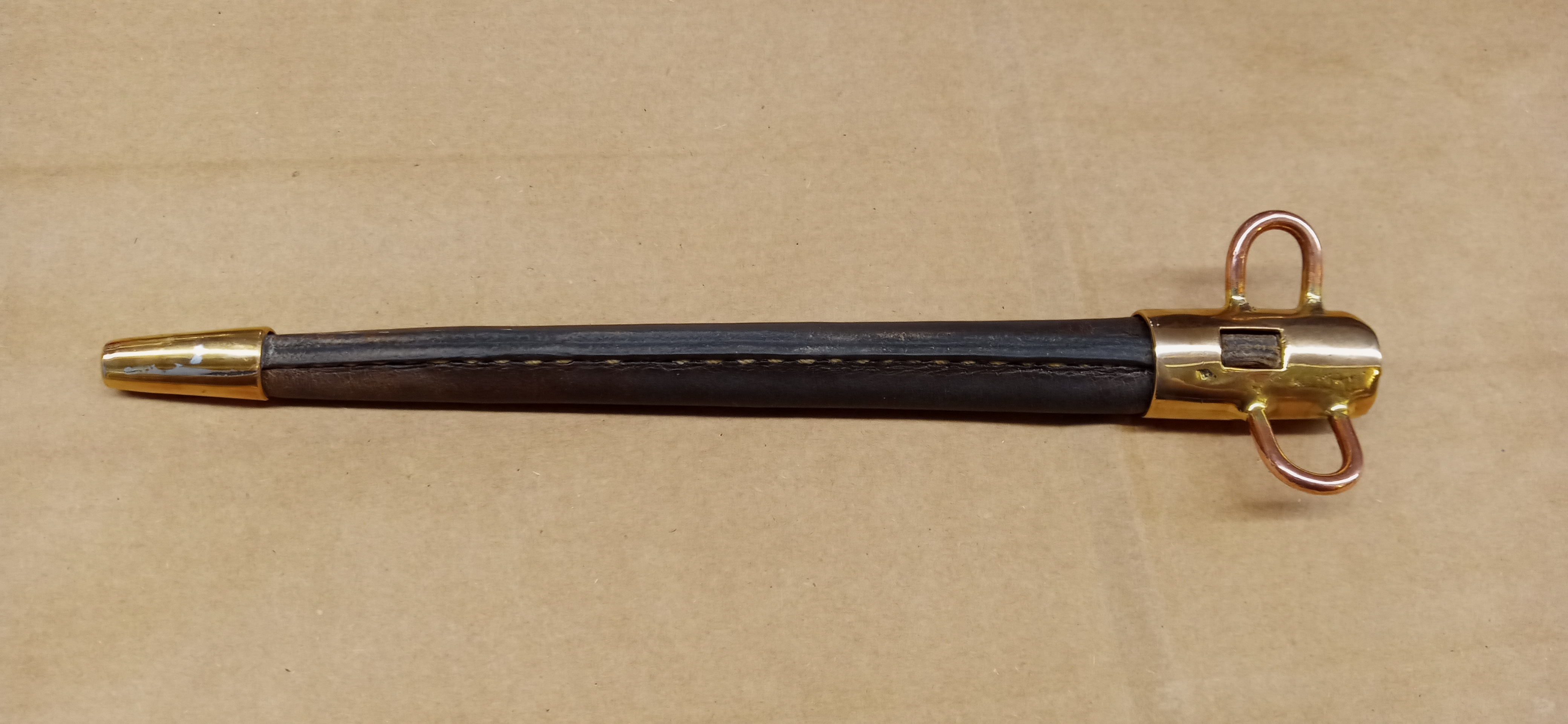
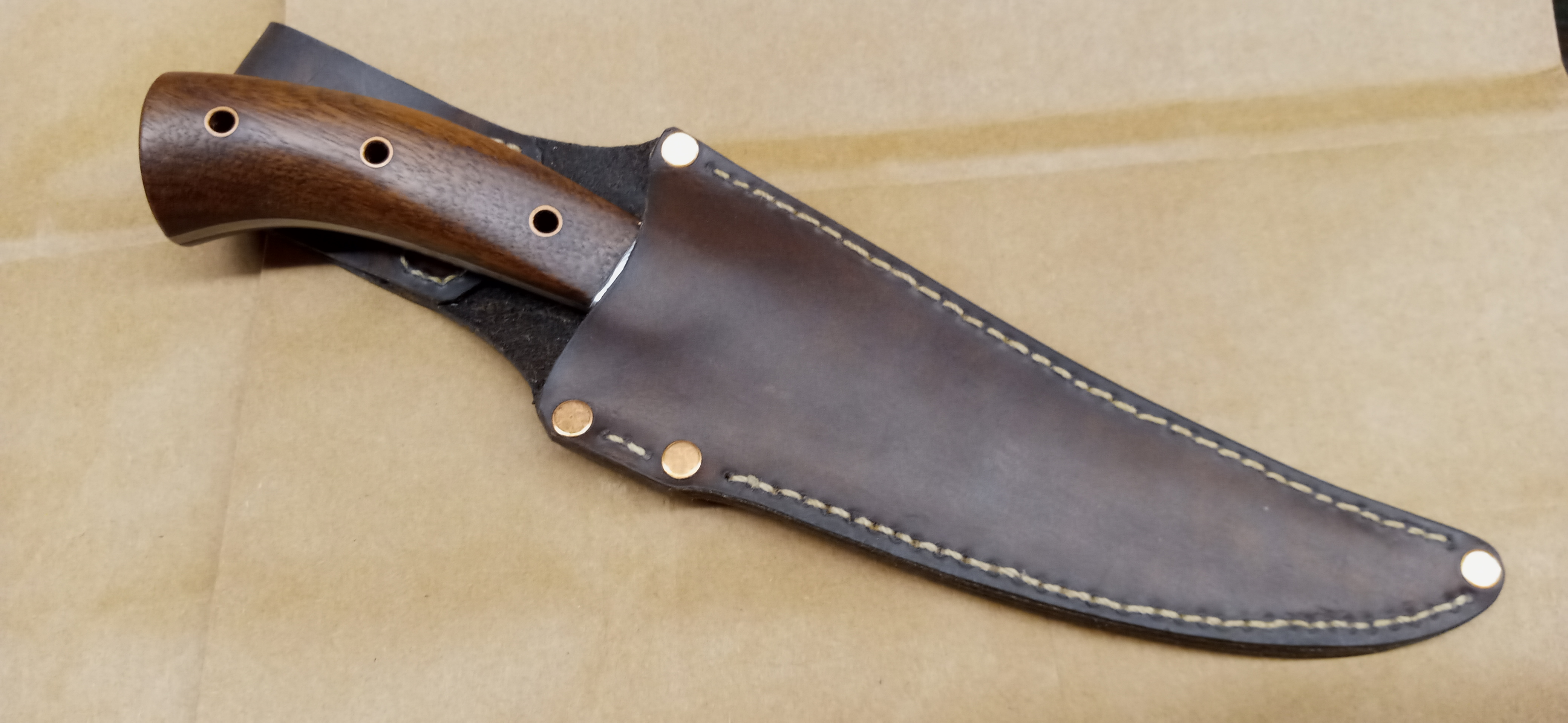
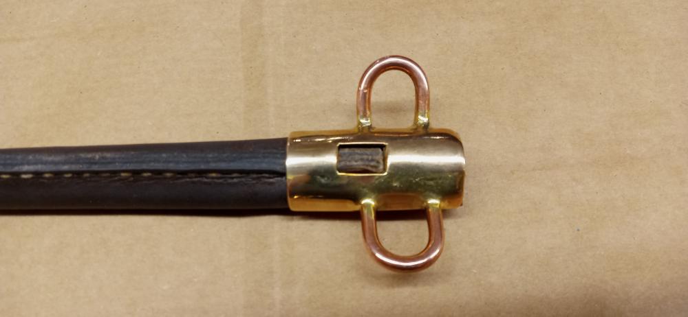
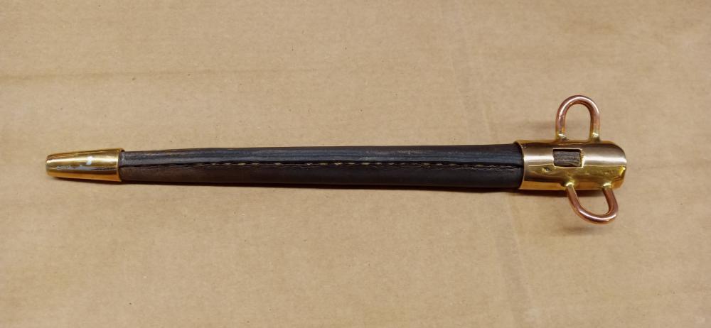
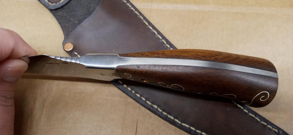
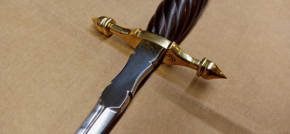
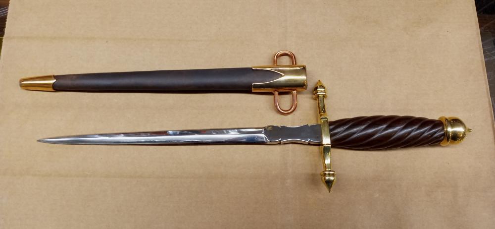
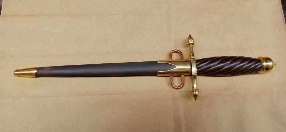
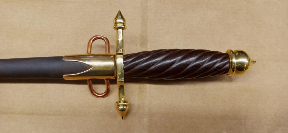
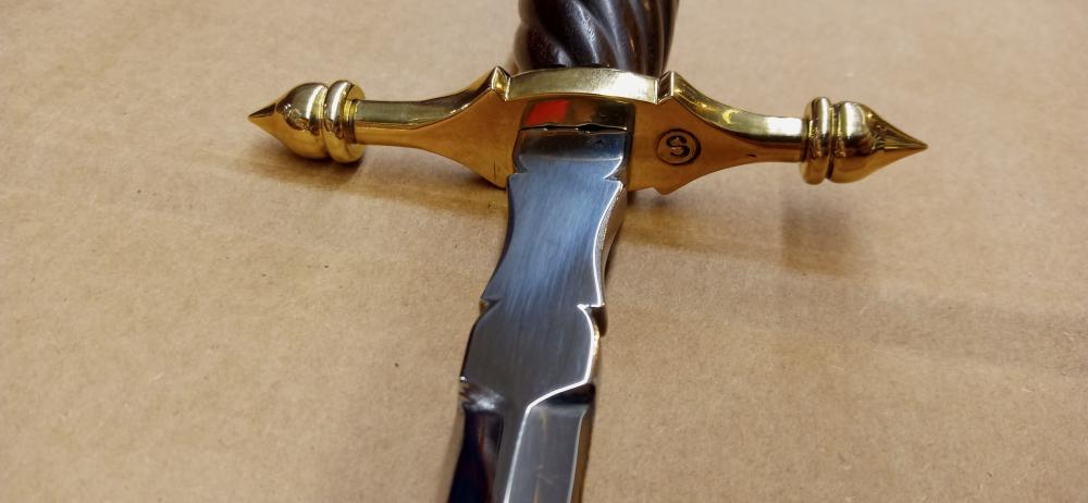
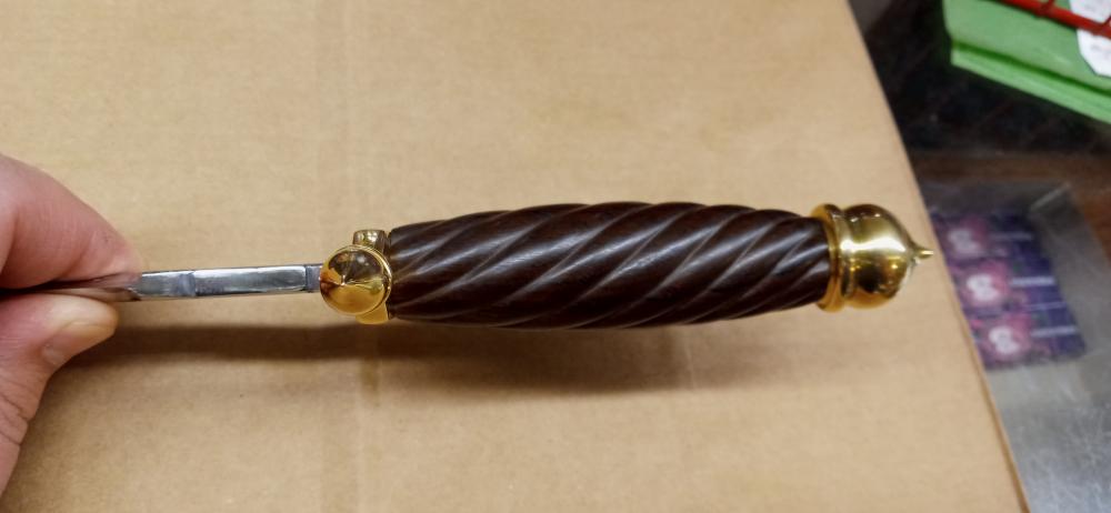
Thanks everyone, it's a very "dainty" knife for sure and the style reflects that. Probably because the persona it was made for is a lady I do like patina myself especially more of a dark brown on copper alloys, occasionally black or green as well depending on situation. To answer George's questions: The sheath is all leather with a seam on the back and the fittings are bronze because that's what I had in the right thickness, and the loops are copper because I had no brass or bronze stock for them and they won't be seen with the belt applied. The guard finials and pommel are freehand turned on the metal lathe and the guard itself is made from flat bar filed to shape before the finials were threaded on. The filed profile of the ricasso (I assume that's where you mean) was added because it needed some kind of simple detail there as it looked a bit too plain with it straight, so I just sketched on it with sharpie till something looked right! Here's some pictures of the back of the sheath to show the stitching and construction details
-
Now I feel like a neanderthal! I had mine cast from a pattern I made years ago and cleaned everything up by chipping off flash with chisels (cast iron chisels really nicely) and finishing with coarse files then finer files and a die grinder for the bowl depressions
-
walnut handled integral bolster knife
Ed Steinkirchner replied to Ed Steinkirchner's topic in Knife Making
I'm thinking his original may have been a schrade actually! Also I think many of my tools must be transparent because I can never seem to find them after I set them on the bench! -
walnut handled integral bolster knife
Ed Steinkirchner replied to Ed Steinkirchner's topic in Knife Making
Now you're just talking crazy! -
walnut handled integral bolster knife
Ed Steinkirchner replied to Ed Steinkirchner's topic in Knife Making
I thought the same thing but I did the inlay way before I did the sheath! A small lack of forethought on my part there -
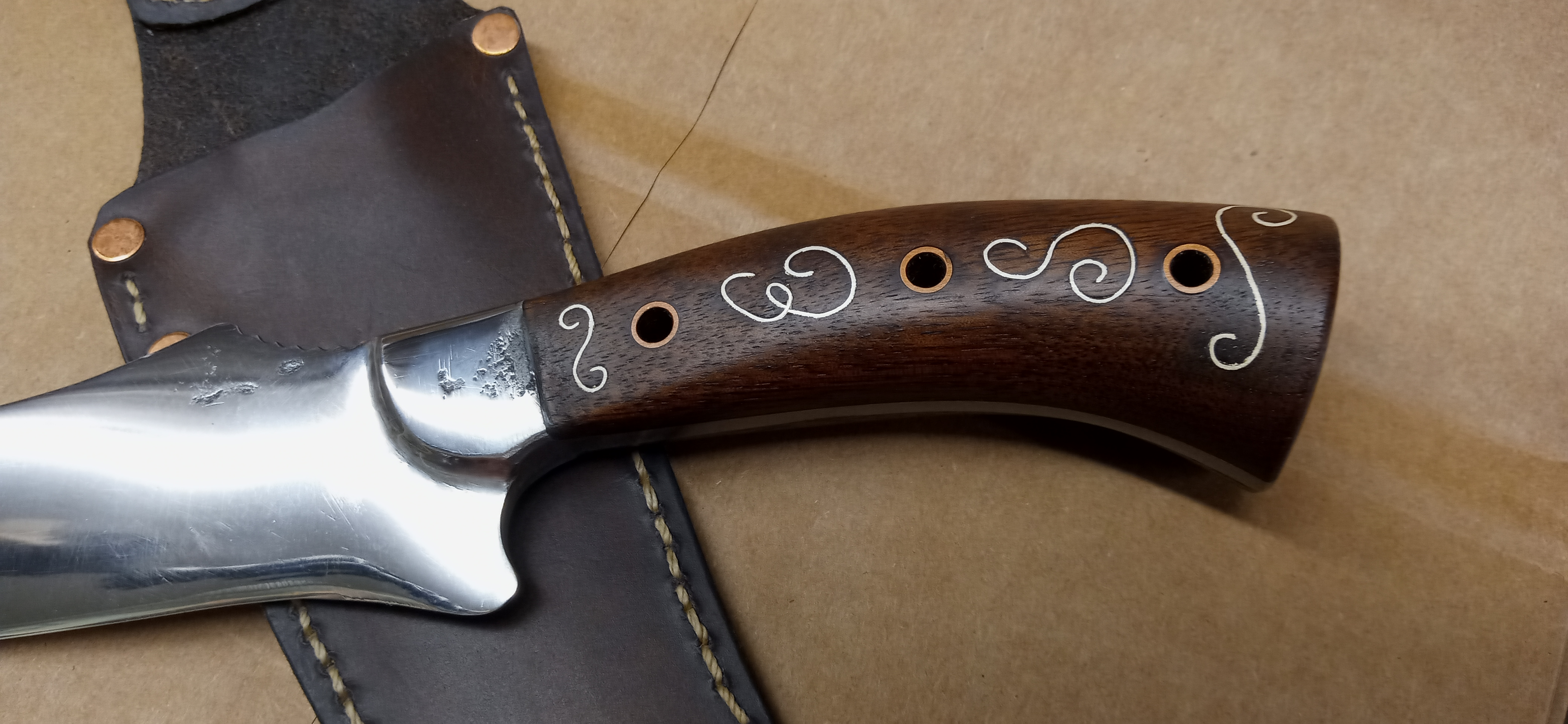
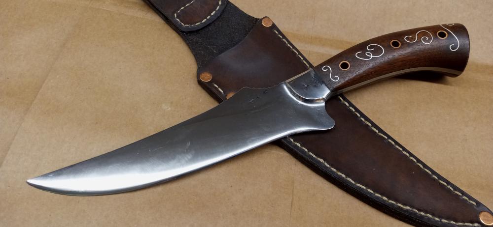
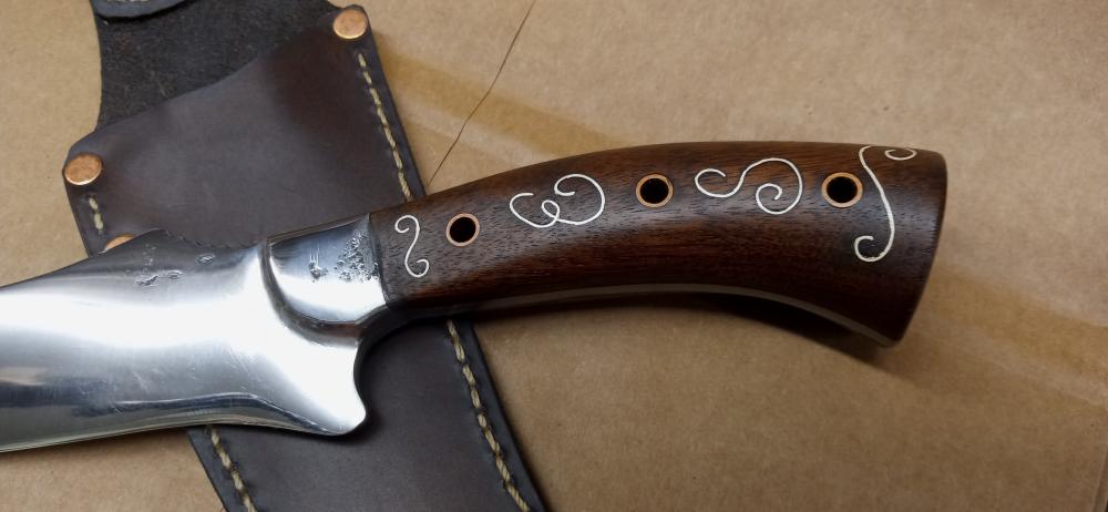
Thisknife was made as a replacement for my dad's hunting knife. He got the original decades ago and over the years it wore and chipped and was reground multiple times, the final straw was a huge chip broken out from the middle. This knife follows the blade profile of the original (although I adjusted the lines a little to make it a bit more attractive than the original) but the handle of the original wasn't great in my opinion so I changed that as well. It has the flavor of the original but with some updates. It started as a 1/2x1 piece of carbon steel, I drew out the blade to rough shape then the handle before going back to the blade for final shaping. There's a distal taper on the blade as well as the tang for balance. The scales are walnut with tubular copper rivets and are inlayed with my dad's (and my own technically) initials E.S. in fine silver wire as well as a decorative scroll above and below. Alot of "firsts" for me on this one, first time doing a full tang integral bolster, first time with this blade shape, and first time doing the wire inlay on an actual project. I'm pretty happy with the result !

-
What's your latest blade look like? Post em and let us see.
Ed Steinkirchner replied to HondoWalker's topic in Knife Making
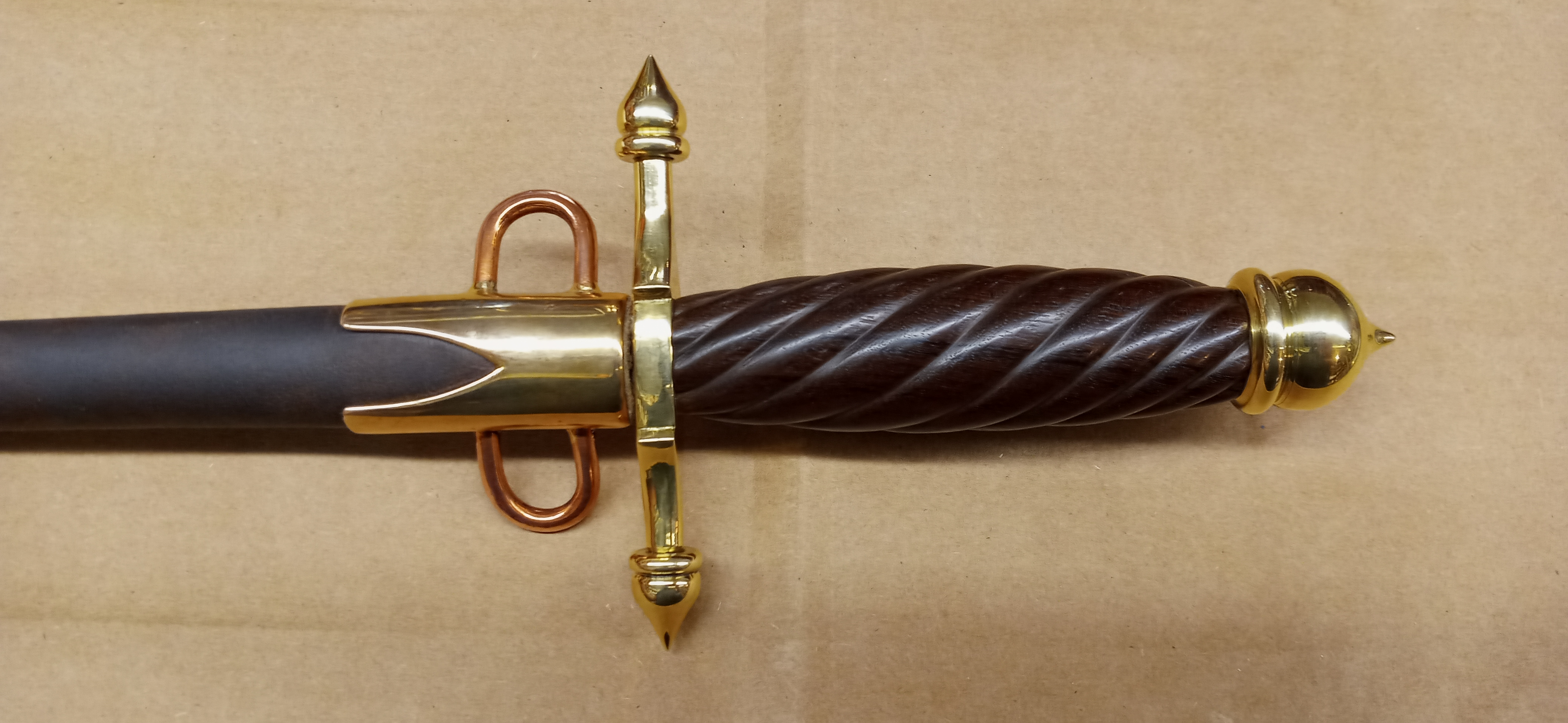
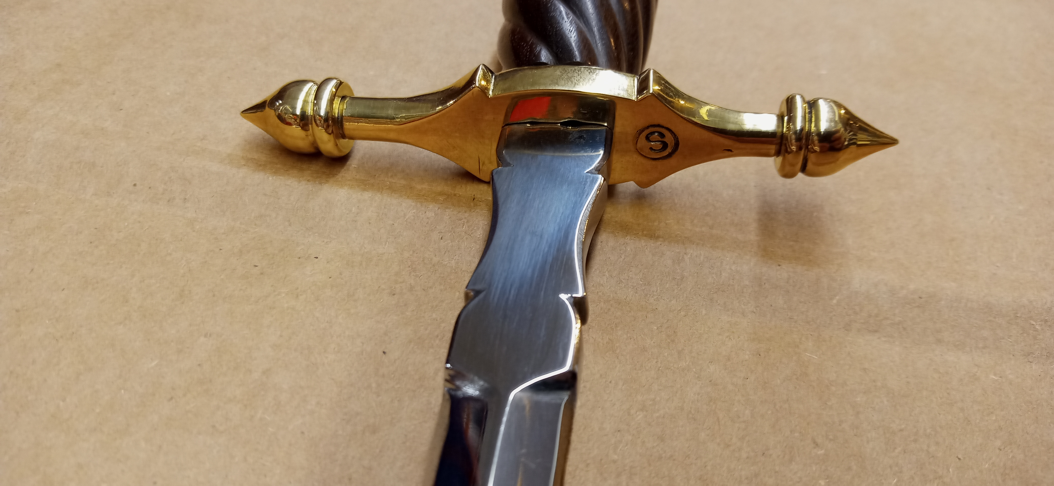
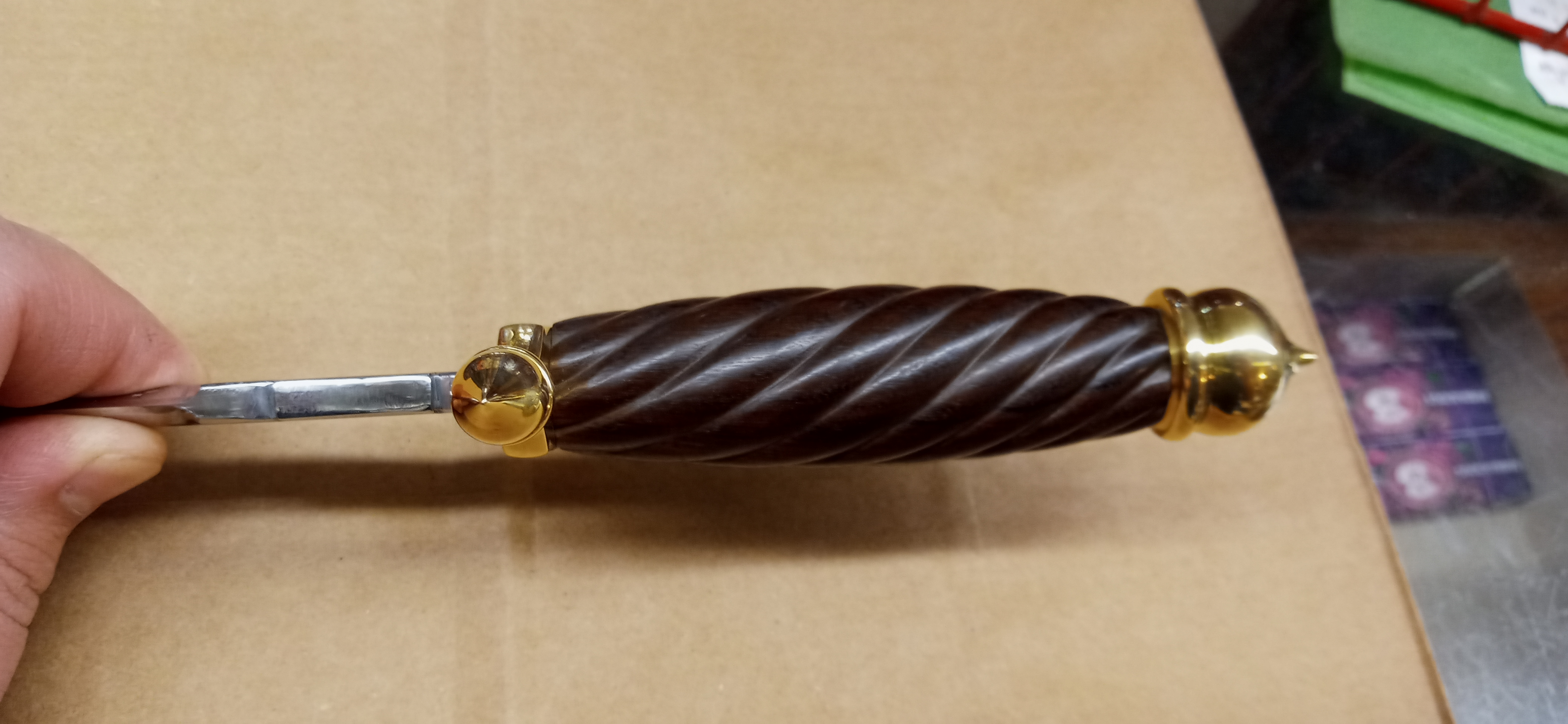
Thought I Might as well kick in on this thread, lot of nice stuff thus far! Blade is simple hc steel (1085 I believe), guard and pommel are brass, handle ebony, sheath is leather with bronze and copper fittings
-
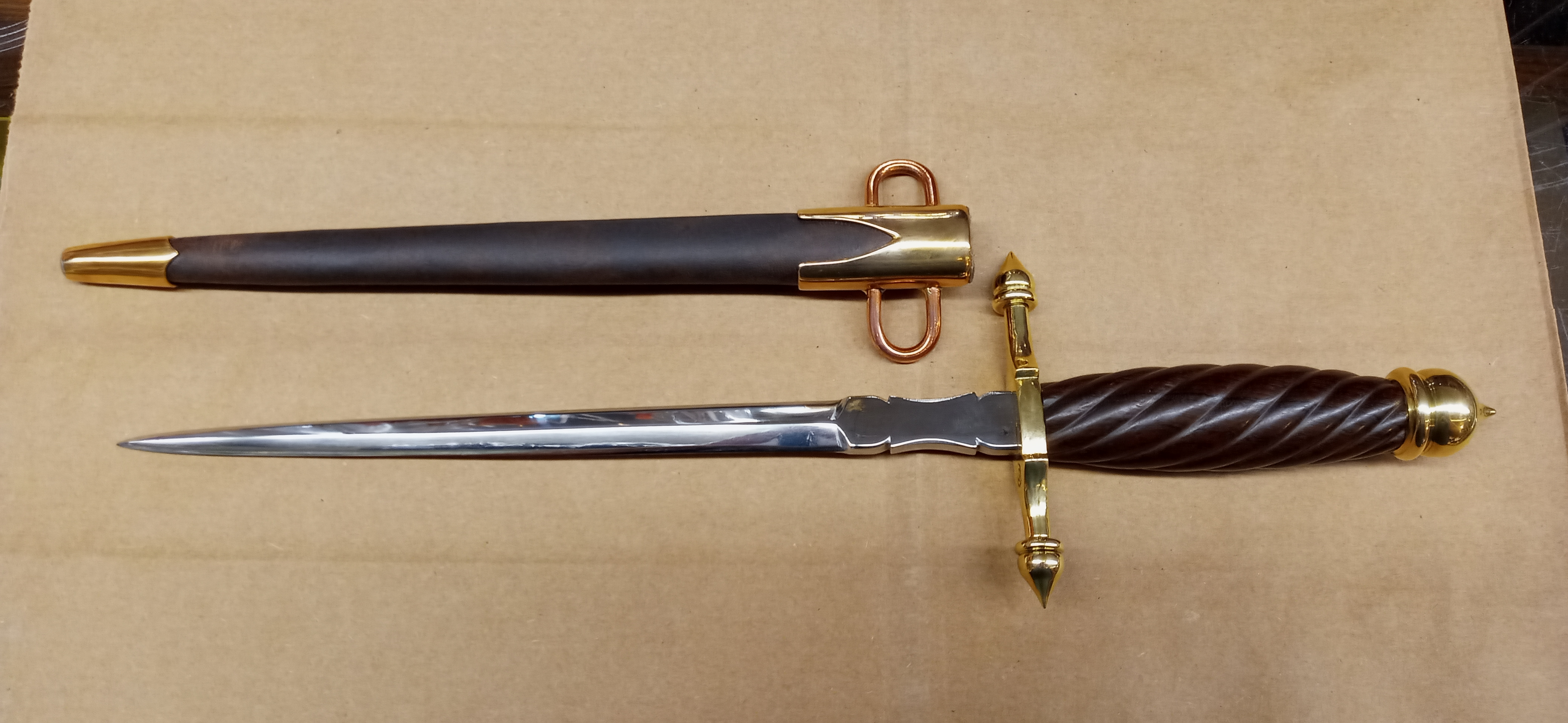
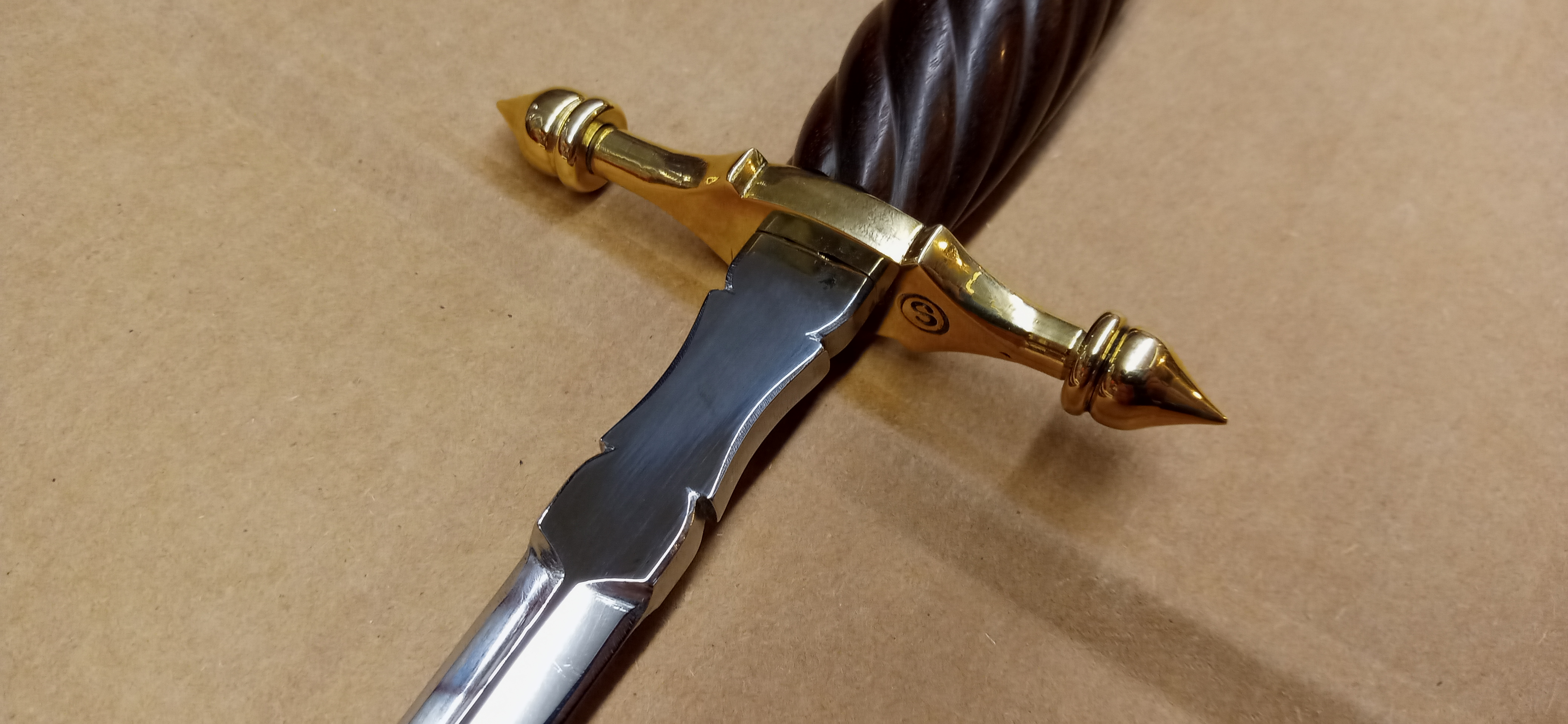
Something I recently finished, monosteel 1085, brass guard and pommel, carved ebony grip, leather sheath with bronze fittings The guard started as 1/4 x 1 flat bar that I turned the ends down on and threaded 1/4-20 then made the finials like acorn nuts. The guard was finished by filing to profile. The pommel was 1" brass freehand turned on the lathe and also threaded 1/4-20 to screw on to the tang. The sheath fittings were made from thick sheet bronze, shaped, and brazed together before finishing and polishing. The blade started as 9/16 round rod which was forged to shape then the bevels ground and file work added to the ricasso before heat treat and polishing.
-
aaaah i hadn't thought of the "pogo stick" type of spring assembly, that would get rid of the need for an additional guide for the yoke last group of pics, here before the guard was added, showing the details better. also ishould mention the 1 inch socket to the left of the bottom die to facilitate holding swages and such

-
i considered alternative things to the crank that would eliminate the side to side movement but after alot of figuring i couldnt settle on a way that was strong,buildable with my equipment, and didnt exceed my headspace and footprint limitations. i figured that the problem witha scotch yoke is in that the yoke needs its own linear guide because the spring decouples it from the ram guide, and that would add too much height. outside of the height limitations i cant see any reason it wouldnt work
-
it has very good snap to the blows, i would say comparative to a 25# LG, maybe a touch stiffer but i thing things will soften up slightly with use. the full throw is about double the crank throw. So i would say the full throw is an additional 2-3 inches up and down beyond the 4 inch crank throw, for a total whip travel of the ram of about 8-10 inches frosty: i have a short video clip actually but i dont know how to post it here.
-
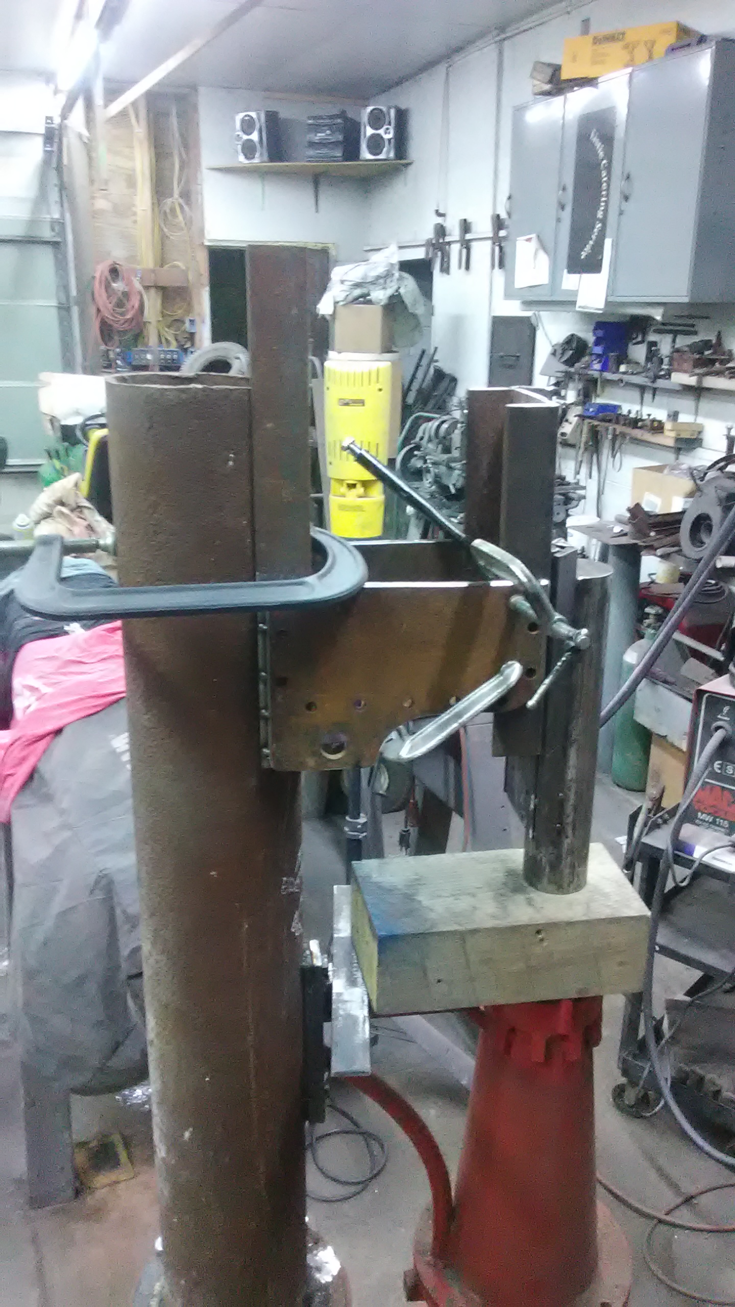
some in progress pics.


-
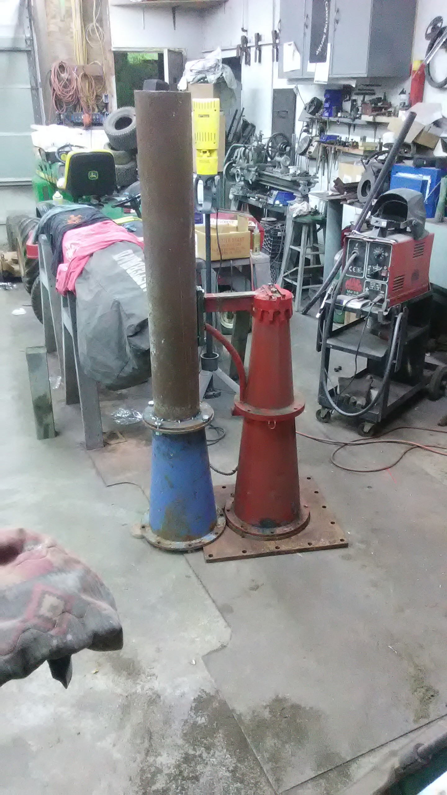
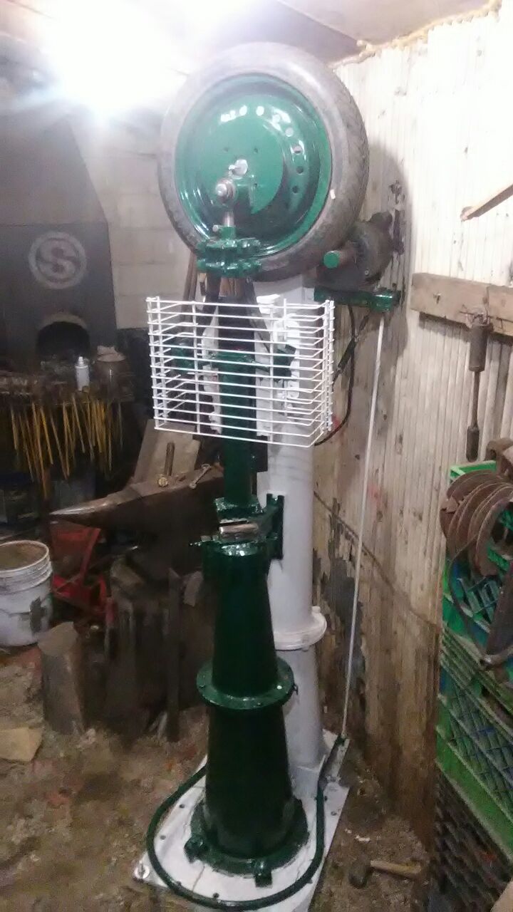
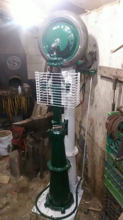
started this project around the end of august i believe, and managed to get it done about a week ago. instead of the normal tube in a tube construction of typical tire hammer tup/guides, i went with a 45 degree dovetail guide and ram, just to keep things as compact as possible to fit in my narrow and relatively low shop. i also deviated from normal tire hammer territory in the rotating assembly and crank sections. Instead of the trailor spindle i used pillow blocks and a 1.5 inch diameter shaft, in which was mounted a hub to carry the spare tire. The crank assembly is entirely separate from the wheel and hub, keyed to the shaft and removable allowing for replacement/rotation of the tire and rim in the future. Another noticeable difference, and the last major one, is the leaf spring dupont linkage (though i dont know is that still counts as a dupont) which i made by splitting a brand new small trailor spring and mounting each half in the orientation shown. a big consideration when building the hammer was the ability to disassemble it into pieces that could be moved with a dolly into the shop, so each part (except the anvil) is under 200 pounds. so here's the specs: tup weight is about 35 pounds, anvil is near 400, power is from a 1.5 HP single phase motor with a 1.5 inch pulley, the whole unit probably weighs about 1000 pounds, aand stands just over 7 feet tall. i will take more detailed pics tomorrow and dig up some progress pics as well. but i can honestly say that im extremely happy with its performance thus far!
-
i do the nick, quench, break thing myself but i add a step. After nicking it nearly through, i bend it about to 90 degrees then quench just the nicked portion so that the rest of the bar doesnt even touch the water just to minimize any chance at all of cooling.
-
i would use a narrow slot punch approximately 1 1/8 inch long and maybe 1/8inch thick , and after the hole is punched upset slightly then drift near final size before cleaning up the ring over the horn or a bickern.