DonS
-
Posts
78 -
Joined
-
Last visited
Content Type
Profiles
Forums
Articles
Gallery
Downloads
Events
Everything posted by DonS
-
Something to consider if you are planning to build a fly press or buy a screw press for blacksmithing purposes: If you use a single start lead screw, it will work much like a vise, and clamp down hard on the work piece. Then you have to let go of the work piece and use both hands to back off the wheel if you want to take a second or third run at it. By that time, the dies have sucked all the heat out of your project. I built a small fly press using a 1-1/4 inch two start screw. The two start screw is less prone to jamming up. (I originally picked up that screw to fix a leg vise, then realized that it would not hold things firmly.) It's too bad someone does not sell a "kit" consisting of a 2 inch four start screw and matching nut to build a flypress. Building the frame and ram only requires some heavy wall rectangular tubing and a decent buzz box welder. See Hammer's Blow, Vol. 13, #3 (summer 2005). Shipping a screw and a nut would be a lot cheaper than trying to ship a 600 lb machine to western Canada. If the kit was in the $100-$200 I would consider it. -Don
-
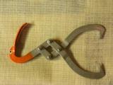
Glenn, some ice tongs have the same linkage, and some just have a pair of rings to put your hand through. If you have the kind with the rings, you have to squeeze the rings together to hold the ice. With standard size ice blocks, the rings can be made to be a comfortable distance apart. The logs I pick up are a variety of diameters, so that design does not work as well because if you make it to handle smaller logs, the handles could be uncomfortably wide when carrying large logs. Also, with the linkage shown, the heavier the log, (larger diameter) the tighter it pinches into the wood, and the handle stays relatively horizontal and can be held with heavy winter gloves.
-
I painted the handle on my log tongs so that would not loose it in the weeds. Then someone mentioned that it looked like it had a beak, so I added eyes and teeth...later I realized that birds probably don't have teeth except in cartoons. On a similar note, I added a bird's head to my post drill, since it already had the perfect animation.
-
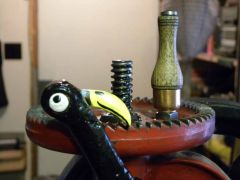 After watching the way it moved, I thought it just HAD to have a bird's head painted on it.
 -
Sorry, it looks like you can't attach a picture directly. I will try the URL method. Don
-
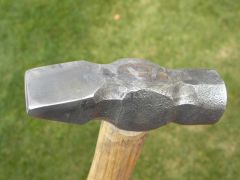 1 - 3/4 pounds
 -
Nice work on that hammer! You are setting the standard real high. Here is my version of a cross pein hammer that I just completed with the help of one of our guild members (Dennis G). It came out as 1 3/4 pounds. The face turned out to be a bit soft, but maybe it will work harden over time...I already have the handle attached.
-
I was going to weld a piece of pipe on for a handle, but forming a curve in the swage block and then bending the handle out of one piece was easier than setting up the welder. Don
-
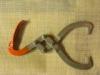
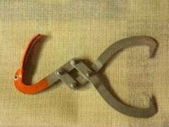 Tongs for carrying logs. made of 1 x 1/4 flat bar and held together with 1/4 inch bolts and nylock nuts (instead of rivets) so that they can be adjusted for smooth operation.
 -
We used to buy coal in metal drums from one of our guild members. The coal was essentially coal dust and small pieces 1/4 inch and smaller (fines), so that might affect the weight, but our barrels supposedly held 400 pounds. We paid $100 for the coal and $20 for the barrel. The coal came from the Cadomin area West of Edmonton. We have used up all our supply, and have been searching for a new suppliy. I tried the Gregg River and Cardinal River coal companies and they are not interested in selling anything less than a train load. I am going to try the other source at Grande Cache to see if they will sell us a truck load. We are currently buying smithing coal from Home Hardware at about $60 for a 50 lb bag of east coast coal. Excellent to work with, but a bit pricy. -Don- Western Canadian Blacksmiths Guild
-
I made an "anvil" out of a piece of rail back in high school. I cut it into an anvil shape with a torch and drilled a few holes in the top as pritchel holes and to hold dowels for bending. I started cutting the top flat with a hacksaw because it had quite a crown to it. After about 2 inches I gave up, and used it for the next 20 years on the workbench mostly for flattening or straightening things out cold...then I took a blacksmithing course and found out what a real anvil was like. Unable to find a real anvil, I thought that I should finish what I started back in high school, so I continued to saw the slab off the top of the rail and ground it flat. That took many days of hacksawing, only to discover that the top was now much softer than it used to be. It was time well spent though, because this became the seed anvil that led me to a 150 lb cast steel anvil about 6 months later. The rounded part that I cut off was probably work hardened. I usually work on small stuff under half-inch square. If someone is using the "real" anvil in the shop, I find that there is nothing wrong with using a scrap of steel held in the vise to do some small forgings. If you can't find an anvil, use a piece of rail and scale your work accordingly. If you have a good vise, you can do plenty of blacksmithing since it can hold scroll jigs, hardies fullers and bicks. A 6-inch mechanics vise is pretty hard to break with a 2-1/2 pound hammer. If you can find a 40 or 50 lb leg vise, use that. Around here they are easier to find than an anvil, and certainly a lot cheaper.
-
I built a Rusty-type hammer: 34 lb running a bit over 200 beats/minute. The motor is a 1 HP TEFC Frame 56-75 and draws 13.4 amps under rated load. 1725 rpm. When I first got the hammer running, the motor ran hot. I checked the amps and it had current spikes up to 25 amps. I added some weight to the large pulley as a flywheel, and now the motor runs cool. I have a "large pulley" that is 12-3/4 inches in diameter. The motor pulley is 2 inches O.D. and I don't think you can get a smaller pulley that will still fit the 5/8 inch shaft. Fortunately it gives me the right speed. If you find a motor with a 1 inch shaft, you may have to settle for a larger pulley on the motor which will require a larger pulley on the hammer. I don't know if this is an issue for you. Some of the other variables besides Ram Weight and beats/minute that will determine the necessary HP would be the length of the stroke or velocity of the ram at impact, and the overall efficiency of the hammer. Good luck with your project.
-
I have a "Rusty" type mechanical hammer with UHMW guides. I spray the ram (polished square tubing) with a light coat of 3-in-1 silicone spray. I noticed that the beats per minute increases slightly after I spray the ram, so it must help. I mostly lube the ram to keep it from rusting though. So far (in 2 years) the silicone has not harmed the UHMW).
-
Hello Nezeal, The Western Canadian Blacksmiths Guild meets on the second Saturday of the month, i.e. April 11 at about 10:30. The location is the Alberta Heritage Exposition Park, which is located 6 km east of the Leduc Walmart. From Highway 2, go 6 km east on Highway 39 (towards Drayton Valley) at Cohn Dale Road go north about half a kilometer to the gate. Follow the road through the park over the railroad tracks to the blacksmiths shop. You are welcome to join us in the shop.
-
Uncle Spike: I just measured the springs on my hammer, if that would be of any help: Ram Weight: 34 Lb Stroke: 7 inches (moving it by hand, without the overshoot at normal speed) Spring material: 5/16 x 2-1/4 inches Main spring: 39 inches long Upper and lower springs: 24 inches long The three leaves are clamped at the back end 9 inches off center They are not clamped together at the front end. The main and upper springs are in contact the full length There is a 1/4 inch gap between the main and lower spring at the front of the pack, so that the ram is not restricted by the springs as much at the bottom of the stroke. At rest there is about 3/4 inch of daylight between the dies. The pitman arm is attached 2 inches from the back end of the main spring, and the rollers are about 4 inches from the front end of the main spring. I left the curve in the springs just as they came from the spring shop. The pitman arm is tilted back a bit so that it is still perpendicular to the spring. This move the flywheel foreward a bit, reducing the overall footprint of the machine. I actually added a bit of additional curve to the lower "helper" spring so that the hammer would still hit hard with a bit more daylight between the springs. I have not seen anyone else use these relatively short springs. Everyone else seems to use longer springs and has had good success. I had some trouble initially, which I thought was due to the short springs, but it turned out that I had insufficient weight on the flywheel (only a cast iron pully) I added a one inch x 13 inch disk to the pulley and everything went smoother. I had a 250 lb anvil initially, plus the weight of the 1-1/4 inch baseplate, but that was insufficent. Performance was poor, until I added an additional 300lb baseplate and bolted it all firmly together. Total equivalent anvil weight (of the anvil and metal within an 8 radius of the anvil center) would be about 350 lb or a 10:1 ratio, and that improved it significantly. Hope that is of some help. Don Sinclaire in snowy Edmonton
-
Power Hammer Test Results I finally got around to testing my 34 lb Rusty power hammer using the tests some of you have tried. 5 blows: 0.906" 10 blows: 0.832" The material was 0.999 x 0.999 cold rolled steel heated to a yellow heat, but not quite a welding heat. I also tried this test with my 66lb treadle hammer, delivering the hardest blows I could. 10 blows: 0.780" The length of the bite was hard to control while delivering these blows, and turned out to be about 1 3/4 inches with the treadle hammer instead of 2 inches. My "Rusty" hammer is more in the league of the 25 lb Little Giant, although the Little Giants probably run faster than my 220 blows /minute, and as a result would do more work. I am a bit disappointed with my results; I thought it would do better, based only on my previous experience with this hammer and never having used other mechanical hammers. (Ignorance is bliss).
-
The Wetern Canadian Blacksmiths Guild is alive and well, but out website is down currently. If you are located near Edmonton, you can come to the next meeting which is on the second Saturday of the month. We meet at the Alberta Heritage Park run by the West Leduc Antique Society. It is located a few miles west of Leduc. I can give you directions if you want. If you are closer to Calgary, there is a guild chapter there too, and I can get you a contact. Please let me know which site is more convenient, an I will provide more details. Sorry about the website being down.
-
There are actually two blueprints for the Jr Strasil helve hammer. I don't know if you found both of them. Try BP 63, which is the original hand drawn version, and BP 159 which shows the detailed photos. There are all sorts of gems of info in the BP 63sketches and in the BP 159 text. I have a "Rusty" hammer, and it works quite well, but I would also like to build this helve hammer just to see how it compares to the Rusty. I have all the parts except for the large pulley and the 2-1/2 inch square tube for the post that holds the upper bearings. The helve hammer shown in the blueprints is relatively light, possibly 10-15 lb hammer weight, but it is reported to work ok (because of the velocity of the blow since it is accellerated by the spring at the back). The helve hammers run by water power are raise up by a cam and then allowed to drop under gravity. They depend primarily on the mass of the hammer, which I assume would be hundred lbs plus at a relatively low velocity. The associated anvil would have to be correspondingly large for this to be efficient. I really like the simplicity of the Strasil helve hammer. The only disadvantage I can see is that the die faces can't be parallel for all thicknesses of material being worked, so the faces are slightly curved. Looks great for drawing out and general work, but maybe not ideal if you want to use tooling. You will need access to a decent size welder. A buzz box will do, and some new/dry 7018 AC rods if you are buiding it out of scrap that could include some alloy steel, as in my case. My proposed base is some sort of AR grader blade stock and I have no idea what the 5 inch dia anvil shaft is made of. I can keep you posted on my progress, (which is usually slow). Good luck.
-
Gobae: For practical purposes there are two kinds of motors used in the shop, and you have identified both of them: the induction motor (no brushes or commutator these days), and the universal AC/DC motor that has brushes and a commutator. The induction motors in your shop are likely either 2-pole or 4-pole motors. They only run on AC power; 60 Hz in North America. If the motor has no load on it and has perfect bearings, it would run at close the synchronous speed: 3600 rpm for 2-pole or 1800 rpm for 4-pole motors. They develop no torque at this speed. Induction motors require "slip" in order to develop torque, so as they slow down (within reason), they develop more torque, and torqe x rpm is proportional to the horsepower produced. Maximum slip would be in theorder of 5-10 percent. Beyond that, these motors tend to stall. This is why these motors are rated at, say 2 HP at 3450 RPM for a 2-pole motor or at 1725 RPM for a 4-pole motor - the standard speed ratings under load for these types of motors. If the motor has a "continuous duty" rating, it can run at this speed and produce the rated amount or Horsepower all day long. It will draw the peak load current printed on the nameplate. If you load this motor down more, it will run a bit slower, resulting in more slip below synchronous speed, and will produce more torque. As a result, it will produce more horsepower, and suck more current. On a cheap motor, the heat generated by the curren flowing through the (barely adequate) windings will cause the motor to overheat and trip the thermal switch or burn up. On those heavy motors you mentioned, they probably have extra-heavy windings, heavy castings, and plenty of surface area to radiate the heat, so they can probably produce twice the horsepower listed on the nameplate and just over twice the torque without burning up. They will no longer be running at the standard rated speed of 1725 rpm though. Induction motors have a torque curve that peaks around 1700 rpm (4-pole motor) and drops off very rapidly below that. You have probably noticed this on your bench grinder. You can load it down and the motor slows down a bit. Load it down a bit more and it suddenly stalls. Universal AC/DC motors run at a much higher speed, say 5000 rpm, limited by the windings and internal friction. Torque increases as the speed drops, but these motors can be loaded down to a much lower speed before they stall. They can produce lots of horsepower, but the rpm may vary all over the place. As they are loaded down, the current through the windings increases. The heat generated is proportional to the square of the input current, so as you go over the rated current, lots of heat is generated. Universal motors are usually compact and light weight, and need a lot of air movement. If you load them down, the rpm drops off, and the cooling fan moves less air. They overheat rapidly and as a result, burn out easily. Since universal motors run at a relatively high rpm, they are often coupled directly to a gear box as in a skill saw to get the rpm down and the torque up to a usable level. As a result, both induction and universal motors can produce the same 2 horsepower, but when overloaded a bit, the induction motor can hang in there for a long time. The universal motor can outperform the induction motor in a heavy torque application, but only for a few seconds. You also mentioned flywheels: A flywheel can average out the torque requrements of the load, presenting a lower peak torque requirement to the motor. A typical example is a compressor or a power hammer. If you don't have a flywheel on a compressor, you can use a huge motor and overcome the compression stroke, but it is more effective to smooth out the load with a flywheel and use a smaller motor.
-
HP is just RPM x Torque x a constant, so torque is directly proportional to Horse Power at any given RPM. Starting torque is an other matter, and some motor designs are better than others. I have a 34 Lb "Rusty" type hammer. I just measured the RPM and Load current: Present speed: 198 BPM Motor Type: TEFC, frame 56-75 (a bit less efficient than some others) Voltage: 115 VAC Rating: 1 HP Speed: 1725 RPM under load Full Load Current: 13.4 A at 115VAC Present hammer speed: 198 BPM Measured current: 10A at idle, 13-14A at full speed of the hammer. As I mentioned in an earlier posting today, I had too small a flywheel initially, and the motor ran hot and made the needle on the clip-on ammeter swing between 10 and 26 A! Now that I have upgraded the flywheel, and the motor is running close to the specified full load current, I suspect it is delivering close to the rated 1 HP. The guides are UHMW and I give the ram a shot of silicone lube from time to time, so friction or viscous damping due to heavy oil is minimal.
-
Appalachian Power Hammers
DonS replied to larrynjr's topic in Power Hammers, Treadle Hammers, Olivers
Although I would be inclined to build a tire hammer, I don't want to discourage anyone from building a "Rusty" type hammer. They are quite popular, and seem to work well. It may all come down to the scrap you find. Some more thoughts on building a Rusty hammer (all stuff that I had to learn the hard way): Counter weights: The tire hammer and the Little Giant hammers have counter weights in/on the flywheel. The weight reduces the side-to-side vibration caused by the top end of the toggle link assembly moving from side to side. This is important because the motion is from side to side along the narrow part of the footprint, it is up high, and the weight of the toggle links is significant. The counterweight should be about half the weight of the toggle link assemby since only the upper part moves from side to side. The Rusty hammer does not really require a counter weight because: 1) you have to compensate for only half the weight of the pitman arm, which is light 2) the vibration is front-to-back along the major axis of the baseplate, and 3) it is down low. You can't balance out the up and down part of the motion. Don't even try. Anvil size: My hammer has a 34 pound ram/die assembly. The anvil is 250 lbs. When I had the machine sitting on the garage floor, it seemed to work OK as far as I could tell, but shook the floor and stuff started falling off shelves. (Anvil to ram ration about 7.5 to 1.) Since I have limited space, I thought I would place it on a small trailer and wheel it into the garage when required. Even with the jack stands extended the strength of the blows seemed to be only half as effective as when the hammer sat on the concrete. I gave up on the trailer concept and decided to make a permanent bench to mount the hammer on. I used a steel slab on short I-beam legs. Total weight of the bench is about 350 lbs. If I include half that weight as part of my anvil (only the part directly under or near the anvil) the effective weight of the anvil becomes about 400 lbs and the anvil-to-ram ratio becomes close to 12:1. I have a 2x6 and a piece of rubber belt under the feet of the bench to cushion the concrete a bit. It hits real solidly now, and confims what others have been saying about the importance of the anvil to ram weight ratio. Flywheel: My flywheel consisted of a 13 inch cast iron pulley (2 groves) and a 6 inch dia 3/4 inch plate for the crank pin mount. The associated problems with such a light flywheel were: 1) The 1 HP motor ran hot. The clip-on ammeter registered double the rated current on part of the revolution, and idle current on the rest of the revolution. 2) The small pulley on the motor ran hot, even when I did not slip the clutch. 3) The flywheel almost seemed to stall momentarily on parts of the cycle. Probably causing the belt to slip a bit even at full speed- overheating the small pulley. 4) Changing the size and number of leaf springs and location of the clamps in order to "Tune" the hammer seemed to have unpredictable results. I eventually settled for a fairly limber spring with softer blows and 180 beats per minute max speed. Last week I replaced the 6 inch crank pin disk with a 14 inch dia piece of 3/4 inch plate, increasing the weight of the flywheel from about 15 lbs to 45 lbs. This fixed all kinds of problems. I even went back to stiffer spring by adding an upper and lower "helper" spring to the pack. As a rule of thumb, I would say that the flywheel (assuming it is about 13-14 inches or larger in diameter) should be at least equal in weight to the ram. Bigger is probably better, but if it is too heavy, starting and stopping the hammer will be slower, making it more difficult to strike a single blow. The flywheel and clutch on a 25 lb Little Giant looks to be about 100 lbs or more, and when a stock Little Giant stops, it seems to coast to a stop. The tire hammer has a 50 lb ram, and the spare tire and associated metal work probably weighs 50 lbs or more as well. Due to the large diameter and the wight distribution of the tire, it is a very effective flywheel. Spring Assembly: I hade one main leaf sandwiched between a pair of shorter leaves, and clamped them together a usual. The gap between the dies (at rest) was about 1/2 inch. I got full power blows on 1/2 inch material, but on thin stock, the blows were softer, because the (relatively stiff) spring starts to absorb some of that energy as the dies get close. I really wanted to increase the gap to 1 inch so that I could get some tooling or thicker stock in there. I solved this by clamping only the back end of the leaves together, and leaving the front end loose. I curved the lower helper spring so that it did not have any effect until the dies actually touched. That way, the spring assembly was stiff at the top end of the stroke, weaker at the bottom of the stroke, and still gave support to the main leaf when it started lifting the ram back up. The resulting spring is "non-linear". This is also what the toggle links provide on the tire hammer and Little Giant hammer, but in an even more effective way. At rest you can easily bounce the Little Giant ram up and down a bit by hand, but as the ram gets deflected more and more, the spring becomes stiffer and stiffer because of the geometry of the links. It is probably cheaper and easier to build a tire hammer than to restore a Little Giant if it is in rough shape. The Little Giant will probably have a higher resale value just because it is a cool-looking old machine that has a lot of followers. I bought a couple of 30 inch x 8 inch dia pieces of steel at the scrap yard in order to build an air hammer and a tire hammer, but with the recent improvements in my "Rusty" hammer, I will put that on hold....still thinking about a small helve hammer though. -
Appalachian Power Hammers
DonS replied to larrynjr's topic in Power Hammers, Treadle Hammers, Olivers
The newer versions of the tire hammer have a brake. The motor is mounted on a pivoting bar. Stepping on the treadle moves the "Pulley" end of the motor up to contact the tire. When you take your foot off the treadle, that end of the motor drops back down, and the other end of the bar moves up. This end of the bar has a plate welded on it that contacts the tire and acts as a brake. I have never seen a Tire Hammer, but I really like the small footprint. (I built the Rusty leaf spring hammer, and found that it takes up quite a bit of space- about the same as my treadle hammer. (About 32 inches x 18 inches wide.) I have some left-over steel that is too small for a large power hammer (36 x 5 in dia.) so I am thinking of building a helve hammer as described in the Blueprints by Jr Strasil) just to see how it works. By its nature, the helve has to have slightly curved dies- good for drawing, but it is nice to have parallel flat dies for some work. I have combination dies on my Rusty hammer, and like the flat part for use with flatters and fullers. -
Treadle hammer build pictures
DonS replied to Sam Salvati's topic in Power Hammers, Treadle Hammers, Olivers
I noticed the Anti Flag T-Shirt! The band was here in Edmonton yesterday. -
I use molybdenum disulphide grease (the stuff that smells bad, like suphur) for the screw and the spherical washers. Moly grease is good under extreme pressure. The best thing you can do for your leg vise is build a heavy sheet metal guard for the screw. Most leg vises have the screw exposed right under the opening of the jaws- not a very good design. An inverted U-shape piece that lays over the screw and extends into the hole in the front jaw. A small 1/4 x 3/16 inch tab in the front end of the guard rides in the screw thread and keeps it in place. The guard keeps the grit from getting into the grease and into the threads of the screw. It also protects the screw from having something driven into the top of the screw by mistake like when you are upsetting a piece of steel that is nicely centered over the screw. I used 14-gauge steel and bent it hot over a piece of pipe the same diameter as the screw. Make the sides that drop down long enough to keep the guard upright. Make a template out of a Cornflakes box and trim to fit. Check the size of the hole in the front jaw to make sure there is enough clearance throughout the travel of the jaw to accommodate the thickness of the guard.
-
Motor for Appalachian style hammer.
DonS replied to simmonds's topic in Power Hammers, Treadle Hammers, Olivers
Simmonds: As I mentioned, I considered my hammer "OK" in that it draws out 3/4 or 1 inch bar a lot faster and easier than by hand. All I can compare it to that I have briefly used, is a 25 lb Little Giant, which hits about a hard but with many more blows per minute, and a 100 lb Alldays & Onions self contained hammer which is in a whole different league. I have my hammer set up with at 1/2 inch gap between the dies when it is at rest. It works material in the 1/2 inch to 1-inch range quite well, but the blows are a bit softer on thinner material since the spring is already pulling up as the dies get that close. The spring constant is a linear 500 pounds per inch of deflection (on my hamer) so when the dies touch, the leaf spring is pulling back by about 250 pounds. That is the nature of this type of spring. The little giant uses a toggle link and the action is very loose in the center of the stroke and only gets stiff at the extreme ends of the stroke, so it is less sensitive to stock thickness. Those builders that used longer leaf springs than mine seem to have a more limber action and they seem to be quite pleased with the performance. Jeff Reinhard, who posts on Anvilfire and Forgemagic built a similar power hammer, with the belt and pulley drive, and switched to the spare tire drive, and recommends that as the better design. Those compact spare tires are quite heavy and would act as a good flywheel. They are also cheap, usually in new condition and readily available at the auto wreckers for $5-10. For a bearing assembly you can use a matching hub from the rear axle of a fron-wheel drive car. Some suggest a Plymouth Grande Caravan rear hub (also cheap and available). I have used Plymouth Horizon rear hubs which are nice because the back mounting face is flat- you just have to bolt it down to the support column with four (metric) bolts. I got my springs at an automotive spring shop. They had all kinds of widths and thicknesses in various lengths. They were all pre-curved though. I don't know where you can get straight pieces, but being curved does not seem to be a big problem. The geometry does change a bit since the pitman arm should push perpendicular to the end of the spring, and the front end of the spring at the rollers, should be perpendicular to the ram at mid-stroke. If you are using a drill press to drill the holes, consider adding a few extra holes to allow for adjustment later. It is a lot easier at that point than after it is partially assembled.