

DonS
-
Posts
78 -
Joined
-
Last visited
Content Type
Profiles
Forums
Articles
Gallery
Downloads
Events
Everything posted by DonS
-
Motor for Appalachian style hammer.
DonS replied to simmonds's topic in Power Hammers, Treadle Hammers, Olivers
Simmonds, I just posted some drawings and pictures of my power hammer. I built it about 2 years ago. It works OK, but is not spectacular, probably because I made the springs a bit too short (due to limited space). I used a relatively short anvil and initially had it on a trailer so I could move it out of the way. That did not work out so I placed it on a heavy bench, high enough so that I couls park the lawn mower under it, again due to a space problem. Have a look in the Gallery under recent uploads or under DonS. -
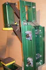
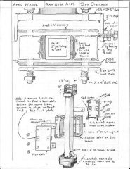 Here is how the ram guides were assembled.
 -
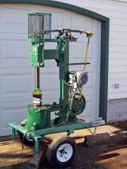
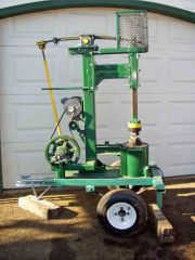
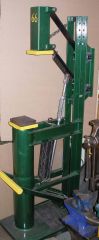
 Here is the completed installation of the power hammer. It now sits on its own stand, which adds about 300 pounds to the total weight and rests firmly on the concrete floor. Hits much harder than when it was on the trailer.
 -
-
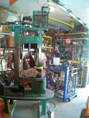
 This is the power hammer sitting on the trailer so that I could move it around. The trailer idea did not work out. Even with the jacks extended and sitting on hardwood blocks, the base was too springy and it significantly reduced the force of the blows.
 -
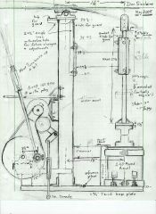 Here is a drawing of my power hammer based on the Rusty hammer. 34 pound ram, 1 HP 1760 RPM motor, 13-1/4 inch large pulley and 1-3/4 inch (effective size) motor pulley. Anvil is 240 lb. Dies are made of 5 inch dia 4340.
 -
Motor for Appalachian style hammer.
DonS replied to simmonds's topic in Power Hammers, Treadle Hammers, Olivers
I built a Rusty-type hammer with a 34 pound ram, and it runs at 220 beats per minute. My flywheel is a 13-inch two-groove cast iron pulley, and the motor has a two-inch pulley that has the grove cut wider so that the belt rides a bit lower, more like a 1-3/4 inch pulley. My motor runs at about 1750 RPM. 1750 x 13 / 1.75 = 237 RPM My measurements are not exact, but close enough for this. The motor shaft is 5/8 inch, and the smallest pulley I could find was 1-1/2 inches, but the hammer ran a bit slower than I wanted with that size of pulley, so I modified the 2-inch one to fine tune the speed. If your motor runs at double that speed you would need a large flywheel pulley in the order of 26 inches if your motor pulley is 1-3/4 inches in diameter. If you used a 1-1/2 inch pulley, the large pulley would have to be roughly 24 inches in diameter. The exact speed does not seem to work out because it depends on how deep the belt rides in the pulley - especially the small pulley. I am running a 1 HP motor, and one thing I have noticed is that the small pulley gets quite hot even if I don't "slip" the clutch very much. There is always a bit of friction in that tight bend that the belt makes in going around the small pulley, and not much surface area to radiate the excess heat. I am a bit worried about overheating the motor shaft seal on the TEFC motor. If you go to a 1-1/2 inch pulley and have it deliver 1-1/2 HP, you might also find that it gets quite hot. That's why I would suggest a bit larger motor pulley ( and the resulting larger flywheel / pulley or the jack-shaft idea that was mentioned earlier). I also think my "flywheel" is a bit light and/or my spring is a bit too stiff. When I ran it at 240 rpm, the current spikes on the 1 HP motor were twice the rated current of the motor- that's why I backed it off by turing down the motor pulley a bit. Now the peaks are only a bit higher than the rated curent (measured with a clip-on ammeter). The motor works hardest at the top of the stroke when the ram suddenly changes direction. A softer spring would make it a lot easier on the motor, but if it is too soft, the maximum speed of the hammer has to be reduced. If you exceed the resononant speed of the hammer as determined by the mass and the spring constant, the ram will tend to float or hit erratically. I did put a counter-wieght on the flywheel equal to about half the weight of the pitman arm and bearing to reduce vibration. If you can't come up with a reasonable pulley combination for that 3450 RPM motor, try scounge a 1760 RPM motor and use that high RPM motor for a belt grinder. That size and speed of motor would be great for a belt grinder if you don't already have one. I built one and don't know how I got along without it for so long! I hope that helps a bit. -
I have done something like this by placing a nut above the end of the stud and MIG welding through the hole. Penetration was not always good enough to hold. I like the idea of the angle iron and the use of 7018 rod. Thanks for the tip.
-
I read somewhere that you could use a bicycle pedal. Use the side that has right-hand thread, and you can use that threaded end to mount it to something, and the top end already has a dust cap on it. Cut off the rest of the pedal. This would be good for heavier loads and where there is a risk of weathervane being lifted off. From a pracital point of view, I like the single ball bearing idea though.
-
ABANA (Clay Spencer) Treadle Hammer
DonS replied to Rafter-L's topic in Power Hammers, Treadle Hammers, Olivers
Rafter-L: Sorry, I should have mentioned WHERE I posted them. Roy: Thanks for posting the link. -
ABANA (Clay Spencer) Treadle Hammer
DonS replied to Rafter-L's topic in Power Hammers, Treadle Hammers, Olivers
I just posted a couple of pictures of the treadle hammer I built earlier this year. I just used the parallel arm design, and it works OK for me. The "hammer" weighs 66 lb and is supported by four pieces of garage door spring. I looked at a friend's treadle hammer and copied the design, but I thought the side to side play was a bit much (although, after years of use in a professional shop) so I used ball bearings at the back of the parallel arms. They are mounted in a "cage" made of 4 inch channel, and can be move up or down (not easily) in case I did not like the height of the hammer when the arms are in the horizontal position. The anvil is a 6 inch drill collar (250 lb) Any kind of treadle hammer is a huge improvement if you are working by yourself! -
 This shows how the bearings are mounted at the back of the treadle hammer. There is no significant side-to-side play. The front bearings are not as critical, so they are just pipe and bolt bearings.
 -
 Here is my treadle hammer, based on the "regular" treadle hammer design. To avoid side to side play I used ball bearings at the rear of the parallel arms. The springs are pieces of old garage door springs, cut and new hooks bent cold. String runs thru them just in case of a failure.
 -
I build an air hammer with a light weight ram of about 20 lb and used a 2-1/2 x 12 inch air cylinder. I thought that I would go for lower mass and higher velocity, but it failed miserably. The valve I used was too small and would not let the cylinder "exhale" fast enough, trapping a lot of air in the bottom and acting like a cushion. I tied about 15 lb of rail to the ram, adding mass and preventing the piston from going as far down in the cylinder (less back pressure) and it worked a bit better. Some of the hammers in the 40 lb range use 1-1/2 x 10 air cylinders so that they can run on smaller compressors. 2 inch diameter cylinders are popular in the 60 lb designs and 2-1/2 in the 100 lb plus designs. I scrapped my odd-ball design and am going with the new Kinyon design, aiming for about 50 lb. using a 3/8 inch wall on the ram instead of what appears to be a 1/2 inch wall for the 60 lb Kinyon design. The new design is descibed in the current issue of the Anvil's Ring. It uses a 2 x 8 inch air cylinder, but the stroke is a bit longer than 8 inches because the ram is cantilevered out a few inches. I have all the material for the new design except the spring and the pneumatics, so it will be a while before I can scrounge up the rest of it.
-
Very interesting linkage on that shear. I went back the the picture a couple of times to try figure out how it works. Real cool! I have an 8-inch shear made in India (probably out of old salvaged ship hulls) that has the handle in the "up" position at rest. If you tilt the handle foreward a bit, the handle falls down and the shear could unexpectedly chop whatever is in its way, so I keep a bolt through a couple of holes in the jaws. They are probably there for that purpose, because they were not intended to cut rod or anything. ...just in case someone comes in the shop and messes with it.
-
The tools I got from the scrap yard appear to have come from an electrical contractor that had finished a job. It was probably not worth having someone working at a loaded rate of $60/hr or more sorting bolts and drill bits or repairing tools. Last year, while I was working out of town, someone stole my scrap pile from the back yard. Just a modest pile of 800-1000 lbs. They left the galvanized stuff and the plastic pipe. The biggest loss was my piece of 4340 5 inch dia by three feet, that I was using to make power hammer dies.
-
I went to the scrap yard to buy some 3/8 round and of course I always come home with something entirely different. About 60 lbs worth of stuff: drill bits, wire brushes, a pair of side cutters, rullers, Kline nippers, screw drivers, C Clamp etc. Most of it in good shape. Had to sharpen a couple of drill bits, remove some rust, and put a new pad on the C-clamp. I started mowing the lawn when I came home, but could not resist sorting and fixing stuff instead. Besides it is not good to mow the grass in the hot sun and that's my excuse.
-
Air Hammer Thanks for posting the picture of your air hammer Kallsme'n. The local Princess Auto store in Edmonton has air cylinders that are 40mmx300mm and I was wondering if that was big enough for a 30-40 pound air hammer. It looks like it is. What is the diameter of the anvil shaft that you used? (I have a piece of 5-inch diameter 36 inches long, but It might be too light.)
-
ERTWDAN: Here is a list of specs for my Rusty type hammer- Hammer weight including die: 34 pounds Beats per minute max about 240 Motor: 1 HP at 1760 RPM Small Pulley: 2 inch, turned grove on lathe a bit bigger so it would slip better and to reduce RPM a bit Large Pulley: 12-3/4 inch two grove cast iron sheave with split hub for 1 inch shaft. Acts as flywheel- about 10 to 15 lb, but is actually a bit too light. Also has about a 8 - 10 lb counterwight. eccentric is a 5/8 inch grade 8 bolt, 3-1/2 inches from center. Stroke: 7 inches Gap between dies at rest about 1/2 inch Overshoot at top at full speed about 3/4 to 1 inch Main bearings for fly wheel shaft: 1 inch pillow blocks, ball bearing Bearings to allow spring to rock: 1-1/2 inch pillow blocks, ball bearing Bearings at bottom of pitman arm: two races of ball bearings to fit 5/8 crank bolt. They are inserted in is short piece of pipe welded to bottom of pitman. Bearings at top of pitman: a piece of 5/8 id pipe with small oil hole. fits a 5/8 bolt in a bracket clamped to back end of spring. Bearings at front end of spring: two pieces of 5/8 id pipe rolling on 5/8 bolts. Spring 38 inch length of 2-1/4 x 5/16 leaf spring, curved, bought new, sandwiched between two 24 inch lengths. leafs are clamped together 10-1/4 inches from center. Adjusted for correct stiffness. I should have made this dimension longer, more like 48 inches but I tried to make it more compact. Idler is the hub from a small solid tire ballbearing wheel, belt is v-belt, 54 inches long Dies cut form solid piece of 5 inch dia 4340 quenched and tempered. Die surface is 1-1/5 x 5 inches-- half is flat half is radiused to form combination die. uses two 1/2 inch mounting bolts. top and bottom dies identical. Anvil is 10 inch dia 11 inches long 245 lb of 4130 steel clamped to base, removable if necessary to move hammer. Base is 33 x 14 x 1-1/4 plate, 160 lb Column is 45 inch length of 4 inch square tubing, 1/4 inch wall Travel of ram is about 9 inches max at top speed, but clearance is 11 inches if things go wrong. Ram is a 27 inch length of 2 inch square tubing, 1/4 inch wall with a 5 inch dia x 1-5/8 inch disk to mount the upper die. Total weight with die is 34 lb. Ram is sandwiched between two 12 x 7 inch plates. A 12 ich length of 2 ich square tubing is placed on each side of the ram as a spaces. UHMW pads 2x2x1/4 inch bolted with brass screws to top and bottom of these spacers guide the sides of the ram. A 2x7x1/4 inch strap is located at the top (front and back) and bottom (fron and back) in the " sandwich" to guide the ram front to back. Works good as long as the tubing used for the ram is clean to start with - (no rusty scrap). I place the whole thing on a trailer to get it up to proper woring height and allow me to store it outside the garage when not in use, but this did not work---too springy even with solid jack stands. Built a small table out of 20x42x1-1/4 plate and I beam legs. about 400 lb. Bolted it to that and it works 10x better than on a "soft" stand, but now it has to stay in the garage permanently. The table is just the right size to store the lawn mower under, so I can still get the car in the garage at night. I had to beef up the mount for the flywheel to keep it from flexing. Don't underestimate the forces on the flywheel and the spring. Guards are recommended- especially at the front in case a piece of the spring breaks off. It will be right in front of your face! Regrets: I should have used a heavier flywheel- that would make it easier on the electric motor. I should have made the whole thing a bit longer ie longer spring with a bit more flex. I should have looked into the NC junk yard hammer more closely. ( I Started to gather parts for one, but was reluctant to tackle the toggle links). If I had gone ahead based only on the picture in Anvilfire, I would have undersized the column and bearing and probably would have had early failure. Found out the actual dimensions after discussion with the builders later. Have a look in some of the archives or try get ahold of the builders of this unit. I will try to post a picture of my hammer later, but I have to work out of town for a while. Am I satisfied with my hammer- yes. I forged a 2-/14 inch shaft down to about 1-1/2 inch square with a short taper at each end to make a bick about 14 iches long. Took several heats, but sure beats pounding it out by hand. I did finish the round and square tapers by hand, and that took longer than drawing out the rough shape on the power hammer.
-
I like the simplicity of the hammer that IRNSRGN posted. It appears that you can adjust the stiffness of the spring to allow it to operate properly at any reasonable top design speed. One disadvantage is that the dies will not be parallel for some thicknesses of workpieces, but if you are mostly drawing out, that won't matter much. I built the Rusty hammer from plans that I bought. Plans are a bit sketchy, but the author claims thats because of the wide range of material people scrounge up. I rum my 34 pound "Rusty" hammer at 240 beats per minute top speed, but had some trouble adjusting the spring to get it to work. It would be nice to have a soft spring, since that would give plenty of over-travel and die clearance. A soft spring means a lower number of beats per minute since you cannot exceed the resonant frequency of the mass-spring combination and have any kind of control. A stiff spring on the other hand allows higher rpm, and faster strokes with less die clearance (to accommodate thicker workpieces or top tools.) A stiff spring also requires a bit of a counter weight on the flywheel to even out the load on the motor. I am using a 1 HP motor, and checking the current wih a clip-on ammeter show that it is working at the max rated current, with some spikes as the flywheel rotates. Various spring hammers claim that they will work on a 1/2 HP washing machine motor, but how hard do they really hit, and how many peats per minute? The work delivered is 1/2 M x V squared, so it really depends on the speed of the tup as it strikes the workpiece. I used a video camera with a fast shutter speed to determine that I get about 30-40 foot pounds of work per blow. I analysed Manzer's video of his 50 pound LG and his 100 pound LG and they appear to deliver 80 and 240 foot pounds respectively, so mine is in the right ball park for a 34-pounder I think. The efficiency in terms of motor HP in vs energy delivered to the work appears to be about 25 percent. If I were to build another one, I would look at the NC junk-yard hammer. After analysing the Rusty hammer, I began to appreciate the elegance of the toggle link in terms of smoother operation and more flexible die clearance. Also less floor space! I like building mechanical stuff, so I opted for a mechanical hammer. An air hammer does not have enough moving parts for my liking. (The air hammer would be easier to build if you can come up with the $$ for the valves and the compressor.) Let me know if you want more info. I might have rambled on too long already. DonS, Edmonton Alberta
-
If you can find a copy of Alex Bealer's "The Art of Blacksmithing" have a look at page 263. This does not exactly have saw teeth, but shows the general concept. Some exellent photos are available in "Colonial Wrought Iron" by Don Plummer, page 17. Those are a real work of art, and would be fun to make. Check with you local guild or possibly your library for a copy of these books.