

Ted Ewert
-
Posts
557 -
Joined
-
Last visited
Content Type
Profiles
Forums
Articles
Gallery
Downloads
Events
Everything posted by Ted Ewert
-
Funny... I have a gas forge and I have been using the tongs with shorter reins. I have a small opening at the bottom between thick doors that my work sticks out from. That's one of the advantages of having a circular flow in the forge.
-
Caution noted. Yes, the tubes are fully sealed at the manifold. While in operation the tubes barely get warm. I have found that the fewer tubes, or holes, used corresponds to greater fuel efficiency. I'm sure that 4 tubes would have been sufficient in my case. Once the forge gets up to temperature I turn the gas way down. I can accurately judge the mixture by watching to see if any flame is coming out through the door opening. I crank it down until the flame just dissappears. That's just right for most forging. There's a balance between the number of tubes, size and air velocity. When the forge gets really hot, and the gas gets turned down, there still has to be enough velocity to prevent blowback. I was a bit concerned with going up to 3/8 but it works fine. With fewer tubes you can get away with a larger diameter hole.
-
The tubes were designed for high temperature applications like this and are quite strong. Nevertheless, the manifold is bolted to the outer case and no physical load is placed on the tubes. I did discover that the tubes need to be recessed somewhat into the liner. If the tube is fully exposed in the combustion chamber it will heat up and cause premature ignition of the gas. This did not cause blowback into the manifold, but I didn't like the idea of gas burning in the tube. Pulling them back solved that.
-
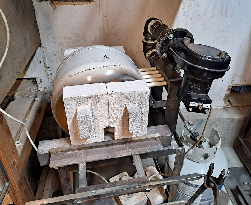
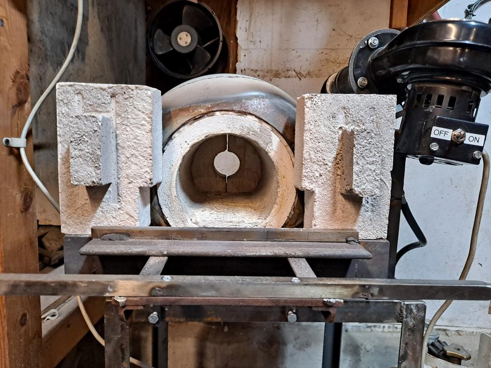
My old forge was starting to fall apart so it gave me the opportunity to build a new one with an idea I'd been thinking about. Nothing particularly different in concept here except the "ribbon burner" part. Instead of a cast burner I used 5 ceramic tubes. They are 3/8" ID, and 1/2" OD. Good up to 3k degrees F. These are more than sufficient to provide as much heat as I need. I used a small propane tank for the outer shell. The combustion area is 1" thick Kast-o-lite which is 5.25" in diameter by 9" long. This size is ideal for the type of work I do. I cast some doors for the front and back. The back doors have an exhaust port and can be opened for long pieces. The doors are all 2" thick and also made from Kast-o-lite. My goal was to make an energy efficient, well insulated forge where the majority of combustion takes place inside the forge and the resulting heat is retained. This forge achieves those goals to a large extent while still being functional and flexible. I also made a video of the build for anyone who is interested: https://www.youtube.com/watch?v=67Yl7_g3KO4&t=15s
-
Holding up just fine.
-
Mechanical to Pneumatic hammer conversion
Ted Ewert replied to Ted Ewert's topic in Power Hammers, Treadle Hammers, Olivers
I made a few more modifications, namely to make it easier to switch between one shot mode and repetitive mode. All the control is now attached to the treadle. One shot - repeat.mp4 -
Mechanical to Pneumatic hammer conversion
Ted Ewert replied to Ted Ewert's topic in Power Hammers, Treadle Hammers, Olivers
I have the first version done. The timer has worked as expected and provides a variety of operational modes. As you can see it has a dial to vary the speed of oscillation. The numbers represent multipliers of the selectable unit at the bottom, in this case .1 second. This makes it easy to adjust the speed of oscillation for your particular needs. The timer has 4 modes, two of which I find useful. It has a one shot mode for a single firing of the cylinder. The ram is held up until the start button is pushed. The cylinder is then activated for one cycle, at the rate set on the dial. The other mode is called the flicker mode. This is a continual cycle mode which can be halted and restarted by the reset button. I have added a switch on my flow control valve which shuts off the cycle when the treadle is released. The ram then defaults to the up position and is held there until the treadle is depressed. This saves air between operations. This is a picture of the valve and the switch. I cobbled together a mount for the valve, which is epoxied in place, which works well. I built the control box as an experimental platform to explore how this timer works. It could certainly be condensed into a smaller package. Here's a pic of the hammer as it stands: The cylinder is attached to the ram guide and bolted to the ram. I still have to cut off the roller assembly. That's it in a nutshell. The hammer now hits a lot harder than it did before, as well as being more versatile and controllable. This simple conversion can be done on almost any type of mechanical hammer. The videos I posted above show some of the construction and early testing if you're interested. -
I was going to build a whole new hammer, but I decided to convert my mechanical hammer instead. I'm using a timer relay and a solenoid valve to control the hammer. It's actually a pretty simple setup and a flexible way to accomplish what I need. I've been working on this project for the last month or so, trying to learn about pneumatic parts and how they all work together. I knew very little before I started, but found it interesting once the picture became a bit clearer. What I came up with is basic enough to convert most mechanical hammers to pneumatic. I started off by stripping the hammer down to bare bones. I removed the motor and mounts, as well as the cam mounts and the rocker arm assembly. I reinforced the center column since it was going to be taking on a large off-center load. I then started adding components. I made a couple of videos of the process. I'm learning to edit so they're a little rough around the edges. I spent over 30 years working at a TV station, much of it spent repairing editing equipment, but I never actually learned how to do it. It's kinda fun. https://youtu.be/wDuEiDpRFHk https://youtu.be/gJhNIRmLvcE
-
What did you do in the shop today?
Ted Ewert replied to Mark Ling's topic in Blacksmithing, General Discussion
Anyone with a little experience can knock out a decent hook or bottle opener. What I see in your work, along with other talented blacksmiths, is a quality of precision and symmetry which only comes with years of practice. I've had enough difficulty to appreciate the higher levels of craftsmanship. The cutoff tool you made is a good example. When I first saw it I thought: WOW. The shank is centered and square to the flat bottom. The shoulders are the same height, and even all the way across. The tapers up to the edge are even, smooth, square and the same on both sides. All the proportions work. That's very impressive to me. Torbjörn Åhman is another smith I marvel at. He has that same stubborn drive to to do it right, no matter how many times it takes. That level of "good enough" is way above me. -
What did you do in the shop today?
Ted Ewert replied to Mark Ling's topic in Blacksmithing, General Discussion
You could make a bottle opener with a feather on the end and kill two birds with one stone. Or not. -
What did you do in the shop today?
Ted Ewert replied to Mark Ling's topic in Blacksmithing, General Discussion
Just decorative. They show up better with a black finish, but I decided on a clear coat instead. Thanks Rojo! -
What did you do in the shop today?
Ted Ewert replied to Mark Ling's topic in Blacksmithing, General Discussion
Nice axe Benona. All I've made recently is some hooks for folks who requested them. I've also been practicing making feathers. I am once again rebuilding the power hammer, which has taken up most of my time. I'm converting it from mechanical to pneumatic. I'll post it when it's done. -
What did you do in the shop today?
Ted Ewert replied to Mark Ling's topic in Blacksmithing, General Discussion
My hat's off to you Jennifer. Your combination of talent, desire and work ethic is obvious in the pieces you produce. Watch out though, I'm retiring in a few years may catch up by the time I'm 90. -
What did you do in the shop today?
Ted Ewert replied to Mark Ling's topic in Blacksmithing, General Discussion
Beautiful hardie tool Jennifer. Don't think I could swing any hammer for 5 hours, let alone a 6 pounder. That's what a desk job will do to you. -
Power hammer build
Ted Ewert replied to Ted Ewert's topic in Power Hammers, Treadle Hammers, Olivers
I'm actually building a design by Joshua De Lisle. It's a very simple hammer, but just what I want. https://www.youtube.com/watch?v=hfJFDZTZTqc I'm in the process of collecting materials. There is a construction site close to my work with a large dumpster marked "metal only". I talked to the foreman and he told me to take all I want. Golden words! It may take a while, but as soon as I get all the pieces I'll stat a new build thread. -
Power hammer build
Ted Ewert replied to Ted Ewert's topic in Power Hammers, Treadle Hammers, Olivers
I thought about it, maybe if a few people are interested I will. I just get tired of the negative comments here when I don't build things the conventional way. I'd love to if I ever get up your way. Thanks -
Power hammer build
Ted Ewert replied to Ted Ewert's topic in Power Hammers, Treadle Hammers, Olivers
Thanks KS, glad you like it. I didn't know anything about power hammers before I built it either. My method of learning is to build one, and by the end I know exactly how they work. I have a pneumatic build just starting. Mechanical hammers move plenty of metal, but air hammers have so much more control. I think a VFD is a waste of money. A decent clutch will do the same job, for a lot less money. -
When you turn your air flow down you'll start to get burnback through your burner. This is because your flame front exceeds the velocity of the gas exiting the hole. I have found that most ribbon burners have way too many holes for efficient operation. I run mine on six holes and it gets as hot as I want with no problems whatsoever. Plug up about a third of your holes with Kaowool and see if the problem goes away.
-
It will only backfire if the rate of burn (flame front) exceeds the exit velocity of the gas. An easy fix is to plug up a few of your burner outlets with some wool. That should increase the gas velocity through the other ports.
-
Power hammer build
Ted Ewert replied to Ted Ewert's topic in Power Hammers, Treadle Hammers, Olivers
"So it only has one speed?" No, it has two speeds: on and off. If I wanted to vary the speed I'd have to get a VFD or a pneumatic drive system. It's simply a proof of concept for a possible alternative to a clutch. "I'm not see much snap to it either." If you watch the drive rollers in the video, you'll notice that they only extend about half way up the lever. I wasn't running it full tilt. I was running it at the amount of impact I wanted at that time, which is the whole point of the mechanism. I can now feather the drive so I get a nice point on a taper instead of a squished mess, or I can run it hard to move a lot of metal. I have a whole lot more control than with that lousy clutch I had. I consider it an improvement. -
Power hammer build
Ted Ewert replied to Ted Ewert's topic in Power Hammers, Treadle Hammers, Olivers
In an effort to get some more control of the hammer, I decided to try something a little different. A V belt is not made to slip, and makes a lousy clutch. A flat belt would work better, but it's still a clutch. I figured that varying the distance of the drive linkage to the fulcrum might be an option since that will change the distance that the hammer travels. I tried a number of configurations that didn't work well, but finally got something to work pretty good. It aint perfect, but it does vary the amount of impact on the work. I built a sliding roller which pulls the linkage in towards the fulcrum to increase the travel of the hammer. This works against a spring which returns the linkage (upon the release of the foot lever) to a spot out on the lever where the hammer oscillates without making contact with the anvil. This is the "neutral" position This is the engaged position The roller is screwed into a piece of 1 X 1 solid bar stock, which slides through the 1 1/4" tubing. Steel cable is attached to the end of it and run down to the foot pedal. I got rid of the spring rocker and used a solid piece of 1/2" X 2.5" steel instead. I built a spring into the hammer to take any excessive shock load off the drive train. And because I know someone would want to see a video, I made one of those too... -
Power hammer build
Ted Ewert replied to Ted Ewert's topic in Power Hammers, Treadle Hammers, Olivers
I'm only a couple of miles from the ocean, which provides natural air conditioning for most of the summer. It also chases the magic winter dust away. The down side is that none of my kids can afford to live where they grew up. -
Power hammer build
Ted Ewert replied to Ted Ewert's topic in Power Hammers, Treadle Hammers, Olivers
I've heard of that stuff. I see it in pictures along with Santa Clause. Must be left over from Christmas. -
Power hammer build
Ted Ewert replied to Ted Ewert's topic in Power Hammers, Treadle Hammers, Olivers
Nice hammers! That's a big ol' piece of steel you have there. My back hurts just thinking about trying to move it. What's all that white stuff on the ground? -
Power hammer build
Ted Ewert replied to Ted Ewert's topic in Power Hammers, Treadle Hammers, Olivers
I'd like to see your hammer, and that block of steel. You must have some heavy equipment, or a hoist, to move that stuff around. All I have is a hand truck a three strong sons (if I can rope one in) to help me move my equipment. I also need more space. I had to shoehorn this hammer into a small area close to the forge, which makes it hard to work on. I'll be retiring in a couple of years and would like to buy a property with a separate shop, or the room to build one. I need a place that I can make some noise without the neighbors or the wife complaining about it. All theory aside, the hammer I built is more than adequate for the stuff I make. It's a great time saver for drawing out tapers or flattening thick stock. It's a decent hobby hammer. A lot of guys are in the same boat I'm in; limited space and limited access to heavy materials and the machinery to work it. I'm hoping this thread gives those guys some ideas on how they can also build a moderate hammer to fit their needs and budget.
