

Ted Ewert
-
Posts
557 -
Joined
-
Last visited
Content Type
Profiles
Forums
Articles
Gallery
Downloads
Events
Everything posted by Ted Ewert
-
Power hammer build
Ted Ewert replied to Ted Ewert's topic in Power Hammers, Treadle Hammers, Olivers
A lot of people here seem to be stuck on the idea that a large mass is the best or only way to attach an anvil. It does work just fine, but it is not the only effective way to mount an anvil. Keep in mind that the only thing a large mass does is to reduce vertical displacement of the anvil. That's it. The reduction of vertical displacement can also be accomplished in a number of other ways. Take for example using a large base area. More area on the base will reduce the PSI across the surface, thereby reducing the amount of compression on the floor. This would work well on a dirt floor. A solid column buried deep in the ground will also provide ample stiffness. The depth would depend on soil conditions. A 6 or 8 inch pipe, filled with concrete and capped with a 3/4" or 1" thick plate would make a nice stand. I pounded in nine 5/8" rods below my anvil today and stiffened it up considerably. I didn't hit the hard rock I was hoping for (which seems to be everywhere else on the property where I try to dig a hole), but I did hit some good solid earth. We'll see how it holds up over time. -
Power hammer build
Ted Ewert replied to Ted Ewert's topic in Power Hammers, Treadle Hammers, Olivers
I wanted to clarify what the difference in power distribution is between a crank and a cam. The following wave forms roughly represent the comparative linear velocities imparted to the hammer by each device: The blue line represents a crank The black line represents a double action cam This chart represents 360 degrees of rotation. The vertical axis represents linear velocity, horizontal axis is degrees of rotation. We'll say that the 180 degree mark represents the point of impact of the hammer. As you can see, the maximum linear velocity the crank imparts occurs at 90 degrees. At that time the velocity decreases to zero at the point of impact. This slowing is also acting as a drag on the hammer. On the other hand, the cam continues to increase the velocity of the hammer up to the point of impact. This significantly increases the energy imparted to the work, and also increases the efficiency of the hammer. The cam is similar to a pneumatic hammer in this regard. The crank imparts zero linear velocity at the point of impact while the cam is at its maximum velocity. This is the key difference between the two. The cam also reflects a much smoother load on the drive train, allowing better clutch performance and reducing wear. I have heard that people are generally disappointed with the performance of their hammers when using a VFD. I would speculate that the crank is a major contributor to the lack of performance. I think a cam would work much better. The design of the whole drive train can be simplified with a cam, since it needs far less spring to store and release energy than a crank does. That could be a separate thread in itself. I hope this information has been helpful, as I have found the cam to be a major improvement over the crank.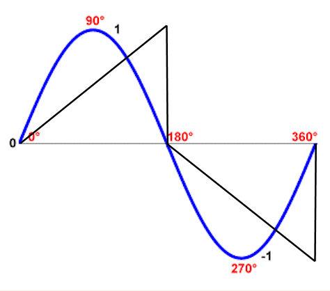
-
Power hammer build
Ted Ewert replied to Ted Ewert's topic in Power Hammers, Treadle Hammers, Olivers
It's about 100 lbs. Buzzkill is correct as the concrete bares no load. David. I currently have a rubber mat under the anvil. The problem is that the slab acts like a trampoline. It's sitting on sand, which gives enough to allow deflection. As with your presses, I need to isolate the shock. The rock can't be more than a foot below the slab. I tried to drive a grounding rod in just outside the garage and only got down about 6 inches before it stopped cold. I'm going to try the pilings tomorrow and see what happens. If that doesn't work I'll start digging. -
Power hammer build
Ted Ewert replied to Ted Ewert's topic in Power Hammers, Treadle Hammers, Olivers
I agree. If you're on soft dirt, a large mass above grade may be the best option. All we're really trying do here is to minimize vertical displacement. However that's accomplished is dependent on the individual circumstances and preferences. I've been toying with the idea of drilling holes in the slab below my anvil and driving steel rods down to the bedrock. I would then grind them to within an eighth of an inch of the slab, and mount the anvil on those. Maybe 6-8 "pilings" would be enough. I might try it just to see if it works. -
Power hammer build
Ted Ewert replied to Ted Ewert's topic in Power Hammers, Treadle Hammers, Olivers
No. My anvil is working just fine. The concrete slab is what's giving me problems. The slab is what's transferring the shock to the rest of the house. If I disconnect the shock from the slab it won't do that anymore. Why in the world would I want to spend the money to by 1400 lbs of steel, let alone try and move it, when I can tie into millions of lbs of bedrock with a moderate amount of concrete and rebar? The anvil and concrete will nicely transfer all the shock load into the bedrock, which is not going anywhere. It will also recover some of the wasted energy you pointed out. Nothing wrong with making the anvil massive if that's what you want, but it's not always necessary. I only have a 35 lb hammer, which is not particularly large. I don't think it's going to be too much trouble in my case to significantly reduce the vibration. I recently watched a video (all in German) where they changed out an anvil base for a water powered hammer (very old school). The base was a tree trunk, maybe 4 feet in diameter and about 6 feet long. They dug out the old one and had a hole about 5 feet deep. They positioned the new base and packed soil around it. Not only is this a solid base, but it transfers the shock deep into the earth. The shockwave is travelling downward, so the deeper you make the hole the less likely it is that any of the energy is going to come back to the surface. -
Spring loaded hand hammer
Ted Ewert replied to larrynjr's topic in Power Hammers, Treadle Hammers, Olivers
If it works for what you need it for, congrats! Nice build too. I'd have to agree with JHCC's suggestion of a treadle though. It would be easy to build, and you could get a lot more bang while freeing up an extra hand. As for the "criticism", you have to expect it if you're building anything a little different. Take it for what it's worth, but don't take it personally. -
Power hammer build
Ted Ewert replied to Ted Ewert's topic in Power Hammers, Treadle Hammers, Olivers
You're probably right that I won't be able to completely isolate the vibration, but some is better than none. I've got bedrock under the slab, so I'm hoping that large mass might not transmit as much of a shock wave as packed soil would. Who knows. I would like to eventually build a pnumatic hammer, but I'm still in the infant stage of the power hammer world. I have to say that it's a lot of fun to use, and a big time saver. I still have to build some more dies. My next one will be a fuller. I'd also like to build some sort of quick change mechanism for the dies, but haven't figured that one out yet. -
Power hammer build
Ted Ewert replied to Ted Ewert's topic in Power Hammers, Treadle Hammers, Olivers
I've been practicing a bit on the hammer. I figured simple tapers were a good place to start so I made some hooks. The closest hook was made from 5/8" square stock, and the hammer made short work of flattening out the finial. I actually shortened the hammer stroke for the smaller stuff because I don't have fine control of the stroke and it was over squishing the thinner parts. The "clutch" is more of an on /off control. I saw a video where a guy was making feathers with 3/4" angle iron. I made a hardie tool with a slot in it for the raised portion, and it worked pretty good. I textured one and chiseled one, and the chiseled one took a whole lot longer. I like both styles. I beefed up the center column with some 3" angle iron. The outer edges of the angle fit perfectly on the "fins" of the I beam, so I welded it on one side and it's quite stiff now. Looks a bit odd but it did the trick. I also found out that bolts like to come loose unless tightened hard. The only thing which has worked flawlessly from the start is the anvil. I got a lot of grief over that design, but it has performed beyond my expectations. No deformation of the steel and no cracking or spalling in the concrete whatsoever. In fact, everything I have made with concrete (two anvil stands and a swage block) have never shown even the slightest failure of the concrete. Reinforced concrete is a whole lot tougher than people realize. Heck, they used it for bunkers and pill boxes back in the day and it held up well, even against artillery. The only other thing I should have done is to make an isolated pad for the anvil. When I run the hammer it shakes stuff off the shelves in the shop and you can hear and feel it all over the house. The wife isn't real happy about it. I may have to rent a concrete saw and dig out a good sized hole for a new pad. I think I'll be good if I can get the anvil separated from the slab.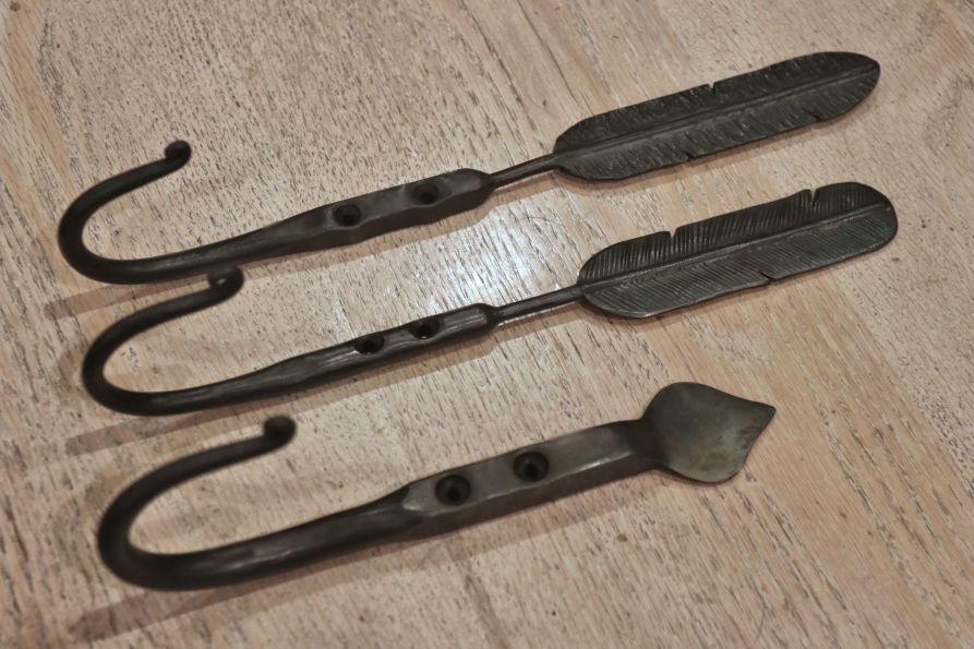
-
Power hammer build
Ted Ewert replied to Ted Ewert's topic in Power Hammers, Treadle Hammers, Olivers
Thanks guys, I appreciate the support. The vibration is due to small support column. If I did it again, I would use at least a 5 inch square tube. Scrounging is cheaper, but you pay the price in other ways. Since that video I have installed some support to minimize the movement. I don't know any way of stopping the thing with the hammer up Steve. It just stops wherever. It's not what you would consider a sophisticated piece of machinery. The speed reducer has a worm gear which doesn't lend itself to any slop. I'm sure there's some way to do it, but it's not that big a deal to me. I'm still trying to figure out how to use it properly. I plan on forging something with it tomorrow, so we'll see how it goes. -
Power hammer build
Ted Ewert replied to Ted Ewert's topic in Power Hammers, Treadle Hammers, Olivers
OK, I posted the video on YouTube: I'm curious if anyone now, or in the future, would want to try a drive system like this. A cam can be used in place of any crank, but there are a few things to take into account to make it work properly. I can post what I learned if anyone is serious about it. -
Power hammer build
Ted Ewert replied to Ted Ewert's topic in Power Hammers, Treadle Hammers, Olivers
It does hit harder, I noticed that right off the bat. I don't think it's whip as much as it is straight drive. It goes back to a crank slowing down (vertically) during the last 90 degrees of rotation, while a cam actually speeds up during this portion of the cycle. The cam assembly is a little more difficult to make than a crank, but it works a whole lot better. It doesn't shake the bolts loose either like the crank did. Just a note, you don't need a solid round to make a cam. You could use a steel ring with a vertical bar for the axle. I'll try uploading the vid to Imgur and attaching it that way to see if it works better for you guys. -
Power hammer build
Ted Ewert replied to Ted Ewert's topic in Power Hammers, Treadle Hammers, Olivers
Works for me, anyone else? Here are a couple of pics For the cam I'm using a 8" X 1" disc which I had from another project. I offset the hole 2.25" from center which gives me a total of 4.5" of travel. I'm also using 1" wide by 2" high nylon rollers. I was thinking that a cam might work better than a crank for those who are using a VFD. It's much smoother and doesn't have any slowdown in the cycle. -
Power hammer build
Ted Ewert replied to Ted Ewert's topic in Power Hammers, Treadle Hammers, Olivers
I mentioned earlier that I was going to try a cam instead of the crank, so I finally got that built. The reason I went to a cam is that a crank only accelerates the hammer for 90 degrees of rotation. The other 90 degrees is slowing down. With a cam I get full acceleration through 180 degrees of rotation. This cam is a double action cam where it drives the hammer both up and down. This is accomplished through having a roller above and below the cam, so when the cam is finished pushing in one direction it immediately starts in the opposite direction. To do this I have four rails, two on each side of the cam, which straddle the drive shaft and ride against bearings mounted right next to the cam. This arrangement allows the the cam to drive the rollers while also keeping the rollers constantly aligned in a vertical plane. Here's a short video I made for illustration... MVI_2637.MP4 -
Power hammer build
Ted Ewert replied to Ted Ewert's topic in Power Hammers, Treadle Hammers, Olivers
OK, I'll be happy to update any changes I make, and maybe even a video while I learn how to pound metal with it. Failure is only when things go south and you give up. The hammer learning to fly was a bit of an eye opener. Fortunately I was standing off to the side and out of range and no damage was done. That was the clincher for shortening the crank though. -
Power hammer build
Ted Ewert replied to Ted Ewert's topic in Power Hammers, Treadle Hammers, Olivers
I hope at least a few of you enjoyed this thread. I built this hammer not purely for my own benefit, but also to show guys who want to build one that it's not that difficult. I also built it for under a thousand dollars, which could be further reduced with some more creative scrounging. That's fairly cheap in the world of power hammers. It not the biggest, and certainly not the best, but it works and will adequately serve my modest needs. It will also save my aging arm a lot of wear and tear. Most importantly, it was fun to build. Learn to build Build to learn -
Power hammer build
Ted Ewert replied to Ted Ewert's topic in Power Hammers, Treadle Hammers, Olivers
Well, good for your hammer. -
Power hammer build
Ted Ewert replied to Ted Ewert's topic in Power Hammers, Treadle Hammers, Olivers
After pondering a cam system for a week or two, I decided to give the crank one last try. I ordered some larger diameter (6 in) pulleys which would fit a B size belt, and got a BX belt to match. This works far better than the little 4L belt I had before. Consequently, I found that my crank was too long for this particular configuration, and shortened it to roughly where it was before (2 1/4 in). This was due to the spring over flexing and pulling the hammer out of the guide and throwing it halfway across the room. These are the types of effects you just don't get on paper (or in a model). I had some trouble with the hammer sticking in the guide. The lateral force of the rollers wanting to slide off the end of the spring when it's bent is fairly high. This occurs during the first part of the lifting cycle. Having tight tolerances between the guide surfaces and the hammer minimizes the amount of cocking the hammer can achieve, but any little amount of friction can cause sticking. Since the material I'm using is resistant to oils, I sprayed some light grease on the surfaces and solved the problem. I had to clamp the springs together for added stiffness. It's not a proper floating spring clamp, but that will come later. Reversing the direction of 35 lbs of hammer takes a fair amount strength. Adjusting this clamp to the optimal position will still take some fiddling. I also modified and mounted a motor adjustment plate so I can adjust the motor position if the belt stretches. I think I can still get some more travel out of the hammer so I'll try that. Otherwise I'm pretty happy with the overall operation at this point. The hammer hits hard, and I think with the right dies, I may be able to shape some steel. The anvil is relatively quiet (no ringing) and has held up quite well. MVI_2561.MP4 MVI_2561.MP4 -
Power hammer build
Ted Ewert replied to Ted Ewert's topic in Power Hammers, Treadle Hammers, Olivers
I've decided that the crank, pulleys and clutch are not the most optimal mechanism for this application. I'm going to rebuild the whole drive system using a cam instead of a crank. I like the cam because it is a constant load through 98 percent of the cycle. I've mostly worked out a "clutch" mechanism, but it's still in the planning stage. Stay tuned... -
Power hammer build
Ted Ewert replied to Ted Ewert's topic in Power Hammers, Treadle Hammers, Olivers
My belt is so stretched that the hammer barely worked, but you can see the basic operation. This is why I was a little reluctant to post a video. The hammer needs some more work. MVI_2560.MP4 -
Power hammer build
Ted Ewert replied to Ted Ewert's topic in Power Hammers, Treadle Hammers, Olivers
The reason I hesitate is because I don't have it running the way I would like it to run. I can show you how it's running currently if you like. It smashes metal well enough, but it isn't smooth and efficient yet. The problem with a crank in this application is that it has widely varying loads throughout the cycle. This results in uneven clutch loads, which is why my clutch doesn't work well and possibly why the belt heats up. A flywheel is the most practical solution, which I plan to install on the crankshaft. My belt is also stretching, so I am going to make an adjustable motor mount. This will also be handy if I decide to change pulleys. -
Power hammer build
Ted Ewert replied to Ted Ewert's topic in Power Hammers, Treadle Hammers, Olivers
Maybe -
Power hammer build
Ted Ewert replied to Ted Ewert's topic in Power Hammers, Treadle Hammers, Olivers
TP: Yes, it's a slip belt clutch and I started smelling burnt rubber. I'm going to order new pulleys to speed up the BPM anyway, so I was also going to get a thicker belt size. I'm using a 4L currently and the clutch is anything but smooth. Maybe it's not sticking well enough or it's just undersized. The belt was too hot to touch. I don't have enough experience with this type of clutch to really know what's best. Maybe belt dressing, as Frosty suggests, is the answer. My gut just tells me it's too small. I did think of adding another spring and that may be the easiest option. I may also have a trampoline spring or two around. It's not a big issue anyway. Thanks all for the suggestions! -
Power hammer build
Ted Ewert replied to Ted Ewert's topic in Power Hammers, Treadle Hammers, Olivers
Well, I got it running. It smashes hot steel as expected, although a few changes are in order. You guys were right in saying it's a little slow and I'm going to remedy that with new pulleys. The belt and pulleys I have on it now are undersized anyway. The belt gets pretty hot after only a few minutes of use. Any suggestions? I also need a stronger spring to hold the foot petal up. All I could find locally was a screen door spring and it aint cutting it. Nevertheless, the hammer hits good and hard. I made a couple of flat dies for it out of 4140, which I hardened and tempered. They don't make a pretty mark in the metal but they do give me some idea of how it's working. I'll build some fuller dies next. Here's a few pics. Sorry for the clutter in the background, I had to move a lot of stuff around to shoehorn this in a corner next to the forge. Got it all bolted to the slab -
Power hammer build
Ted Ewert replied to Ted Ewert's topic in Power Hammers, Treadle Hammers, Olivers
I find designing mechanisms in my mind to be rather relaxing. It's my form of meditation. I'm hoping to get the electrical done today, then it will be time for a test run. I still have to build some dies for it too. -
Power hammer build
Ted Ewert replied to Ted Ewert's topic in Power Hammers, Treadle Hammers, Olivers
Got a little more work done on the hammer. I built the hammer guide and attached it. I also go the hammer finished, as you can see. I built it out of 1" solid square stock which I cut to 12", with the middle piece being used as the attachment rod. I welded a pre-drilled and tapped face plate on the end. This was made from 3/4" plate. I also added two 1/8" sheet metal pieces to the sides of the hammer for the primary wear surface. I made the roller assembly with a couple of nylon rollers. They seem to work pretty good. I have a piece of 4140 coming to make the dies out of. It's 1" thick by 2" wide by 12". I should get a few good dies out of that. I just have the foot control for the clutch to finish, and a few other odds and ends, and it will be ready to test.