Sanderson Iron
-
Posts
158 -
Joined
-
Last visited
Content Type
Profiles
Forums
Articles
Gallery
Downloads
Events
Everything posted by Sanderson Iron
-

Mechanical hammer brake adjustment
Sanderson Iron replied to beaudry's topic in Power Hammers, Treadle Hammers, Olivers
I didn't know the Beaudry was cast to cast too. Interesting. Where're you located, Willey? I'm in southern Michigan. I'd love to see your hammers too. -
Mechanical hammer brake adjustment
Sanderson Iron replied to beaudry's topic in Power Hammers, Treadle Hammers, Olivers
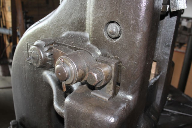
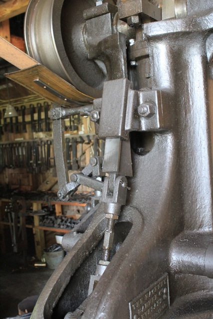
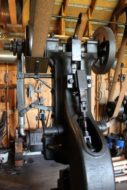
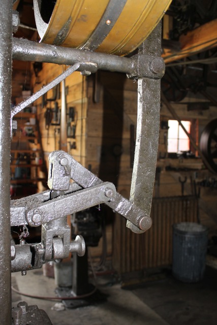
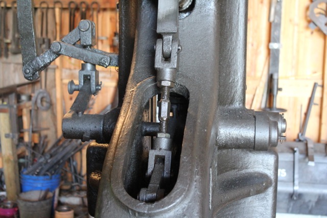
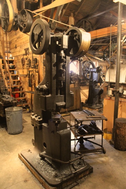
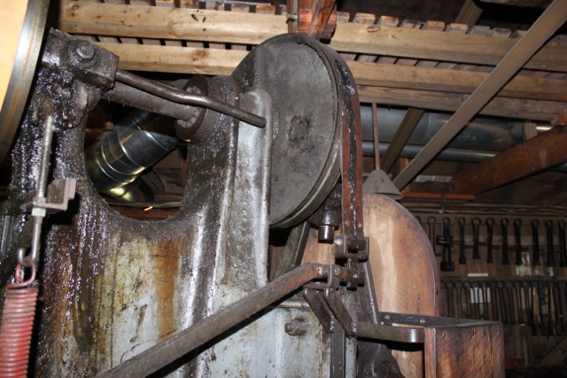
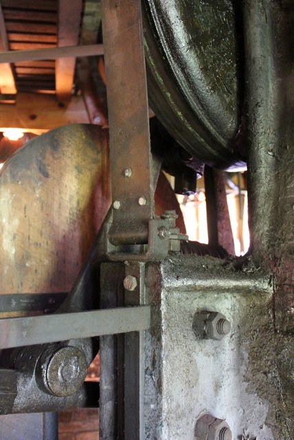
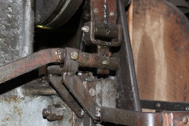
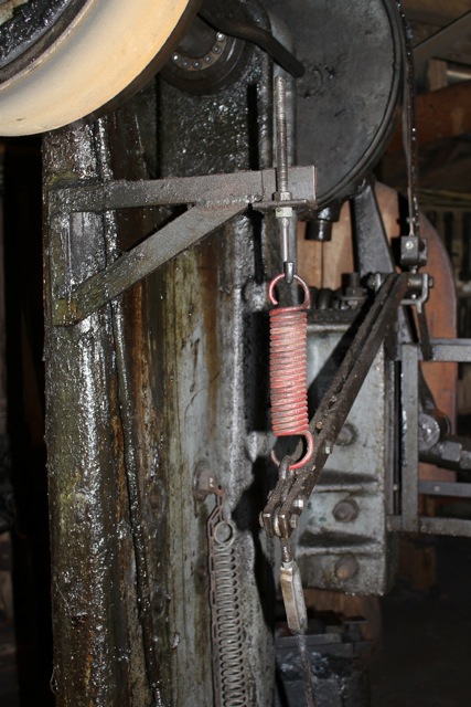
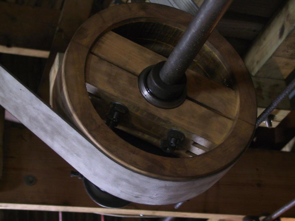
Mr. Willey, your hammers are just delicious. Wowsers. I want one. Nice shop too, by what I can see of it. (Drool drool) Here are pictures of my Hackney's brake and control system. This is a 100 pound hammer. There are three controls which happen simultaneously: the clutch, which controls the RPM; the brake, which stops and starts the ram; and the air valve, which controls the stiffness of the spring (the air cylinder). The standard on this model is hollow, with the links inside, but he anvil, just below the die, is solid. (The double standard Hackneys have solid standards and anvils.) Interesting, the Little Giant style hammers are opposite as far as I have seen, with a hollow anvil and a solid standard. The brake itself is pretty simple. The left hand ram guide (which is bronze) is in a slot with a wedge behind it. As the wedge is inserted, the guide moves over, locking the ram. This is a very positive lock. I can put a three foot board between the dies, lock the ram, and put my weight on the end of it without lifting the ram. This lets the ram be used to hold for upsetting, twisting, switching ends with the tongs and so on. I have to say though, when oil gets on the guides from above, the lock is less effective, so when I need to lock it securely, I squirt a little kerosene on the guides. Seems to work fine. There is a link connected to the wedge which has a gear thingy on the end that connects to another gear thingy which, when rotated… Oh fiddle, you can see how it works without my thingy definitions. It's the third picture. Here's how the air spring is adjusted: there's a plunger valve on the back of the air cylinder which controls how much air is released. The faster the hammer runs, the more air is retained, so the stiffer the spring. With a Little Giant style hammer, there can be times when the ram will flutter and not hit. That's because the spring is too stiff for the blow being struck. If the spring were lighter, that wouldn't happen. Well, the Hackney gets around that issue by having the spring get stiffer as it speeds up and lighter as it slows down. It never, ever, flutters, but it tends to have a deader blow, and it's difficult to get a light, fast blow like is so wonderful with most mechanicals. This hammer has amazing low end control though. The fourth picture shows the slide which adjusts the air control. I'm sorry it's not very clear. I should scan in the patent drawings, which are much more explanatory. I hope this isn't getting too wordy. Just skip over this gobble-dee-gook and look at the pictures if you'd rather. The fifth picture shows the links, though it's hard to make out for all the mess in the background. Sorry 'bout that. To the right is the brake, the upper middle is the air control, and the left shows the clutch links. This clutch is a cast-on-cast clutch, believe it or not--no leather or brake lining. It has a steeper cone than other clutches I've seen, so that's probably how it keeps from sticking. It has to be kept oiled, but then, so does a Little Giant. There's a turn buckle thingy (here we go again) that is the clutch's adjustment. So to answer your question about timing, Beaudry, I have it timed like this: first, the treadle unlocks the brake. This lets it fall on the work, but how fast it falls is still under the operator's control. I can set it down gently, or I can let it fall. This is really nice for straightening bars, pushing drifts, center punching and so on. But anyway, as the treadle is pushed, the clutch begins to engage, causing the air cylinder to lift the ram. As it speeds up, the spring gets tighter, and the blows get snappier. The brake will stop the ram anywhere in the stroke, more or less. There is no ram height adjustment on this hammer. It will hit high and low pretty much the same, but you cannot stack really tall tooling under it. To solve that issue, I go the other way, with a bolster die and other things. But this thread is supposed to be about brakes, not dies. Well, I'll toss one in. Okay, sorry for the book. That was ridiculous. If you have any questions, I'll try to answer them with fewer words. Joel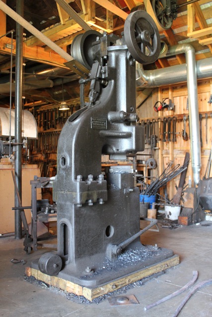
-
Mechanical hammer brake adjustment
Sanderson Iron replied to beaudry's topic in Power Hammers, Treadle Hammers, Olivers
I had taken some pictures, but they're not very good. I'll take some that are more clear when I'm back in the shop on Monday. I look forward to seeing the Beaudry pics. -
I really don't think a normal person can make or engineer the quality found in a Little Giant. A lot of people have tried. Pounding Out the Profits is full of them. You sure can't come close to it with three grand. You might also think about resale value. If you make a hammer and later decide you don't want it, will you be able to get what you need out of it? I'd be willing to bet you could sell that Little Giant in ten years for quite a bit more than it's worth now.
-
That kind of fire pot is an absolute curse. You'll be switching to gas in no time if you don't get something better. They are clinker makers, not clinker breakers. Throw the thing out. For thousands of years blacksmiths got along well without those things. And then along came the foundries...
-
What TYPE of power hammer is this
Sanderson Iron replied to FlyingXS's topic in Power Hammers, Treadle Hammers, Olivers
Apparently, for left handed blacksmiths. -
Mechanical hammer brake adjustment
Sanderson Iron replied to beaudry's topic in Power Hammers, Treadle Hammers, Olivers
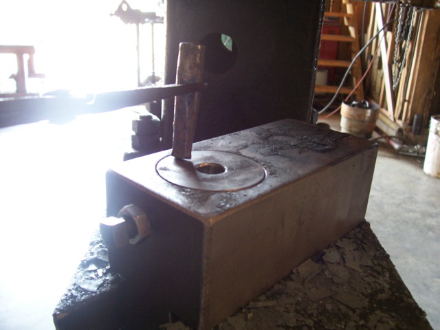
Here are some pictures of the brake I put on my 250 pound Murray. It works really well, with snappy starts and sudden stops, even on the down cycle. This hammer can hit hard, single blows, but when I hammer continuously, the brake doesn't heat up or wear that I can tell. I've never had to replace the leather on the band, and it's been there for 18 years. There's no difference between how it works on the first blow and how it works after an hour's run. It's adjusted so that it releases as I press the treadle, then the hammer starts, though the timing is pretty close. My Hackney's clutch releases much earlier so that I can slowly drop the ram and touch the work, then lift it and strike. That's a more complex system though and's built into the hammer. If anybody wants to see it, I'll show it in another post. On the Murray's clutch, there is a band, 1/8" by 3" which goes up and over the flywheel. This has a leather belt riveted to it with copper belt rivets. One side is anchored solidly, the other connects to a long arm which engages the brake. The pictures show how this better than I can explain it. One side, the side near the brake, is about 3 1/2" from the fulcrum; the other side, with the spring, is 38" from the fulcrum. That's quite a bit of leverage. There's a link just below the spring which connects to the treadle. The spring is quite stout. To get it tight, I threaded a rod with a hook on one end so I could draw it up. This spring also raises the treadle, so the original spring there had to be lightened. My 25 pound Little Giant doesn't have a brake. I've never felt it needed one. I use it mostly for swaging and straight-forward forging itty-bitty things, so that might be part of it; but with the lighter hammers, you can loosen the spring so the ram is more floppy, then you can get pretty close to single blows even without a brake, though they won't be as strong. I once worked in a shop with a 50 pounder which was essentially brakeless, and that's how I got it to do singles. I hope this was worth the read, Beaudry. Do you have it in your heart to show us some pictures of your brakes? Joel Post Script: I don't claim credit for this brake design. I think I saw it in an Anvils Ring in the early '90s or so. Can't remember.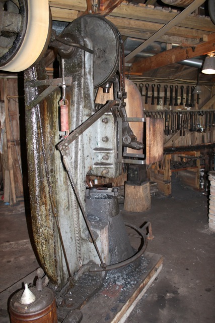
-
Unless you get really lucky on all your angles, each die needs it own key. At the very least, it'll need its own copper shim, which, I notice, you don't have in your picture. The angle between the ram and die won't be exactly the same in either length or height, so the copper compresses to make up the difference. I think my shims are 16 gauge, if I remember right. Might be 20. Keys are easy to make. The taper's generally 1/8" per foot. After you forge the key, tap it in loosely, pull it out, sand, grind or file the high spots, tap it back and repeat until it's touching its whole length as best you can. It'll wear in over time, as you drive it home over the years. I also heard Clifton Ralph talk about driving a key in hot and upsetting it to fit, but I've never done that myself. (At least I think it was him. Been awhile.) I'd do what Forgemaster says and shim the bottom over and make a new key--a metal shim with a strip of copper on one side, and your forged key on the other. Joel
-
Oh wow, Jim. That old one is perdy! I like it. I'm guessing the first one is digital? I thought there might be some new versions out there, but only old things stick to me somehow. Thank you for showing us.
-
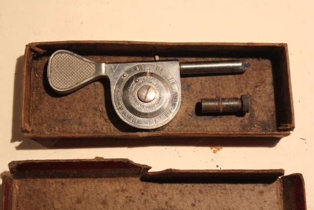
I suppose everyone here knows about speed indicators, but just in case, here are three different kinds. The first pictured is a Starrett, the second, a Jaquet and the third is a Hasler. Each one is held against the end of the shaft to show the speed the shaft is turning. With shafts that have a center hole, the metal point is held in the hole; if there is no hole, a rubber foot is put over the point, and that is held to the shaft. The Hasler and Jaquet also have rubber wheels for holding against the side of a shaft where the end is not accessible. This measures the feet per minute. The Starret indicator is common and can be picked up for very little money. Each revolution of the dial is 100 revolutions of the point. You hold it against the shaft and look at your watch, count the revolutions the dial makes, then remove the indicator from the shaft and read the dial, adding the reading to the number of revolutions you counted. It's best to have someone else look at their watch while you hold the indicator, especially if you're balancing on a wobbly step ladder. The Jaquet has two dials: one is a stop watch, the other the speed indicator. There are three dials reading 1,000, 100 and 1 revolutions. It is held to the shaft, and a trigger releases the mechanism to begin counting. It's very easy to use alone. The Hasler is the simplest to use. These come in high and low speed. This is a high speed. With these, there are two buttons; one returns the dial to zero; the other starts the movement. Just hold the point to the shaft, release the second button, and the arm moves until it reaches the speed of the shaft and then quits, even as you continue holding it. It is very simple to read. These are fairly common on Ebay.


-
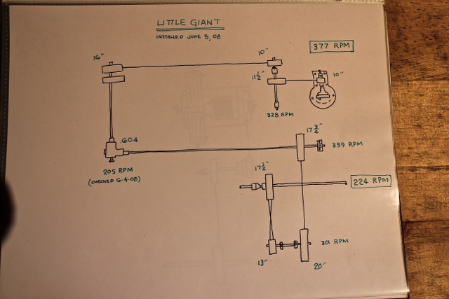
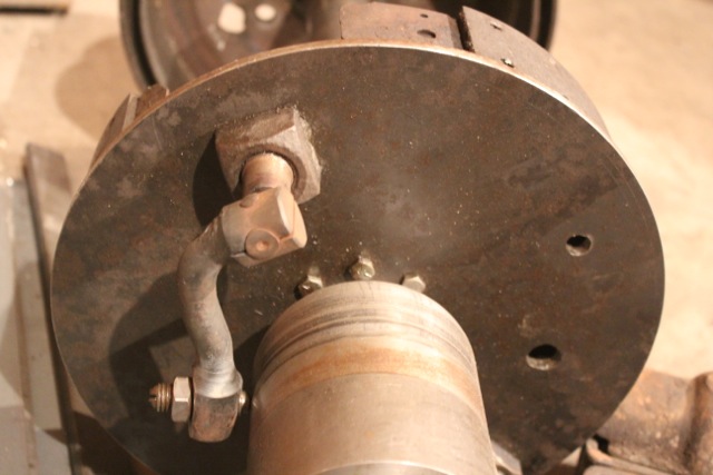
Here is something which I think is very important for a line shaft. It might seem kinda nerdy and unnecessary, but it has proven invaluable to me; and that is keeping a book of maps of all the machines and their accompanying countershafts and belts, showing each shaft's speed and usually each belt's horsepower. I call these Line Shaft Maps. My book is a ring binder. If I want to tie into a countershaft, I can look up its speed easily without climbing around with a speed indicator or redoing all the math of the pulleys. (In the second and third pictures, you can see where I connected the Little GIant to the press's third shaft.) If I want to know how fast a machine is running (let's say a grinder, for replacing a stone) I can just look it up. By showing the belts' horsepower, if a belt is slipping I can figure out which one is underpowered. Where there are gear boxes, I indicate the ratio on the map as well. I have a map for every machine in the shop. Of course, any machine with a cone pulley or different gears (lathe, mills etc.) has a tag nearby showing each speed. Joel


-
Did I say "overtime?" What a dork. Like I have a timed job or something. I think it'd be "extra time" or "too much time." Whatever. Here's another clutch I made. This is the one I made from a drum brake out of a pickup. Hopefully these pictures will give ideas to someone who might need to make one. The first picture shows the clutch assembled, less the pulley, which will fit to the right of the drum. There's a bronze bearing pressed into it. (Mistake, but I did it years ago.) On the left side is the cone which moves the arm to engage the shoes inside. This arm is visible in the second picture. The cone needs to spin freely on the shaft so that the arm and cone move together once engaged. There will be a yoke in the groove on the cone which will connect to the handle (no picture) to engage it. The last picture shows the inside with the brake shoes pivoted on the bottom. The arm in the second picture connects to a short shaft which rotates, spreading the shoes by means of the short S-shaped parts on top. The hub in the center is really too small for this size shaft, but I adapted it from its original position which was on a smaller shaft. I think it'll work. We'll see. It also still needs to be faced, to remove that sharp projection at its bore. Like I said earlier, I don't think I saved much by starting with a brake. It was just as simple making one from scratch. Joel


-
Thank you, Black Frog. I had fun that day too. I hope you come back some time. Of course you may post anything you want. (Well, good things anyway. ) I wanted to show a video I have on U-tube showing my wife making arches on the shaper, since it has shots of the overhead drive, hot iron and everything, but as soon as I pasted the link here, it tried to fill the window. I'm guessing it was trying to load it. Dunno though. Anyway, if you know how to do it, please tell me so that I can put that video up too. It's called Working Hot Metal with a Shaper or something like that. And thank you, too, Coyote Gear. I appreciate the compliment. It's just a shop though. Line shafts used to be common, and this is nothing compared to what was. Sad, really, to think that's gone now. I'm sorry I haven't done more on this lately, everybody. I've been meaning to post more pictures of clutches I've made, but I had a job come in the shop that had to have a lot of overtime, so I wasn't able to type as much as otherwise. It's finished and on its way to California now tho, so I should be back on this soon. Joel
-
I cannot seem to lay my hands on the information to answer this, Aplater. Somewhere, in an old book I have a formula telling the power of a press based on its flywheel size and another based on its shaft size. I don't know why I can't find it. I'll keep looking for you. The thing is, that won't answer your question on a practical level anyway, because you don't know how much power it takes to move hot iron anyway, and there are few sources to answer that for you. Basically, you have to experiment and do some testing, like you said. If you start with really open dies (like fullers, lining tools and whatnot) you'll get a feel for it so you can move on from there.
-
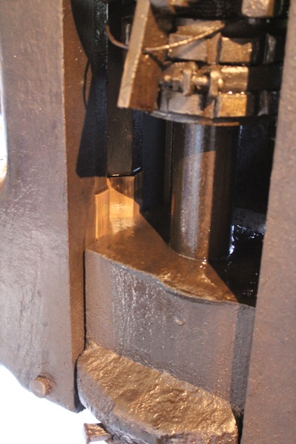
If I may say so Adam, it's an OBI (Open Back Incline), or your Mayer is a trip hammer. Sometimes a name can limit how you perceive it. One nice feature on that type of press is that there is a decent hole through the table beneath the ram. You can work through it from either direction--for catching drops, for bending through from above or for working longer bars from below. Let's say you want to make a long bolt, so you forge a ball and then draw the shank down to a third the diameter. You can pass it up through the table of the press, clamp the ball in a holder and upset it with any impression you can imagine. Each head will be the same, because you have already established the volume with your ball and your press will always make the same stroke and return without drifting to the side. That's tougher with my press, because the table is different. Plus, the OBI tilts so you don't have to work vertically if you don't want to. Now how long can your bar be? It can come all the way to my house if you want it to. Try that trick with a hammer; you can (and I have) with a bridge, but it's a lot more awkward and not nearly as consistent. I recently received an email with pictures of the Ford factory in 1916. In the press room there is an OBI running off the line shaft. These things go back a ways. Those are some nice clutches in that shop. It'd be well worth buying them if you can. Do you know what machine the two-step cone went to? Is it still there? I paid $2200 for it in 1999, which probably was too much. I thought it was in better condition. As it turned out, I had to have the crank ground, and I had to pour all new bearings, grind the valve and so on. But it had the governor with it, which is missing on the bulk of Reids. I needed that, of course. It's been a very good engine since I rebuilt it properly and learned its quirks. It also has more than enough power for anything I can put on it. Yesterday my wife was running the universal grinder all day while simultaneously keeping the Rockford drilling 1 5/64" holes; at the same time I was running the sheer and the shaper, which was making 1/4" cuts 14" long (for six hours straight); on top of that, the dynamo was generating 25 amps. That's five machines, and it didn't even care. It kept us warm besides. The drive belt stretches a little more and the lights have a wee bit more flicker is all you can tell when she's pulling a steady load. 750 cubic inches takes life seriously. Joel
-
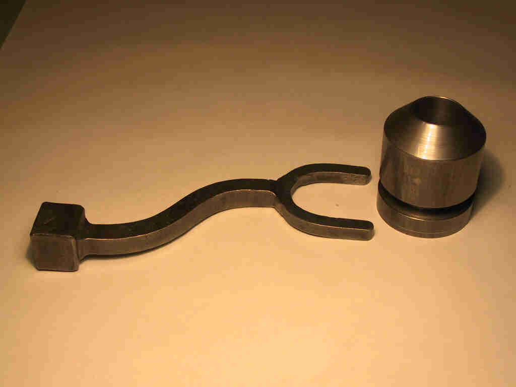
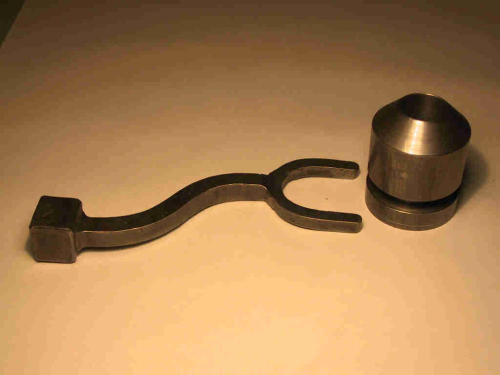
I've made four clutches. The first one was built from a brake out of a pickup truck. Then I made a dog clutch, because I thought it would be simpler (but it wasn't). The last two clutches I made were shoe clutches, made from scratch, which proved to be less trouble than trying to build one out of a brake. When a good line shaft clutch is disengaged, no surfaces rub other than the bearing on the shaft. An automotive clutch with its discs inside cannot be left disengaged forever or the discs will rub themselves thin and fail, not to mention this rubbing adds unwanted friction. One common type of line shaft clutch is a shoe clutch, or drum clutch. Usually the shoe is cast iron, a ring, which is spread apart by an arm so it expands against the inside of a drum. Most of the lathe clutches are of this type, and you'll sometimes see them in pairs, as I mentioned earlier, for forward and reverse (or in the case of my mill, high and low range). These are pictures of a clutch I made in 1999 for my horizontal mill. The shoes are maple. The drum (not pictured except in the last photo) is screwed to a plate which is mounted to a thick-walled pipe with pressed bronze bearings to fit the countershaft. (No close ups--sorry.) In this clutch, the shoes are engaged by two arms (see third picture), one for each shoe, which are moved apart when a cone is slid forward by the fork in the forth picture. The fork is forged form 1 1/2" square with a 3/4" square shank and 1/2" square forks (no welds of course). The arms are forged from 1" round with a ball on each end, and then drawn and swaged to 1/2" round between the balls. The ball joining the rocker attached to the shoe lever is 1" and has a 7/16" square broached hole which fits the square end on the rocker. This rocker is threaded above the square to secure the arm with a nut (visible in the third picture). The other smaller ball is tapped for the long screw which adjusts the clutch for wear. I think you can figure out the rest by the pictures. This clutch is about 10" in diameter. I made two--identical. One thing to note is the arrangement of the set screws. Two set screws at 30º is the strongest arrangement. This position offers more power than two set screws inline along the shaft. So any time you need to hold by set screw only (no key) 30º is the way to go. If anybody has any questions about these, I'll try to explain them more. Too much writing in one post already though. Joel Sanderson


-
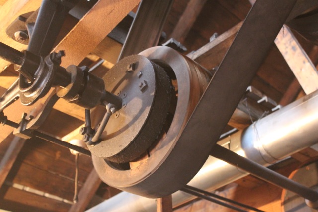
I just got an email from my father-in-law showing the progress he's making on the new pulley. This pulley is not going to be split. Instead it will have a steel plate in its center which will attach to a hub bored and keyed to fit over the clutch above the engine. (I'll show a picture when it's done.) The plate will fit inside the larger diameter and will be screwed to the smaller, which is the lower layer in the photo below.
-
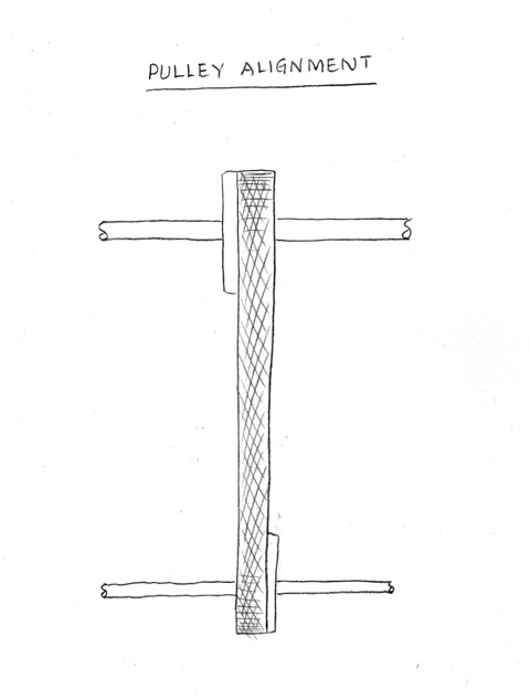
Sorry it took me so long to answer you. Been busy. The only pulleys that shouldn't have a crown are the ones which are opposite a tight and loose pulley. That is so the belt can move across the pulley as it is shifted from one to the other. Otherwise a pulley should have a crown. A crown keeps the belt in the center of the pulley because the larger diameter at the crown is doing more work, pulling more belt, than the edges are doing. Imagine if you had two ropes tied to a log at the other end of the yard, and you pulled one rope and your lazy neighbor pulled the other rope more slowly than you; pretty soon the log would be following along behind you and not your lazy neighbor. That's what happens with a crowned pulley too. If you have an 1/8" crown on a 30" diameter pulley turning at 200 RPM, the crown is pulling 6.5 feet more belt per minute than the rim is pulling. That's something, isn't it? Unless you understand why a belt centers on a crown, like I just explained, it would seem like a belt would want to climb to the high side when two shafts are not in line, but it does not. In fact, a belt falls off the close side. In the first sketch below, I have drawn a pair of shafts and pulleys on which the belt is riding to the right, in the direction of the arrow at the bottom. This indicates that the shafts are closer on the right (B) than the left (A). If you move the countershaft farther away on the right, the belt will track in the center of both pulleys. In the next image I have sketched a pair of pulleys where the belt is riding to the right on one pulley and to the left on the other. This indicates that the pulleys are the ones which are not in line, not the shaft. If you slide them towards each other on the shaft, the belt will track properly. Shafts are never perfectly in line. If you could have a pair in perfect parallel, there would be no need for a crown at all, but that's not how things work. The belt stretches and makes up for the imperfections in the alignment. (Which is a good reason to use new belts.) The longer the belt, the more forgiving it is, because it has more stretch. This means that two shafts close together are more trouble to align, so if you have a choice, belt your pulley to a distant shaft rather than to a close one. I did that with my shaper. I could have belted it just four feet away, off the first line, but instead I belted it across the room to the north line so I'd have a longer belt that would give less trouble. Anybody interested in some clutches I made, or is this getting too nitty-gritty? Joel

-
I was in Mexico and drove past a blacksmith working in his shop. No walls, just a roof on poles, dirt floor, an anvil, some old iron and a buzz box. Made me feel rich. Do what you can do, and help it grow. Don't go into debt over a dream, because you'll be paying interest on that dream instead of paying into the dream. Your business will need all the money it can get, so don't give it to a bank.
-
Okay, a warm tent. A yurt.
-
Forget the house. Build the shop. Live in a tent, then the other end of the shop. That'll clear up a lot of things in a year. Businesses build houses, not the other way around.
-
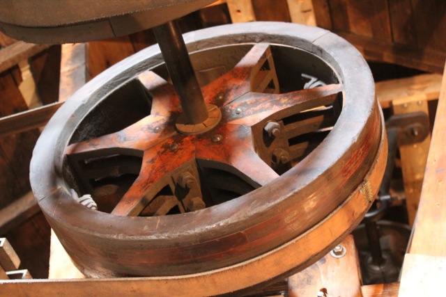
Cone pulleys are commonly missing from machines, since too often at some point some smart person decided to toss the cone pulley in favor of an electric motor and a gearbox or some other heinous contraption. It's a shame that happens so much. Cones are always in pairs, each one meant to be part of the machine, and their dimensions are critical, more so than first meets the eye. Cones of more than two or three steps are not composed of equal steps. For example, if the first step has an 8" diameter, the other steps might seem to be two inches larger, measuring 10", 12", 14" and 16". But this is not true. If a belt is put on a cone with equally different steps, the belt will be loose on the center steps and tight on the ends. Therefore, it is necessary to make the center steps of slightly larger diameters. There are different formula to figure this. The Complete Practical Machinist by Rose (1894) gives one formula, and the Machinery Handbook gives another slightly more precise formula. I'm saying this so that if anyone reading this makes a cone pulley, be sure to do the math to figure out the final dimensions, or you may be disappointed. Again, we made the cone pulleys out of maple. The wood is screwed to steel plates with hubs on the ends to fasten to the shaft. On the lathe's cone, the smallest diameter step is steel and serves as that end's hub; its outside diameter was turned last, along with the other steps' diameters. It's fastened to a plate and screwed to the wood as on the other end. I have never had a problem with these pulleys. However, I will say that dressing tends to build up on wooden pulleys while it doesn't on metal ones. The first four images show the five-step cone for the lathe; the remaining images show the three-step cone for the mill.


-
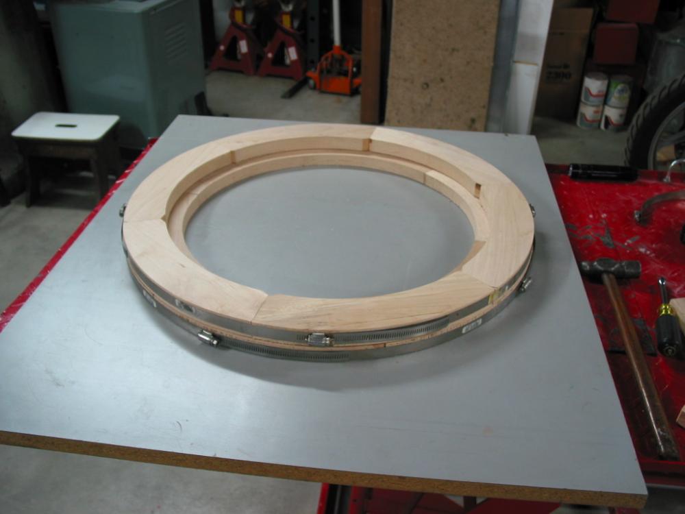
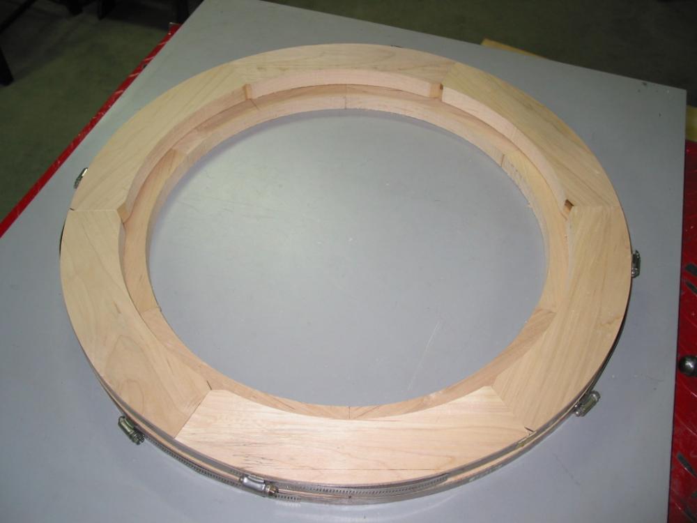
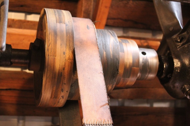
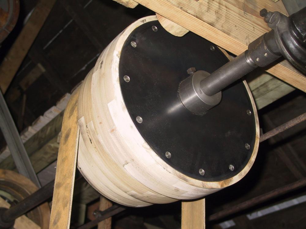
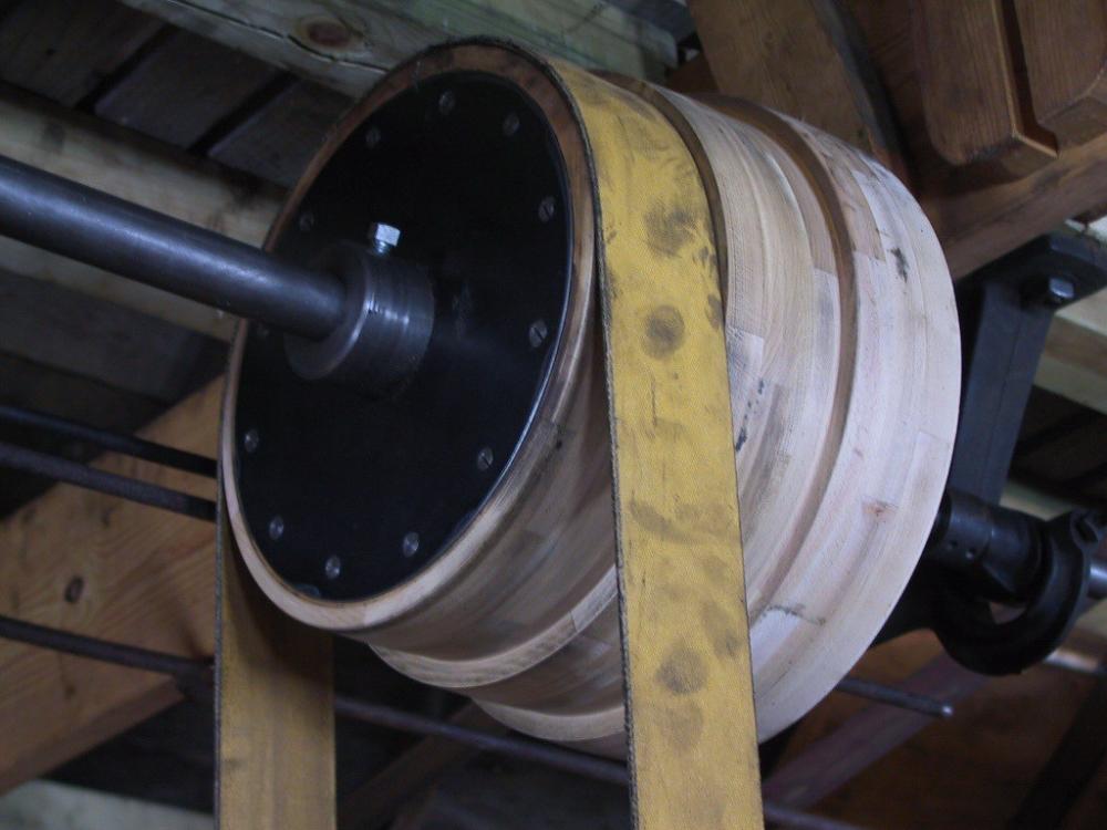
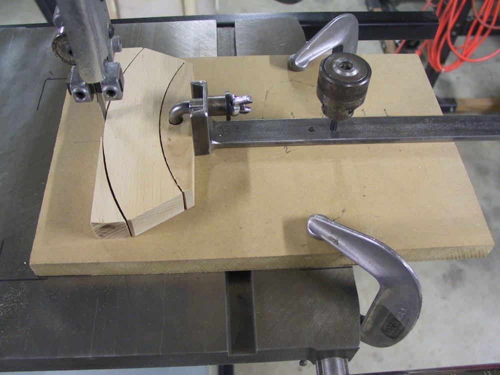
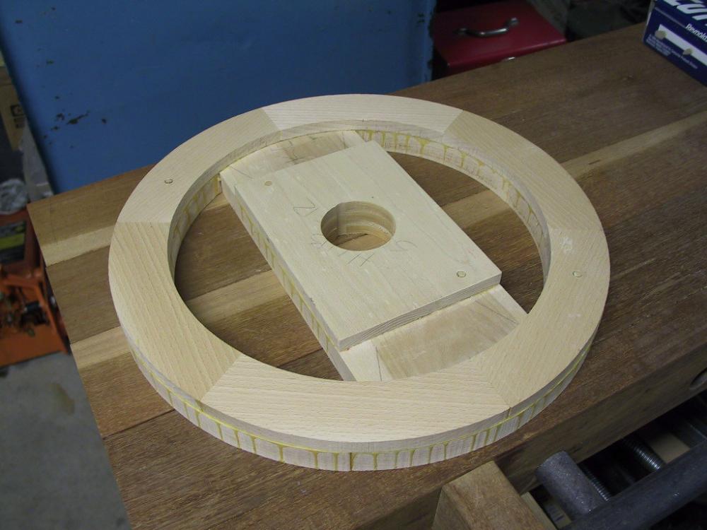
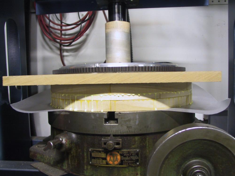
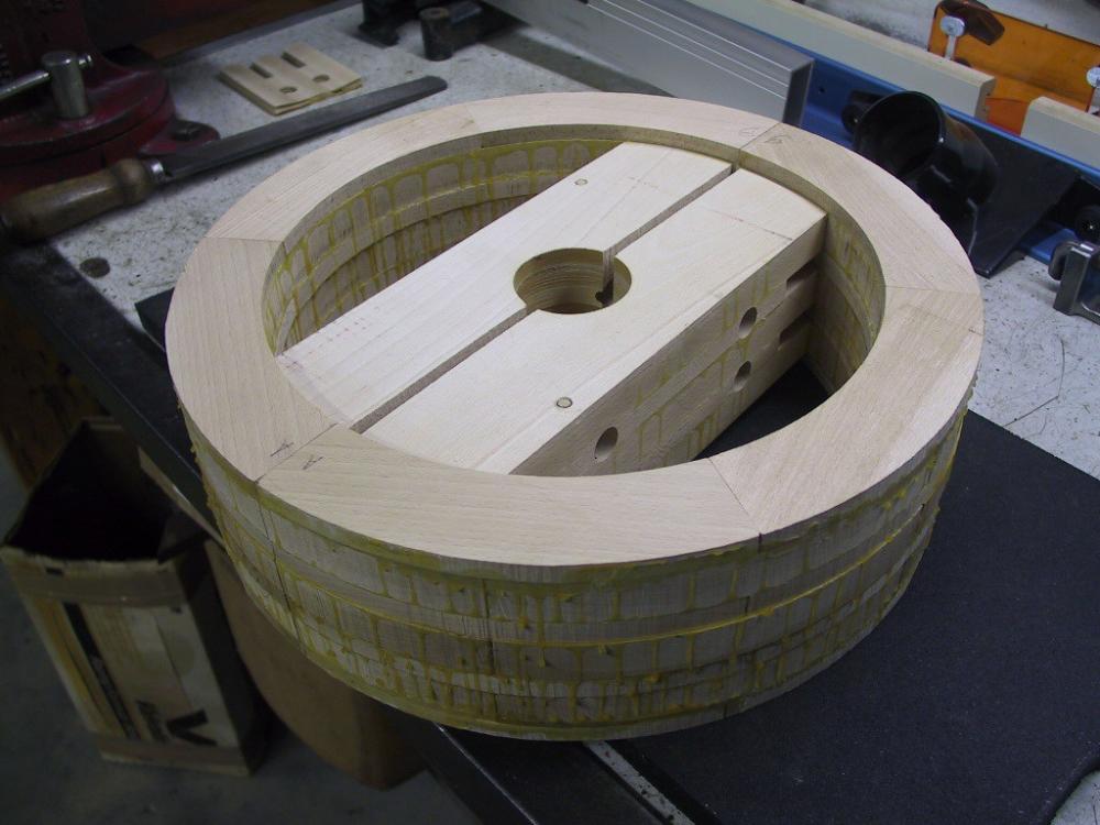
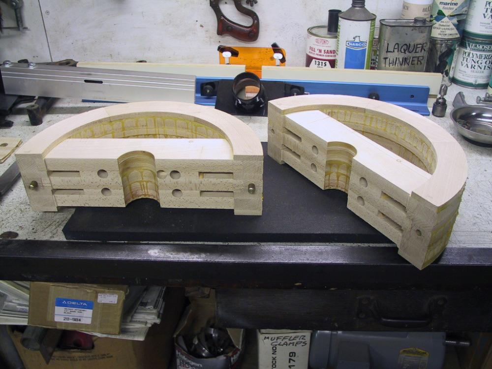
Thank you Turbo. My father-in-law (my FIL, Thomas ) and I have made some pulleys for the shop, and I think it might interest folks to see how we've gone about it. So far, we've made one split pulley of the Reeves design, and two cone pulleys: one for the horizontal mill, the other for the lathe. These are made of maple and glued with TightBond2. I have no woodworking tools other than a Disston hand saw (which I bought at a blacksmiths' conference!), so he did the woodwork and I did the metalwork and final turning in the lathe. The following shows the process to make a Reeves pulley. It's a lot of work, but when you need a certain size, there's not a lot of choice. We did this in 1999, before I had accumulated a pile of reserve pulleys. However, sometimes you still need one you don't have. At the time of this writing, he's making two more pulleys for me, soon to be used over the new engine. I made him a radii turning tool for his bandsaw to cut the inside and the outside curves of the wood. This has a simple clamp that holds the wood by pulling at a drilled hole. There are two holes in the fixture: one for the inside radius, the other for the outside radius. By changing the pin from one hole to the other, both radii may be cut in one set up. The first two pictures should explain this. The center of the pulley is composed of straight boards with an undersized hole for the bore. The entire pulley is assembled whole, to be cut in half later. My father-in-law used his press to gently squeeze the layers together. When the full stack is finished, it is cut in half and drilled for the bolts and alignment pins. This is a 16" pulley, so I was able to hold it nicely in my 19" lathe to bore the center and turn the outside, with a slight crown of course. Joel

-
What does WRT mean? Whigs, Republicans and Tories is the only thing I can come up with. And I still don't get what you mean with the trivets. You squeeze them with the press until the legs bend? Maybe I'm just too tired. I think that's it. I'll probably understand it tomorrow.
-
Oh don't worry. If you have four legs and one's too short, you have a three legged table, and everyone knows a three legged table doesn't wobble! The short one's just an extra. You probably know this, but just in case, I'll describe one way to tackle this. Don't measure. Put the table on the flattest area on your cement floor and position it so the top's level. Then take a piece of, say, 3/8" steel and put it on the floor next to your leg. (Use whatever thickness you want to remove from the legs.) Use a silver pencil and draw around the leg, moving the piece of 3/8 around the leg as you go. Do that on all four legs. Then use a cutoff wheel on your grinder and carefully cut at the silver pencil marks. Presto! A non wobble table unblemished by an unruly tape measure! Back on the pulleys, the company out of Saginaw also made a six spoke pulley, which I suppose was their heavy version, but I don' know that. It's constructed with the same bits of triangular wood though. I have only one of these, but it seems to be holding together. This design is less common, but they do turn up occasionally. It's still not as strong as the other two companies I showed.