twigg Posted August 3, 2019 Share Posted August 3, 2019 For those who haven't read my intro, I'm green as can be. I have been dreaming up plans for the past five or so months. I mostly plan to work on straight razors and kitchen cutlery, so I planned on a small propane forge. I didn't feel confident with the idea of cutting into a propane tank, so I went with a helium tank like they make for party balloons. The main difference (besides safety) is volume. These helium tanks are about 9.5" diameter and ~13" tall. I recall 20lb propane tanks are closer to 12" diameter, and a few inches taller. Since I'm only interested in smaller pieces, it works for me. The main downside was that the ceramic blanket was a tight fit. If anyone else is thinking of trying this, use four layers of 1/2" blanket instead of the usual two layers of 1" blanket recommended for propane tank forges. Lining: 2" of kaowool 8# density (two layers of 1" blanket), rigidized, followed by about 1/8" of satanite (2 coats, each approximately 1/16"), followed by one coat of ITC-100 HT roughly 1/16" thick. Floor: none yet. I couldn't fit a firebrick inside, so now I'm debating doing a refractory floor. On the other hand, on the front of the forge there is only a 1/2" lip between the bottom of the opening and the interior lining, so part of me thinks I could get away with not having a floor. (On the back opening, the lip is about 1" because I didn't take the time to do proper layout). Your input would be appreciated! Burner: I've made two kinds to experiment with. I made one 3/4" burner following David Hammer's video (shown below), and I made two 1/2" burners following Michael Porter's book designs (not shown). The forge volume, as is (without a floor), is 214 cu in, which is closer to 1/2" burner capacity. I only put the 3/4" burner in there because the 1/2" burner was still hot from the tacking. I'm gonna put the 3/4" aside for the future. Ok, I know the tacking holding that shell together is really bad. Go ahead and roast me, I deserve it. In my defense, it was my first time brazing (no welding experience either), and I was armed only with my 1/2" propane burner (not shown). Also, for the record, I do not plan on mounting the forge on that wood table. I decided to save some money on a forge cart, and just bought one of those steel racks with casters that amazon sells. I'm very short on materials, and I have yet to find a lot of scrap or drops in my neighborhood. I'm going to cut a rectangular slot in one of those shelves for the forge to sit in, and secure it with a chain and ratchet strap. Going to fabricate some kind of support for the burner just in case the positioning screws back themselves out with heat cycling. Also going to add some bolts to the joints holding the shelves up, because the last thing I want is a shelf with a forge on it crashing down. I'll show you what I come up with. Bonus photo: My crudtastic silver brazing abilities (burner collar) Yuck. As always, feedback and advice appreciated! Quote Link to comment Share on other sites More sharing options...
Mikey98118 Posted August 4, 2019 Share Posted August 4, 2019 First: you can buy a high alumina kiln shelf from a pottery supplies store in 1/2" thickness and cut off a piece for a floor, or buy a five pound bag of Kast-O-lite refractory cheap through this forum. Take your choice; either one is a good way to go. Next: how fortunate it is that you haven't put legs on that forge yet. You still have the opportunity to rotate it 90 degrees, and turn a horrible angle into the perfect angle for your burner. Quote Link to comment Share on other sites More sharing options...
twigg Posted August 5, 2019 Author Share Posted August 5, 2019 I lit the forge for the first time to see what needed improvement. 7 hours ago, Mikey98118 said: Next: how fortunate it is that you haven't put legs on that forge yet. You still have the opportunity to rotate it 90 degrees, and turn a horrible angle into the perfect angle for your burner. Yeah, I saw exactly what you meant during the test run. Great idea, thanks! Still need to make a few tweaks to the cart. Will post when ready. Quote Link to comment Share on other sites More sharing options...
Mikey98118 Posted August 5, 2019 Share Posted August 5, 2019 If you are willing to use Kast_O_lite 30 as your hot face, you could even rotate the forge so that the burner is aimed slightly upward and positioned overhead, giving an even longer distance between its flame and the heating work; this would also end any worry of heating from chimney effects after shutdown. Just now, Mikey98118 said: Kast_O_lite 30 this should read Kast-O-lite 30 Quote Link to comment Share on other sites More sharing options...
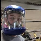
twigg Posted August 6, 2019 Author Share Posted August 6, 2019 19 hours ago, Mikey98118 said: If you are willing to use Kast_O_lite 30 as your hot face, you could even rotate the forge so that the burner is aimed slightly upward and positioned overhead not sure I understand. Do you mean to have the burner pointing slightly less than 90 degrees off the vertical, or do you mean to have the burner only slightly angled off TDC? Also, I just realized that the pictures I put in my original post make the burner look lower than it actually is, at least to my eyes. Not sure if this threw anyone off, but just in case here's a better shot. Ignore the forge cart for now. It's not finished and there's a bunch I want to improve about it. This is just the setup I had for my test run. Also, to clarify, what I saw during my test run that had me concerned was I saw the flame off the burner hitting the far wall of the lining at a 90 degree angle (see first sketch). I was hoping to get glancing incidence to encourage a nice swirl, but I got a hard sudden stop instead. Before I read Mikey's comment, I was going to make a new burner collar with a miter so the flame would skim horizontally off the top of the forge lining and get a swirl from the top down (see second sketch). Now I'm starting to think I have the wrong idea. Can someone point me in the right direction? Just want to know which design principles I've misunderstood First sketch: what I saw happening during the test run Second sketch: what I thought would be better Quote Link to comment Share on other sites More sharing options...
Mikey98118 Posted August 6, 2019 Share Posted August 6, 2019 Sorry. I meant that the position your burner is pointing at now requires cast refractory on the side wall the flame will impinge on, as well as a cast refractory floor, rather than just on the floor if you position the burner facing down; What would make worthwhile is added distance between the flame and the work. Quote Link to comment Share on other sites More sharing options...
twigg Posted August 7, 2019 Author Share Posted August 7, 2019 Thanks for clarifying. I put about 1/8" thick layer of refractory the whole way around (main reason being to totally seal the ceramic fibers. I already got lung problems and don't need more). Just to make sure I understand, you mean having the burner near vertical would be worthwhile, because it increases the distance between the flame and the work, right? Just curious, doesn't having a more horizontal angle, with the flame swirling down the wall, give an even longer distance to the work than a vertical burner? Since I have a cast refractory lining already, do you think it's worth it? Quote Link to comment Share on other sites More sharing options...
Mikey98118 Posted August 7, 2019 Share Posted August 7, 2019 Yes to both questions. However, nothing is free, engineering wise Positioning the burner facing vertical-down near one side of the floor gives less room for combustion to end; this might not be quite enough distance to completely combine all oxygen molecules with fuel molecules in the flame. A minor amount of fuel molecules left in the exhaust is a minor problem. A minor amount of free super-heated oxygen hitting heated work means instant scale formation. How much scale matters depends on what you are doing to your work pieces. If I was forge welding, I would go to extremes to keep the work pieces clean. On the other hand, a longer flame path needs to be protected in the area of impingement (that would probably be high up on the vertical section of the forge wall with an overhead burner position); but the forge's floor section still needs to be protected from flux and physical impact. Impingement areas and impact ares both need cast refractory layers about 1/2" thick. Vertical-down floor position, if done carefully, combines impingement and impact areas, so less thick refractory area is needed; reducing thermal loading. Thermal loading isn't an automatic no-no, if the forge's hot-face layer is a cast refractory like Kast-O-lite 30, or a high alumina kiln shelf, and not too thick; both ceramics have some insulating ability; unlike clay firebrick. Some people cast a hot-face layer of Kast-O-lite 30 completely around the inside of a tunnel forge, and are quite happy with it; mainly that requires a very hot burner, for fast forge heating. A mediocre burner is good enough to work well, so long as your cast refractory is fairly insulating; you will just have to wait a few more minutes for the forge to heat up. Quote Link to comment Share on other sites More sharing options...
twigg Posted August 10, 2019 Author Share Posted August 10, 2019 On 8/7/2019 at 11:06 AM, Mikey98118 said: nothing is free, engineering wise Ain't that the truth and thanks a bunch, Mikey! So I did a little more playing around with the forge. Even forged myself a (fake) straight razor for practice/experiment. Saw a couple of issues: First off, turns out my burner collar isn't the issue, it's the opening in the lining that sets the orientation of the flame. If I try and tilt the burner up, the tunnel through the lining steers it right back down. So I'm going to have to mess up the lining one way or another. Might as well fix the whole darn thing and bulk up that refractory layer! To avoid having this same issue again, I'm going to try and make a funnel shape in the opening where the flames enter the forge. That way I should be able to adjust the pointing of the flame without smacking into the lining. Another line of thought I'm having. With another 1/2" of refractory, my forge inside diameter goes down to 4" and my forge volume goes down to 113 cu in. I'm worrying I will absolutely roast this forge with a 1/2" burner. Also, after I did about an hour and a half of forging, I set off my CO alarm, an hour after I turned off the forge. I take that to mean I've got a bunch of chimney effect, and I'm pretty sure I know the reason. Mikey, I believe it's your design I followed for my 1/2" burner. It's from the book Gas Forges for Forges, Furnaces and Kilns. The reason I think I was chimney-ing was because I had an unexpected twist where my bell reducer would not thread on the burner tube far enough to meet the choke collar (it did just fine before I drilled out those slots! must've banged up the threads somewhere along the line), so there's about 1/16" of gap when the choke is fully closed. I was sick of filing at that point and left it as is. It would be an easy fix, but with the volume constraints, I'm thinking of scaling down to 3/8. This time, I'd take my burner tube and choke collar to the machine shop where I work. They got a couple of Bridgeport mills. I was just feeling too shy last time. Now I'm too sick of hand filing to care The other option, as I understand, is to use less regulator pressure on my 1/2" and position it further outside the forge. Makes me uneasy having the burner in such a mechanically unstable way. Set screws / position screws love to back themselves out during heat cycling, and I've never arc welded before, and I suck at silver brazing (as you saw!), so I'm not gonna risk that setup. Also, will a 0.023 mig tip still be the proper size for a 3/8" burner, or should I go smaller? I'd love to understand the math behind the accelerator dimensions if it's not too much to ask. Thanks! Quote Link to comment Share on other sites More sharing options...
Mikey98118 Posted August 11, 2019 Share Posted August 11, 2019 20 hours ago, twigg said: Also, will a 0.023 MIG tip still be the proper size for a 3/8" burner, or should I go smaller? I'd love to understand the math behind the accelerator dimensions if it's not too much to ask. Thanks! A MIG tip for 0.023" welding wire Has a O.O31" orifice diameter, which is too large for a 3/8" burner. You will need a capillary tube, cut down to about 9/16" long, with a 0.020" inside diameter, and you will then need to clean and shorten its end by running it--mounted in a MIG tip--over four hundred grit sandpaper. Don't forget to use a set of torch tip cleaners to de-burr its orifice after each few passes, before checking the effect of shortening on the flame. You will only be shortening the tube by about 1/32" altogether. I would suggest using stainless steel capillary tube; it can be found in heavy wall, with 1/16" outside diameter. Heavy wall tube simply works out being more convenient to deal with, if you try for a press fit with the MIG tip, compress the MIG tip around the tube, or silver braze the tube into the tip. Quote Link to comment Share on other sites More sharing options...
twigg Posted August 12, 2019 Author Share Posted August 12, 2019 Thanks! This is really helpful! I did a little more forging in the forge, in the same status as my original post, just to get a feel for things. (I already layed some ITC-100 down, so I figured I might as well play until the lining breaks down.) I decided I would like even less forge volume (got tired of reaching deep into the forge to position a tiny straight razor blank near the hot spots). I don't ever see myself working anything more than 2" wide, and I don't see why I'd ever need length (actually length seems to be a real pain). Also, my burner angle is not what I hoped. With all this in mind, I came up with a redesign plan. My thoughts are: I can cut the length by ~3" by removing the front and back domes and replacing them with flat sheet metal. While I still have the interior open, I can add another 1/2" of ceramic blanket and bury it in a 1/2" protective layer of refractory, followed by ITC-100. That would make my total lining as follows: 2" ceramic fiber blanket, followed by 1/8" satanite + ITC-100HT (oops!), followed by 1/2" of ceramic fiber blanket, followed by the 1/2" sealing layer of refractory. That should bring me down to an inside diameter of 2.75". According to the gas forges / burners book I mentioned, a 1/2" burner needs 5" of clearance before hitting the work piece. So, if that clearance scales with burner cross sectional area, a 3/8" burner would need 2-13/16" clearance before the workpiece. That I could easily achieve by slightly recessing the burner more than 1/16" from the lining. Because I will be replacing the front and back, I can rotate the forge to have any burner angle I want. With such a small diameter forge, I don't think a swirl would be helpful, so I'll just go roughly 15 degrees off TDC. Biggest remaining issue is that the burner collar will be huge relative to the burner. Oh well. I shrink the opening a bit with refractory. With all those changes, that should bring my final forge volume to 90 cu in. This might be a bit off the deep end, but here goes. I was wondering, would it be worthwhile to try and internally flare the entrance of the capillary tube with a 00 size center drill? My thought was tapering from the 1/16" tube OD to 0.025" (drill diameter for size 00) would preserve more momentum in the transition from the MIG tip to the capillary tube? I guess that would also reduce the pressure a bit. Again, I could be making a fool of myself. I just find these design challenges fascinating Quote Link to comment Share on other sites More sharing options...
Mikey98118 Posted August 12, 2019 Share Posted August 12, 2019 What makes miniature burners difficult to deal with is that every minor change you make in their design is magnified. I played around quite a bit before settling on the gas jet directions I gave you, but nothing stops you from playing around yourself I intended to state that every minor change is a miniature burner is magnified in effect. Quote Link to comment Share on other sites More sharing options...
Mikey98118 Posted August 12, 2019 Share Posted August 12, 2019 When you ask a question, I will always try to give the best advice that experience presents. BUT, for anyone who wishes to experiment; I hope they will disregards that advice, and try something new. Quote Link to comment Share on other sites More sharing options...
twigg Posted August 12, 2019 Author Share Posted August 12, 2019 Thanks! I really appreciate all the time and energy you put into this thread. I'll be back when I have made progress on the 3/8" burner. Quote Link to comment Share on other sites More sharing options...
Frosty Posted August 15, 2019 Share Posted August 15, 2019 On 8/12/2019 at 5:02 AM, Mikey98118 said: I intended to state that every minor change is a miniature burner is magnified in effect. We've had a lot of trouble with folk making burners who just don't know what a ratio is and if you don't know what it is you can't use it or apply it. My T burner instructions state the basic ratio for burner designs right off, they're based on the diameter of the mixing tube at the throat.: Mixing tube length = 8x the tube's diameter. Air intake = 2x plus the area of the mixing tube x section area. I'm sure the jet diameter has a pace in the build ratios but I just experimented till I got one that works. The initial ratio tube length : diameter is 8:1, just multiply the diameter by 8, Easy eh? If you read back through the propane burner section you'll see how many guys who can't get their burners to work properly or at all, just made the tube 8" long. Here's a little secret. Jet Ejectors aren't burners, they're intended for making vacuum over large volumes. The huge death pressure vac chamber astronauts train in is evacuated via Jet ejectors and a lot smaller than you might think. How all this ramble fits in with what Mike says is suchly. The basic ratios remain the same no matter the size. Soooo if you're building an induction device with a tube 10' in diameter a couple inches is meaningless, 2" = 1/124 a 1:124 ratio, meaningless. However the margin of acceptable error when your base dimension is 3/8" (0.375") a mistake of 0.031" is significant, same as being 1" off on a 1" burner. This is what Mike is talking about when he says minor changes in small burners is magnified. It's a matter of perspective when working at this size you can see minor errors because they're such a large % of the acceptable tolerances they can't be missed. Frosty The Lucky. Quote Link to comment Share on other sites More sharing options...
Mikey98118 Posted August 15, 2019 Share Posted August 15, 2019 Just so The smaller the burner the more carefully every detail or construction should be handled; especially the tube gas assembly. Lets try that again: " The smaller the burner the more carefully every detail of construction should be handled; especially the gas tube assembly." Quote Link to comment Share on other sites More sharing options...
Recommended Posts
Join the conversation
You can post now and register later. If you have an account, sign in now to post with your account.