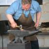
John B Posted August 21, 2010 Share Posted August 21, 2010 There was a bit of a do today at Finch Foundry and so I took the opportunity to take some pictures that may be of interest showing the drop stamps there, not very good lighting inside the works, but hopefully you can get enough details to see just how simple they were and the way they were constructed to adjust the slides and make them easy to assemble on site I would think these were proprietory items that were purchased and assembled on site, consisting of; two guides for the tup to slide up and down in between, a top casting with adjusters and location lugs on for the guides, a bottom casting with location lugs and adjustment for the guides and an adjustable location for the sow block, a latch fitting to hold the tup up when changing dies, a flat belt, and the tup with a securing device to fasten the lifting belt to and location for the top die It would appear that the smaller of the two has had a plating repair made to the top casting at some time in its history. The latch type stop for the tup appears to be missing on this unit These are pictures of the smaller one And these are the larger one which also has the latch on and a bottom die for a Devon Shovel; The waterwheel that powers this side of the shop operates these two drop stamps and a rocking shear, two trip hammers and the trip hammer's shear. Quote Link to comment Share on other sites More sharing options...
youngdylan Posted August 21, 2010 Share Posted August 21, 2010 Nice stuff John, I always loving seeing industrial archeology. I know it's a dumb question but looking at the belts made me think about line shaft machinery...... they are leather belts right? were do they get a cow large enough that they can get long enough strips. Dumb question I know but .... Quote Link to comment Share on other sites More sharing options...
John B Posted August 21, 2010 Author Share Posted August 21, 2010 Nice stuff John, I always loving seeing industrial archeology. I know it's a dumb question but looking at the belts made me think about line shaft machinery...... they are leather belts right? were do they get a cow large enough that they can get long enough strips. Dumb question I know but .... Giraffe leather, from the neck to the tail and back up again ! Actually the ones there are canvas, the same as used for driving machinery belt driven from steam engines or tractors like on threshing machines or saw benches. The bell pulls were a later addition. Another scythe making works in Sheffield can be seen here Dated 1941 it was a division of Firth Browns Steel, making scythes for the Land Army Girls amongst others as part of the war effort This works is more like the Finch Foundry set up than the Abbeydale one, the main difference being the way the hammers are lifted. The Abbeydale ones lift on a three lobe cam and follower wheel, wheras the others work off adjustable teeth on wheels which gives a greater range of hit rates. Quote Link to comment Share on other sites More sharing options...
youngdylan Posted August 21, 2010 Share Posted August 21, 2010 Giraffe leather, from the neck to the tail and back up again ! Ah HA ... I did wonder if they might be snakeskin ;) Quote Link to comment Share on other sites More sharing options...
Sam Salvati Posted August 21, 2010 Share Posted August 21, 2010 John I don't know how to thank you!!!! I still can't beleive the raising mechanism is so simple but it obviously is! I have some tinkering to do with my plan now, I like the adjustable guide arms too that's a neat trick i'll put in for sure! I love that claywheel forge video too, I watch it alot! Thanks so much for the clear pictures of every part John. Quote Link to comment Share on other sites More sharing options...
yesteryearforge Posted August 22, 2010 Share Posted August 22, 2010 I have one of those Its a 50 lber and in like new condition Fellow that I got it from used to to crush cans with Mike Quote Link to comment Share on other sites More sharing options...
John B Posted August 22, 2010 Author Share Posted August 22, 2010 John I don't know how to thank you!!!! I still can't beleive the raising mechanism is so simple but it obviously is! I have some tinkering to do with my plan now, I like the adjustable guide arms too that's a neat trick i'll put in for sure! I love that claywheel forge video too, I watch it alot! Thanks so much for the clear pictures of every part John. You are welcome Sam, I think that is what I would call a good proven design and the pictures didn't turn out too bad at all, well, enough detail to make some qualified decisions on if you decide to make one yourself. Sorry I didn't get the diameter and rpm of the lifting wheel, but that's not critical with the slip factor. The dies on them are not compatible with each other, and they are not demoed as they would have actually been used in their heyday unfortunately. Many years now since I flew the like of them, mainly making hammerheads and gear blanks. Quote Link to comment Share on other sites More sharing options...
Sam Salvati Posted August 24, 2010 Share Posted August 24, 2010 I have a thought though, it seems the difference between these and the one in the video on my d&b thread is the amount of travel your hand does. am I correct in saying the ones you posted John, that the amount you pull is 1:1 with the amount of travel on the ram? IE that if you have 6 feet of travel your ram can do, that means for you to get the ram to jump 6 feet you need to pull down 6 feet of rope on the other side? in the video though he only moves the handle of the lever a couple inches but the ram jumps a couple feet. I'm trying to figure out how to do this, less pull on your end more pull on the ram end. Quote Link to comment Share on other sites More sharing options...
Dragons lair Posted August 24, 2010 Share Posted August 24, 2010 I have one of those Its a 50 lber and in like new condition Fellow that I got it from used to to crush cans with Mike Mike, Are we talking cans or drums here. 50 lber ought to crush a 55 gal drum. Man I need one to do beer/pop cans. oops we do longnecks here. ken Quote Link to comment Share on other sites More sharing options...
Jose Gomez Posted August 24, 2010 Share Posted August 24, 2010 you can use a small idler wheel on a lever conected by a cabe to the operating lever. If you think of it like a clock, with the lifting strap connected to the hammer head on the 9o clock side, going over the top of the drive wheel (which should be spinning clockwise), put the idler on the 3o clock side of the drive wheel. That way when when you pull the lever the idler will clamp the cloth belt against the large diameter drive wheel thereby lifting the head. you might have to put a counterweight on the loose end of the lifting strap to keep a slight ammount of tension on it in order to keep the lifting strap taught when the head is dropped.....Hope I'm not the only one I make sense to... Quote Link to comment Share on other sites More sharing options...
Nakedanvil - Grant Sarver Posted August 24, 2010 Share Posted August 24, 2010 you can use a small idler wheel on a lever conected by a cabe to the operating lever. If you think of it like a clock, with the lifting strap connected to the hammer head on the 9o clock side, going over the top of the drive wheel (which should be spinning clockwise), put the idler on the 3o clock side of the drive wheel. That way when when you pull the lever the idler will clamp the cloth belt against the large diameter drive wheel thereby lifting the head. you might have to put a counterweight on the loose end of the lifting strap to keep a slight ammount of tension on it in order to keep the lifting strap taught when the head is dropped.....Hope I'm not the only one I make sense to... Falling, hitting, raising, these are all easy. What keeps it from crashing at the top or yanking the lifting belt out of the ram? Did you study the design I posted in your first thread? Short throw, simple and positive. And a proven design. Quote Link to comment Share on other sites More sharing options...
pkrankow Posted August 24, 2010 Share Posted August 24, 2010 Falling, hitting, raising, these are all easy. What keeps it from crashing at the top or yanking the lifting belt out of the ram? Did you study the design I posted in your first thread? Short throw, simple and positive. And a proven design. Shop needs a new skylight? post 14 Is the wheel free and the center shaft rotating? Or is the shaft and wheel rotating with the handle on a mechanism on the shaft to cause the strap to be pulled to the wheel taking up the belt? I read the text in the link and I think I missed something. Phil Quote Link to comment Share on other sites More sharing options...
John B Posted August 24, 2010 Author Share Posted August 24, 2010 Falling, hitting, raising, these are all easy. What keeps it from crashing at the top or yanking the lifting belt out of the ram? Skill and experience Grant, and don't wrap the pull around your hand! PS Happy birthday, Quote Link to comment Share on other sites More sharing options...
John B Posted August 24, 2010 Author Share Posted August 24, 2010 I have a thought though, it seems the difference between these and the one in the video on my d&b thread is the amount of travel your hand does. am I correct in saying the ones you posted John, that the amount you pull is 1:1 with the amount of travel on the ram? IE that if you have 6 feet of travel your ram can do, that means for you to get the ram to jump 6 feet you need to pull down 6 feet of rope on the other side? in the video though he only moves the handle of the lever a couple inches but the ram jumps a couple feet. I'm trying to figure out how to do this, less pull on your end more pull on the ram end. Hi Sam, If I remember correctly, in practice the harder/firmer the initial pull, the higher the tup rises (due to inertia I guess) its a confidence/experience thing, start gentle and work up. The one in the video I would suspect has a different arrangement in place at the top end, probably similar to the one Grant is illustrating/talking about. Quote Link to comment Share on other sites More sharing options...
HWooldridge Posted August 24, 2010 Share Posted August 24, 2010 Nice stuff John, I always loving seeing industrial archeology. I know it's a dumb question but looking at the belts made me think about line shaft machinery...... they are leather belts right? were do they get a cow large enough that they can get long enough strips. Dumb question I know but .... Leather lacing is typically cut in a circular pattern out of a hide so you get a very long string - I suspect that method probably applies to belts, too. Of course, the thickness will vary depending on what part of the hide is used but you can cut and splice to get whatever thickness and length you like. FWIW, I have read that buffalo leather makes great material for belting and was the preferred leather in the late 1800's when it was available in large quantities. It's somewhat ironic that all of the industries which produced the various technologies that conquered the Native Americans of the West were driven by the skins of an animal they depended on for survival. Quote Link to comment Share on other sites More sharing options...
Nakedanvil - Grant Sarver Posted August 24, 2010 Share Posted August 24, 2010 Shop needs a new skylight?http://www.iforgeiro...r-drop-and-bop/ post 14 Is the wheel free and the center shaft rotating? Or is the shaft and wheel rotating with the handle on a mechanism on the shaft to cause the strap to be pulled to the wheel taking up the belt? I read the text in the link and I think I missed something. Phil The hand cord applies the brake band to a drum that is constantly turning. The end of the strap is connected to an arm which is part of the winding drum. These are both connected to the brake band so that when the band grabs the driving drum everything turns together. The beauty of it is that the cord unwinds from a small diameter while the belt winds on a large diameter. This give an exact ratio between the amount the handle is pulled and how far the hammer raises. The arm does most of the lifting, not the drum. The belt just lays on the drum and it's diameter determines the amount of belt wound on in 1/2 revolution. So a 36" diameter drum has a girth of 113" X 1/2 = 56" lift if it wraps half way around the drum. Long leather belts that I have used were spliced with a long scarf joint and often were two layers so the scarfs could be staggered. And what kind of glue do they use, you ask? Hide Glue of course! Made from the same stuff as the belt. For the above there is no good reason to use leather. Just needs to be strong and flexible. Leather is unsurpassed for clutching though like with a slack-belt drive. Quote Link to comment Share on other sites More sharing options...
pkrankow Posted August 24, 2010 Share Posted August 24, 2010 That makes sense and sounds simple to devise. Thank you for taking the time to explain Grant. Phil Quote Link to comment Share on other sites More sharing options...
Sam Salvati Posted August 25, 2010 Share Posted August 25, 2010 I missed that post completely Grant i don't know how! I have read your description a couple times, and looked over the picture the same while reading now but don't get it. EDIT I get it now! Ingenious!!! a heartfelt thank you to Messrs. B&S Massey they are genious! and thank you to Grant for enlightening me and sharing. The wheel will keep rotating from the momentum of the weight unwinding the strap, unless the four rubber disc-y things are a bumper stop? Quote Link to comment Share on other sites More sharing options...
Sam Salvati Posted August 25, 2010 Share Posted August 25, 2010 I have also devised an adjustable guide setup thanks to John's pictures, quite KISS too I might add and requires no machining of very long guide surfaces either! Green is angle iron guide surface (possibly with UMHw strips or such bolted to it), yellow is the upright. there is bolts welded to the angle iron, adjusted by 1 nut on the inside, jammed tight with another on the outside. Quote Link to comment Share on other sites More sharing options...
Sam Salvati Posted August 25, 2010 Share Posted August 25, 2010 I knew I was saving those lengths of 2" square for something!!!! small prototype here I come once the consumables moratorium is lifted at the shop! Quote Link to comment Share on other sites More sharing options...
Sam Salvati Posted August 25, 2010 Share Posted August 25, 2010 Hi Sam, If I remember correctly, in practice the harder/firmer the initial pull, the higher the tup rises (due to inertia I guess) its a confidence/experience thing, start gentle and work up. The one in the video I would suspect has a different arrangement in place at the top end, probably similar to the one Grant is illustrating/talking about. John, I will on the prototype use the bellringer style. I think the same, about the inertia the ram sort of whips up, I imagine if you do it with some speed to your pull it will "jump" right up. Quote Link to comment Share on other sites More sharing options...
Nakedanvil - Grant Sarver Posted August 25, 2010 Share Posted August 25, 2010 Actually, now that you mention it there is no reason for that wheel to be connected, could be just spinning on a bushing. Quote Link to comment Share on other sites More sharing options...
John B Posted September 10, 2010 Author Share Posted September 10, 2010 Came across this Clip of the Finch Foundry set up, get a glimpse of the drop stamp drive at about 49 seconds in doesn't last long, but you can see it being threatened with working, Bear in mind the demonstrator is not a blacksmith and is just playing at it. http://www.youtube.com/watch?v=JGijcluMe2E From my point of view it is a sad reflection on how the place used to work, It's a shame there does not appear to be an actual film of it working in its heyday, Having said that, if anyone can get along to see them working, you can get a sense of the raw power from the waterwheels being harnessed. The intermittent nodding on the hammer is due to incorrect adjustment on the lifting wedges Anyway, hope it helps or amuses. Quote Link to comment Share on other sites More sharing options...
Bentiron1946 Posted September 10, 2010 Share Posted September 10, 2010 Interesting, very interesting, in post #3 by John B, in the Youtube video, I really liked the swinging chair those fellows used to sit on while working, now that was a good idea. Water power now that would be a good idea if one only had a year round stream or river to use, most likely a law againist it or something. :blink: Quote Link to comment Share on other sites More sharing options...
John B Posted September 10, 2010 Author Share Posted September 10, 2010 Water power now that would be a good idea if one only had a year round stream or river to use, most likely a law againist it or something. That is why the Finch Foundry is not allowed to use the hammers more, the Water Company insist on an extraction licence to run the machinery, and they (the water company) are afraid that it removes water from supplying the river when the leat is opened, they don't seem to get it that it only passes over the wheels and then feed back into the river, but then again, they are the experts they tell us. Quote Link to comment Share on other sites More sharing options...
Recommended Posts
Join the conversation
You can post now and register later. If you have an account, sign in now to post with your account.