

FieryFurnace
-
Posts
2,106 -
Joined
-
Last visited
Content Type
Profiles
Forums
Articles
Gallery
Downloads
Events
Everything posted by FieryFurnace
-
-
Used Clay Spencer Hammer
FieryFurnace replied to toolmaker856's topic in Power Hammers, Treadle Hammers, Olivers
If the machine is for sale at $2000 or less, I'd buy it in a heart beat. I personally assisted Clay and Walt Beckwith with a North Carolina bid and I think every participant in the class of 20 hammers, had a materials cost of about $1000-$1200. It is probably worth more than $2000 but after $2000 I'd start hesitating, as you could probably find something similar for around $2000. I put in a 3x5-foot concrete pad 6-inches thick with rebar supports both horizontal and vertical. Works like a charm. Thicker is better! -
http://chewinthefatwithchase.blogspot.com/
-
 How well does silicone bronze forge? I'd never heard of it until recently when I found out it is one of the more ideal fasteners for wooden boat building. Never heard of it being forged until now. Lovely twists. Lovely railing in general.
 -
Clinker breaker and air gate instructions
FieryFurnace replied to FieryFurnace's topic in Solid Fuel Forges
Yes you know what clinkers are. The tan chunks of metallic junk in the bottom of the firepot. A clinker breaker is not intended to get rid of the clinkers in the firepot. If you've got a really dirty fire late in the day and you want to do some forge welding, you need to dig down inside the firepot with a poker or spoon and dig all of the clinker out. (I usually don't worry about clinkers when it comes to welding. I've never had too much problem with them.) The clinker breaker's function is, when the clinker gets pretty thick and starts to block air flow, you turn the breaker and it clears out the area where the are comes into the firepot. It does so, without disturbing the fire much. It also makes the morning firepot cleaning a lot easier by allowing you to just dump all your dust and small coal and clinkers out, instead of having to try to feed all of that stuff out of little holes or a bar great. -
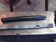
OK I was asked for some elaboration on the clinker breaker and air gate assembly I used in my new forge. So here it is. First let's start with some drawings. Here is a basic drawing of the fire pot, air pipe, and ash dump. The air gate I used is located right where the air pipe joins the ash dump and is represented by the colored in area. This is just a general overview, so you know what parts are what. Here is another drawing. This drawing is from the viewpoint of looking down the air pipe. It shows the shape of the flat bar that is bent around the air pipe and houses the air gate. OK now let's look at some actual pictures. I put my air gate right up against my ash dump pipe. You could also put it in the middle of you air pipe anywhere. It would take some minor modification of the flat bar to do this, but it would not be difficult. Here is a general look at the front of the air gate. This is a view from the back. Let's talk about the anatomy of an air gate. Basically, you need a slide channel for the gate to slide smoothly in and out of. Then you need a pipe going in and a pipe going out. Finally you need the gate itself. So here is what I did. I cut my air gate pipe to length. Then I cut a piece of flat bar, 0.25-inch by 1-inch material long enough to wrap half way around my air pipe plus a couple inches on the top and bottom for a guide. I also cut a couple of pieces to fill in the gaps where air leaked out. You can see the collar that wraps around and the stop pieces as well. In this photo I'm using a file as a pointer, pointing out the clearance slot where the air-gate handle slides in. This is the air gate here. It was made from 1/4-inch plate. It was torch cut to the same curve as the pipe. When I welded my flat bar collar to my air pipe, I hung the flat bar 1/4-inch over the end of the pipe. When welded to the ash-dump pipe, this forms the slide for the air gate to go into. A file points out the area I am talking about. Here the file is pointing out the gap at the top as well. Now, since I decided to put my air gate right against my ash dump, I had to route my air gate handle in a zig-zag patter. You will need to put a guide on your handle if you use this method, because if you do not, your point of pull will not be straight in line with the steel gate. It will bind in the hole. Make sure your point of pull is straight in line with the air gate. This air gate is extremely tight and is extremely easy to make. I welded the flat bar to my pipe on one end, and then used the torch to bend it around. It could be heated in the forge and bent around, or even cold bent. Lets look at the clinker break now. A clinker breaker is not a piece of rocket science. However, there are some things you can do to make your world a little nicer. My fire pot is 10-inches by 12-inches on top, and 5-inches by 6 inches on the bottom. It's about 3.5-inches deep. I LOVE IT! The hole in the bottom is about 3-inches square. Make your clinker breaker so that there is about a 1/4-inch gap all of the way around the clinker breaker. This allows a nice amount of air through without allowing large chunks of coal to fall through. Here is a drawing of the clearance hole in the ash dump pipe. Here is a drawing of the clinker breaker and handle from two directions. And here is a picture of my clinker breaker turned at an angle for a better view.
-
Shop notes for the end / night table
FieryFurnace replied to FieryFurnace's topic in Member Projects
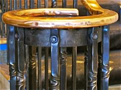
The table top is held in by the copper nails! There are 16 of them. I will be using 1/4-inch lag screws from Blacksmith's depot in my future tables. Copper will be by custom order only and will cost extra. -
Here are the shop notes for the four legged end table I just finished making. Anyone is welcome to try to make it, just don't tell everyone that it's your design or something. If you have questions I will be happy to help. The Four Legged End Table 008 General overview The table width is aproximately 16-inches The height was originally 24-inches, but the leg length in the notes below yielded a slightly shorter table. The top is 2-inch walnut strips glued together in a 20-inch square. It was sanded to 220 grit and then coated in Spar-Urethane. It is .75-inch thick. All measurements are done in decimals so that the numbers automatically get changed over for folks on the metric system. The more difficult decimals have their fractional English equivalents listed as well. These notes are not a step-by-step instructional on how to make the table. It is simply general information about stock allowances, measurements, and some notes that need to be remembered to speed up production. These notes and measurement results I got, may vary depending on your methods, tools, and techniques. Check all measurements to drawing before forging. Legs .625-inch (5/8-inch) square bar 31.5-inch cut length Upset one side 1-inch Center punch the center of the bar 3.75-inches from upset end of leg. Make a haberman square corner bend with the center punched mark in the center of the corner. The centerline measurement of the half circle leg bend is 22.125-inches. (1/8th-inch) Stock growth from square corner is 0.5-inch total, or 0.25-inch on each side of center punch. Measure 21.875-inches (7/8-inch) from center of first corner and center punch the center of stock. Make second square corner. This should allow for .25-inch of stock growth from the corner. Centerline measurement between the centers of both corners should be 22.125-inches. Bend the half circle leg around to a 14-inch inside diameter circumference. Find the common center of all four legs. Measure and trim all legs to the same length from the common center. Notch the top of each leg .25-inch in depth and .75-inch in height. This notch is done to the INSIDE of the leg or towards the side of the leg with the circle. Central Blossom Central blossom is 0.625-inch (5/8-inch) square stock. Cut length is 6.5-inches. Upset each end about 0.5-inch. Taper each end very bluntly. Isolate using round fullers, 1.5-inch from stock end, and taper down to 0.375-inch (3/8-inch.) Taper back leaving about 1-inch of original stock size in the center. Octagon the blossom ends. Finished length should measure aproximately 10-inches or more. Diagonal Filler Scrolls Diagonal filler scrolls are 0.625-inch (5/8-inch) square stock. Cut length is 3-inches. Leave 1-inch of true material in the center. Taper each end to an even consistent taper length. Scroll ends slightly on the diagonal. Central Collar Central collar is .25-inch x 1.25-inch stock. Cut length is 8-inches. Run three chisel lines down the length of collaring stock. Top Circle Top circle is .25-inch by .75-inch flat bar. Cut length is 47.5 inches. DO NOT chamfer. Upset both ends and scarf. Cold bend to an aproximately 15.5-inch centerline diameter circle. Check diameter to the average distance between the notches in the legs, once the table is assembled. Forge weld, finish circle and flatten. Chamfering is now done cold. Mark the location of each leg on the top ring and do not chamfer in these locations. Centerpunch the underside of the flat bar ring and center punch one table leg. Always line these centerpunch marks up. Drill four .25-inch holes evenly spaced between each leg. Drill the table legs .1875-inch (3/16-inch) and then mark and drill the ring. Line up holes and countersink the back of the holes in the ring so that the rivet head sits flush.
-
The double collars would look nice, but would require a more squared off design. Sounds like a good modification to this design. Instead of the arches, offer a table that is more square. This would give me another design, and increase my chances of catching someone's eye at a show! Collaring with the legs on the diamond is also a very good idea, as it would eliminate the other decorative elements that make up the center, and would allow me to offer a still nice table at a little bit cheaper price. Again, increasing my chances of picking up a buyer. I don't have a whole lot of clients that are strict traditionalists. So that's not an issue. However, I do like traditional methods or at least the appearance of traditional methods, as it looks better than modern methods.....most of the time. I'm wanting to make about a half dozen tables for this spring's craft show market. Maybe instead of 6 exactly the same, I'll do two rounded ones, two with the simple center, and two with the squared up double collar design. Sounds like it'd keep things more interesting anyway! :D
-
Would you attempt this joint without any holding aid for the pieces, if you had to make this design? If not, what method would you have used to hold the pieces in place? Always feel free to ask questions on my threads man! :D
-
I doubt it would make a noticeable difference really. Plus, you wouldn't want additional heat getting to your slide-out support rack, if you choose to nest one inside of your pipe supports. I just got all the pics for the air gate/clinker breaker tutorial, so I hope to get that up soon. No promises, as I'm very busy!
-
LOL very well! Like I said, that sort of thing don't bother me. It is all too easy to mistake or misread someone's tone, intention, meaning, point, figure of speech, and any number of things, via forums, emails, chats, etc. That's part of the reason I don't let stuff bother me. Again, I always enjoy your posts, and hope you'll pardon me for misreading. Great thoughts John and thanks for sharing. I don't see how this joint could have been made without some sort of holding aid. There is simply too much to line up. You are correct, there are 9 pieces. Of course leg positioning is critical here. The arch in the leg is a true circle so it will "nest" anywhere along the arch. I had to find the center of each leg and line them up very carefully, around the center element. Then the corner pieces had to be centered. The light duty rivet pins is a good idea and one I've used in tricky forge welding in the past. I think that would be the only option here as wires or clamps would get in the way. This has been a very interesting conversation! :D G'day to all!
-
You really think just a collar would have been strong enough to hold the legs and filler elements by itself? I don't have a whole lot of experience as regards collaring so I haven't really strength tested them. As far as what threads that I thought you had an "extremely critical angle" in, I know the one was your thread on the "Mark Aspery Hammer Challenge. I believe you sort of questioned my honesty a bit. :D There was a second one, but I don't even recall what it was to be honest. Like I said, that sort of thing doesn't bother me. If you did intentional question my honesty, I know I was being honest so why should it bother me? If I simply misunderstood your post, that's my fault, why should that bother me? :D Don't worry about it!
-
Same thing here. I always try to hide the welds. You can see a tiny, tiny bit of the weld on this one, but it takes some definate looking. I'll take a bit more care next time. :D
-
I get the idea that Mr. Gerald likes to closely critique techniques. I'm not sure that a collar here would be strong enough be itself. If all the strain was on it, it would come loose over time. Traditionally I think the route to go would have been flush-rivets either under or on top of the collar running through the legs and central element. The only thing held in by the collar would be the small tapered pieces on the corners. Every post Mr. Gerald has ever written on my threads has come from an extremely critical angle (whether intentionally or not.) I LIKE THAT! It challenges me to rethink why I chose the methods I did. It shows me to think about the why and not just the how. That's not to say that next time I'll be riveting instead of welding. I did not take Mr Gerald's post as condescending, and I'm not one to be swayed by other people's opinions alone. There's strength in a multitude of counselors and that's why I ask for other people's input. I'll still be welding on the others I do. However, I appreciate someone calling me out there, and saying, OK tell us what you did here. It makes me think about why I've chosen the methods I've chosen. Thanks Mr. Gerald!
-
I would like to be able to offer this theme in coffee, end, night, and dining tables. However, as MacBruce pointed out, the table will undoubtedly get shaky the wider the diameter. This would be increased if, instead of a true circle, the curvature of the legs was oval. I'm thinking possibly stick with the same leg design, keep the curve a true circle. Then just use a taller leg for various purposes. When a larger diameter is need, instead of the central bundle (which would go unseen in a large diameter table anyway,) use a strong flat-bar oval, rectangle, or circle to connect the legs. The legs would not touch but would be placed on the outside edges of the table and would all be attached via the steel band around the top and a steel band in the center inside instead of a collar on the center outside. Ok maybe that made no sense whatsoever. I'll just post pics when I have to build a bigger one! There are some tiny air gaps between the wood and steel band, so it can grow without restriction.
-
I never mind sharing hours.......but I didn't keep really good track here. Maybe 12-16 hours. I wasn't concerned about time because this was for an art jury, not just for an art/craft show. If/when I start producing these for art/craft shows, I will axe the copper nails and go with "forged looking" lags from blacksmith depot. I will make two jigs, one for the ring, and one for the half circle on the legs. I would then set up and do a half dozen or so at a time. I think with that I should be able to get the time down to 8 hours per table.
-
:D Yes there! I tack-welded all of the pieces together beneath the collar with 1/2-inch tacks. Then collared. I'd like to think that the strength is in the collar and the tacks were added for the convenience of holding everything together for collaring. :D
-
Primary material 5/8-inch square bar. Primary technique was the Habermann square corner bend Also features central collar and steel rivets Hand-forged copper nails Locally milled and dried, walnut top 16-inch diameter top Approximately 22 inches tall! Thoughts?
-
It may take me a couple of days. I'll put it in a new thread, in this section of the forum, entitled something like "fabricated clinker breaker, ash dump, and air gate."
-
Kentucky Smiths, Attention
FieryFurnace replied to FieryFurnace's topic in Blacksmithing, General Discussion
PM me your email! I'm still thinking about hosting an event out of my shop, if you are interested! -
The solid breakers are nice. I used a small triangular one in my last forge. Triangle or square works fine. You need about 1/4-inch gap all the way around it for air flow. Pugman! Email me when you get some time and want to come.
-
Mild Steel for struck tools
FieryFurnace replied to Ridgewayforge's topic in Tools, general discussion
Use car axles for swages and fullers....the handled ones that is. Hand held tools are easily made from coil spring in sizes from 1/2-inch to 3/4-inch. It's also great material for tongs as well. -
Kentucky Smiths, Attention
FieryFurnace replied to FieryFurnace's topic in Blacksmithing, General Discussion
Great! Let me know when and where the meetings are. I am interested, you should already have my email and if not PM me. It's a bit of a drive for me I know, but I would really like to attend. I've got some locals here that want to get together but don't want to drive so far as well. I'd love to host a meeting in my shop sometime too. Just get in touch with me via email. BTW I know Scott and Laura Kellersberger! They are really great people! -
Mild Steel for struck tools
FieryFurnace replied to Ridgewayforge's topic in Tools, general discussion
I would add that a lot of that depends on what it's going to be used for. If you are making a top or bottom fuller that's going to be used with a hand-hammer, then you might get by with it. However, if you are making tooling for heavy forging and sledge or power hammer work, you should not go with mild. I make mild steel drifts and jigs, but that's about it. I'd make my drifts out of carbon if I had enough sizes of the stuff. You'll simply spend less time grinding or reforging the faces. Try you local salvage yard for car axles and heavy springs. 1/2-inch and bigger coil spring and axles are great material. I had to bug my salvage man to death before he started collected coils and axles, but now, I can go up there any time and pick up a dozen each. $5 for axles and $10 for coils. I can get a good 5 or 6 bottom tools from a single axles. It's something like 4140 and holds up really nice without tempering.