David Kahn
Members
-
Joined
-
Last visited
-
Awesome! Thank you so much.
-
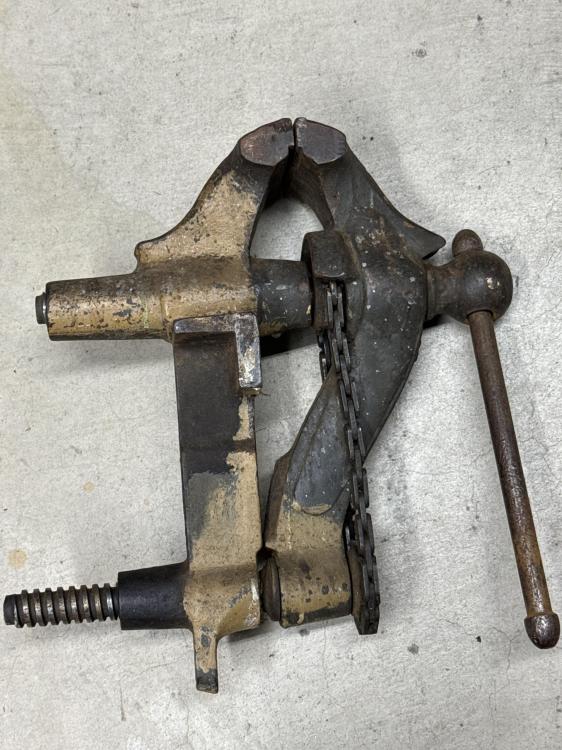
Found a smaller chain-driven twin screw vise today, and was hoping someone could help me identify the maker. Its jaws are around 4 3/8 inches, it has no post, and one of the jaws has a number 3 in the casting, which would be consistent with a Fisher size-wise, but the style is a little different from other Fisher vises I have seen, and it uses a different, narrower chain. Any thoughts/wisdom?
-
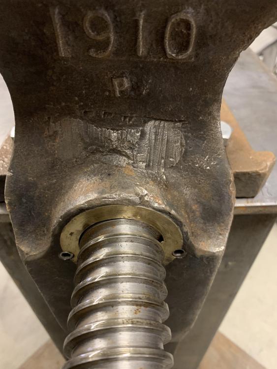
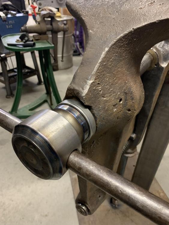
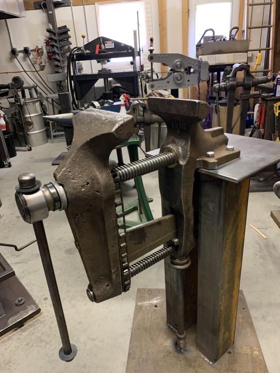
Here's the long overdue epilog to this post/inquiry. I was able to find an old-time machinist in New Hampshire (where I live) who has quite an amazing collection of older lathes, mills, etc. that he's picked up as industrial facilities have closed down over the years. His machine collection includes some surprisingly large pieces of equipment. I took the vise to him, thinking he could help me to create a large tap that I could use to clean up the interior threads on the upper screw. After some consultation, we decided instead to bore out the upper female screw hole and install a bronze replacement bushing that would be tapped to the correct thread size. He was able to create a new upper male screw with the correct buttress thread and create and install a matching threaded bronze female piece in the vise body. Today, I finished reassembling the vise, which now opens and closes properly, and will hopefully last another hundred or so years. Economically, it was probably not a good idea to buy and repair this old Fisher vise, but not every decision is economic in nature. There aren't so many of these old Fisher number 6 vises left, and I'm glad this one didn't end up in the scrap pile. Here's a couple of pics of the vise installed on a stand fabricated for it. If anyone wants more detail, I know have a pretty good working knowledge of how these vises come apart and go back together.
-
You would think material purchased through McMaster would be what it says it is, but I guess mistakes are possible. If it is really S7, it should air harden. If it were me, I’d cut a little piece off and send it in for elemental analysis. It will cost you $150 or so, but it would be very satisfying to find out what the stuff really is. And it’s not worth trying to puzzle out why your S7 isn’t air hardening until you know it’s actually S7. Fwiw, I always, always have material tested when I buy tool steel at a tailgate or from another source that is less than perfectly reliable. I once put 50 hours into making a tanto out of “S2” that turned out actually to be S5. The edge cracks from quenching oil hardening steel in water weren’t apparent until I got to the polishing stage. Made me realize that my most valuable commodity is my time, and you can waste gobs of that working with material that you think is one thing but is really something else.
-
Another thing to keep in mind is that if you’re forging and heat treating in open air, some of the carbon in the outermost surface of your work can get sucked out of the steel and react with the oxygen in the air. This sort of surface decarburization will mean that the outer surface of the work won’t have enough carbon to harden and so the tool can seem soft to a file test until you file through the decarburized layer. 1045 doesn’t have that much carbon to begin with, and you could easily have a couple of thousands of surface decarb. You might try filing a bit to see if it’s hard (or harder) underneath. Btw, you didn’t say: did you file test the tool before you tempered it?
-
Thanks very much Judson. That is very helpful. I took a more careful look at the vise, and you are correct that the threads have a "buttress" shape. Flat on the front, tapered on the back. But only the top screw. The bottom screw appears to be concentric, maybe just an acme thread? Is this type of buttress thread a standard thread shape, or was it something proprietary to Fisher? It looks like the pitch on both threads is somewhere around 2.5 TPI. If I could find a machine shop in New England somewhere that could recut the top screw and a matching nut, I would love to do that. Great point about pipe being the wrong material for a nut. Given that it only needs to be four or five inches long, drilling out a piece of bar stock might be the way to go. Lastly, do you know what the correct process is for removing and/or replacing the chain on these vises? Do you just torch heat the steel wrap on one of the links to open it and/or close it back up, or is there a trick? The original chain, which is quite worn, appears to have cast links, and the only replacement chain I could find uses stamped steel instead.
-
I have a new, cast steel 240 lb anvil that is pretty strongly magnetic. Tools and such stick to the anvil face. Has anyone else run into this issue? Is there an easy way to demagnetize an anvil?
-
I have a Fisher No. 6 (8.25 inch jaws) that has, alas, seen better days. In particular, the upper screw, which is maybe 1.5 or 1.75 inches in diameter, is very badly worn. Worse, the female part of the vise, where this upper threaded bar inserts, is also very badly worn. The worn out male and female threads on the upper screw make the vise quite difficult to operate, such that it takes a great deal of effort to loosen or tighten the vise. It looks like, originally, the female threads were cut directly into the cast iron vise body. There is no removable bearing or cartridge, which would facilitate repair. To make matters worse, the threads on these screws are something like 3-threads-per-inch, which is beyond the capability of my modest SB 13 lathe. (Not that I'd have any xxxxxxxx idea how to mount the vise body and recut cut the interior threads anyway.) Part of me wants to throw in the towel, as getting this thing working right doesn't seem like an easy project. On the other hand, these big old Fisher vises are really cool, and I would love for there to be one more of them still working in the world. It occurred to me that one option would be to bore the female threads out of the inside of the vise body, and then have the correct female threads cut into an appropriately sized length of schedule 40 steel pipe, which could then be brazed, or possibly pinned, into the bored-out vise. Of course, I'd need to find a shop that could replicate the vise screw (the male piece) and cut matching interior threads on a piece of steel tubing/pipe. I would guess this wouldn't be too difficult a task for a shop with a big lathe that is able to cut acme threads (or whatever xxx xxxx kind of threads Fisher used on these vises) at 3 tpi. (Uninformed guesses being one of my specialties.) Before diving in on something like this, I figured I should subject myself to public ridicule here. Has anyone undertake a repair of this type before? Any thoughts, wisdom, or suggestions? Is there an easier or better way to go about this? Can anyone recommend a competent, honest machine shop that might be willing to do the necessary machine work? (Alternatively, does anyone have a NOS Fisher No. 6 vise laying around that they want to see in a good new home?) Thanks much.
-
Gorgeous hammer. Congratulations! I have a 2B that was beautifullly rebuilt by Bob Bergman. Mine is a two piece as well, effectively converted into a one piece by Bob by mounting anvil and hammer onto a four foot by eight foot by two inch thick steel plate. This arrangement avoids the need to pour a special foundation for the anvil. I could never get the original Manzel oiler to work to my satisfaction, so I replaced it with a new unit which, at least so far, works great. Shoot me an e-mail if you’re interested in details. [email protected].
-
Plus, it probably makes your shop smell like Christmas cookies!
-
Ralph Sproul, who is very knowledgeable, helped me to set up my 2B. My Nazel was originally a two-piece hammer that has been converted into a one-piece by affixing both the hammer and the anvil to a 1 1/4 inch steel base plate. We put down a 1/2 inch thick sheet of Baltic birch plywood (against the floor, which is about 12 inches of reinforced concrete), with a sheet of the Fabreeka anti-vibration padding on top, so the padding is sandwiched between the steel plate hammer base and the plywood. We thought having different materials with different densities (plywood and padding) would improve the anti-vibration characteristics of the base. We installed four 3/4 inch diameter locator pins that go six or eight inches into the concrete floor, up through the plywood and padding, and through holes in the corners of the steel plate/base. We thought about using anchored bolts, but that seemed like overkill. The pins keep the hammer from moving around, although, to be honest, I'm not sure that actually would have been much of a problem. It wasn't the cheapest set up, but it really works very well.
-
There's a company south of Boston that specializes in anti-vibration padding for exactly this sort of application. Their website is here: https://www.fabreeka.com/products/. I purchased some of their padding to place under my 2B, and it has worked (at least so far) very well. If you provide them with the weight and some other characteristics of your hammer, their engineers will make recommendations about which of their products to use. Of course, their stuff is more costly than discarded conveyer belt or scrap rubber sheeting -- I think I paid around $1,000 for the pad for my 2B -- but it is designed and engineered for that specific purpose, and I think probably does a better job of protecting your floor, walls, and neighbors from vibration and noise.
-
What Basher said. Also may mean you got differential hardening, with the edge hardening and the back of the blade not, or only partially hardening. You get sabering when you clay coat a Japanese style blade and quench into oil rather than water. (Maybe someone's figured this out, but I've never heard a great explanation of the physics of why a blade bends in either direction when quenched into water or oil.) I know one bladesmith who makes Japanese style blades and quenches into oil, and he deals with this phenomenon by forging an exaggerated curve into the blade before heat treating, so that the sabering has the effect of taking some of the curve out and leaving the blade in a shape he's happy with. Suspect it takes a fair amount of experience to be able to predict how much curve to forge in and how much sabering will occur so that you get what you want at the end of the process.
-
There's no way to be absolutely certain how to heat treat the spring without having the metal tested to find out what it is. That said, most of the time, these sorts of springs are made from relatively simple steels such as 1070, 1095 or 5160, hardened and then tempered back to deep blue (550 or 560 degrees, maybe for 20 or 30 minutes). If it were me, I'd experiment on the piece you cut off, and start by heating it to just non-magnetic, followed by quenching in oil. Try not to get it too hot or to let it soak at heat too long, or you'll grow the grain and make it brittle. Once you've quenched, file test to see if it hardened. You may also want to grind down a bit and then retest to make sure it's hardened all the way through. If it hasn't hardened satisfactorily, try upping the heat a little, or quenching into a lighter oil or water. Once you get it hard, clean up the outside (so you can see color when you temper), and draw the temper to a deep blue. If you have access to a salt pot or heat treating oven, I'd try 550 degrees for 15 or 20 minutes; if not, use a torch and go very slowly and carefully. You want a nice dark blue color. One significant problem with an operation like this is that even if you use a torch or induction to selectively heat the spring only where you need to bend it, and even if you use a wet rag to try to keep the rest of the spring cool (both of which are good ideas), it is very likely that you'll end up with at least a small area on the spring that gets hot enough to draw the temper but not hot enough to re-harden in the quench, so that it will be too soft and not springy when you're done. Depending on how much stress the spring is subject to, this may or may not cause a problem. The alternative is to re-heat treat the entire spring, but that is a much bigger job, and, since you're likely to be guessing on the heat treat procedure anyway, is also more risky. Still, you might consider it if you have access to a salt pot or a heat treating oven that will fit the entire spring. (This is one reason why working the part cold is appealing, if it were possible.) Hope this is of some help. Good luck with the fix.
-
I used to try to guess what a particular batch of steel was, but too many times I discovered I'd mis-guessed only after spending dozens of hours working on a piece. Now, if I'm going to use a batch of mystery steel for something important, I chop off a small piece and send out it to be tested first. I've used these guys in the past: http://www.labtesting.com/services/metal-testing/, but a google search for "steel alloy content testing" will bring up lots of options. Usually, you can get a definitive analysis, that is full alloy content and tool steel type, for under $100. Might seem like a lot of money, but if your time has any value, it's easy to spend much, much more by being mistaken about what your working with. (In fact, I have an absolutely beautiful tanto sitting on my workbench, forged, clay quenched and almost finished. The dozen or so small cracks weren't apparent until I got to the final finishing stages. Turns out, what I thought was S2, was in fact S5, which, as it happens, doesn't appreciate being quenched in water.)