
Alan Evans
-
Posts
1,990 -
Joined
-
Last visited
Content Type
Profiles
Forums
Articles
Gallery
Downloads
Events
Posts posted by Alan Evans
-
-
15 minutes ago, JHCC said:
If the neighbor wanted more stuff, he wouldn't have had a garage sale!
He may have wanted more space for some of your handiwork...
Alan
-
1 hour ago, JHCC said:
Hmmm...now I'm wondering if I should see what I can get for it from a collector and what I could get with the proceeds.
A present for the neighbour?
Alan
-
I will also be interested to hear a metallurgists opinion...
My first (non metallurgically informed) thoughts were that the first heat was to even out the worked and nonwork hardened areas by recrystallising, and providing a regular homogenous starting point with a known grain size.
The Progen steel I have is touted as no need for temper even with a water quench...I usually oil quench my press punch-and-drifts made with it and do not temper them.
Metallurgists, please explain....?
I was idling around the information super highway a couple of weeks ago and found an interesting site...with some information about heat treatment...I was researching stress relieving of 70/30 brass. He has a few papers of a metallurgical nature which may be of interest...
http://practicalmaintenance.net/?cat=10&paged=2
Alan
-
I know them as a Clay spade, sometimes called Clay Fork...cuts a slab and prevents the suction from holding the clay to the blade....allows it to release easily.
They use the same open backed idea for excavator buckets for the same reason.
Alan
-
On 27/05/2017 at 8:19 PM, Frosty said:
snip... I still have trouble believing how they heat treat leaf springs and am not going into it it'd just confuse folk here. Heck, I'm still confused the method shouldn't work but they've been in business for more than 50 years.
Frosty The Lucky.
Oh do tell!...Nothing wrong with more information however puzzling...somebody else on here might find the pattern and logic...
Alan
-
20 hours ago, Judson Yaggy said:
Worlds biggest top bar bee hive?
Someone trying to domesticate/contain Mason bees?
Alan
-
Thank you for the kind comments, the starting point was looking for the forms which the link (sorry for the pun) trains and bikes.
Are the wheels on your bench functional or fixed Aus? I could see them either way. Set forward, with a prop (sissy bar!) at the back....but great arm rests either way.
I have seen an elongated wheelbarrow design bench in a few places. Single wheel at one end (at right angles to yours) and a pair of handles at the other so you could move it into the sunny spot or into the shade as per your inclination and the weather.
@ WoodnMetalGuy well spotted! Handy they pack so small. Since a our recent garden shed burglary the Bromptons have been sitting in the front room beside my chair, in case they come back!
Alan
-
They remind me of the frames that contain the cider cheese bags in a cider press...they both look like they can squeeze whatever is in each of the frames...though no good for cider of course being iron.
Alan
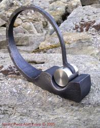
-
Benches and wheels...I designed and made a number of these for the Spen Valley Greenway cycle path which runs along an old railway line...so they were meant to be all about movement and look like they would take off and giro down the path when you sat on them...largest holes I have drifted to date in the centre bar...
Alan


-
3 hours ago, Gergely said:
Not the best for your creativity but these things help pay the bills
") If anyone recognizes this part in the second picture, please tell me its name. Thanks!
If anyone recognizes this part in the second picture, please tell me its name. Thanks!
Bests:
Gergely
2 hours ago, BIGGUNDOCTOR said:Tow bar.
If it is attached to the trailer I would call it a draw bar, if attached to the towing vehicle I would call it a tow bar.
Alan
-
Heavy duty/industrial use over here seems to be done by either screw compresses or vane...20 years ago I bought a second hand 10hp Hydrovane which has been brilliant for the shot blaster. Continuous blasting instead of do a bit, wait a lot, do a bit...when using the 5hp piston compressor...and that was with the efficiency of a pressure pot.
I feed the Hydrovane into the tank that the old piston compressor charged, and have really come round to the fact that I will never get around to rebuilding the old pump.
Rotary screw or vane pumps are much quieter than the piston compressors if you share a space with the beast.
I did also buy a 3hp piston unit for general workshop use like die grinders and paint spraying...
Alan
-
photos?
But don't worry about their complexity...there is basically a couple of bits that go up and down, some seals and a couple of valves which consist of a plain steel disc with a coil spring on one side, keeping it closed...very simple.
Bolted on top of the ram there is thick disc which is the piston, The ram then comes down through the guide/seal. For you to be seeing oil on just one side of the ram it must be getting past that seal...it will not be the piston rings. If the hammer is leaning one way and the oil is on the lower side then it could just be gathering in the bottom of cylinder on the low side..
You really will not know until you the it apart...
The lack of oil on the other side is the worrying thing, that is not going to do it any good...too much oil is not really much to worry bout.
Take photos and sketches as you take it apart.
Alan
-
Hi Drew,
As Glen suggested, add you location to your profile which helps to shape other's responses to you.
Mikey's comment about Flamefast reminds me that Vaughan's Hope Works sells their ceramic chip hearths and also a funny little gas forge.
http://www.anvils.co.uk/alcosa-blacksmiths-forges/product/1843-mk2-portable-forge.html
Although I do not have one of Cecil's (he is an old friend...very old!) Swan forges, I know lots of people who do and they are extremely robust and efficient.
I make my own and I prefer blown burners and heavy castable liners...more appropriate for my work, but like all things to do with optimum tools, they have advantages and disadvantages depending on the work you wish to use them for.
You need to tell us what sort of work you wish to do if you want specific advice.
Alan
-
I know it has become a recent fashion for everyone to use a heavy hammer on small metal, but while you are forging very infrequently....try a lighter hammer...when you get fitter or are forging heavier section metal, then go for a larger hammer.
You are probably putting more energy in lifting a 2.25lb. hammer than you are in putting it down.
The smith I learned from worked mainly in the 18 century tradition often with wrought iron...so lots of scrolls water leaves fire welded together and simple mortice and tenon joints in the frames. The full range of traditional work.
He worked full time until he was 75 odd...only ever used two forging hand hammers. Both engineers ball peins, one with a crowned flat face and the other with a full face.
Both 1.5 lb.
I am not saying it is more efficient, but it is easier on the body to start with.
Alan
-
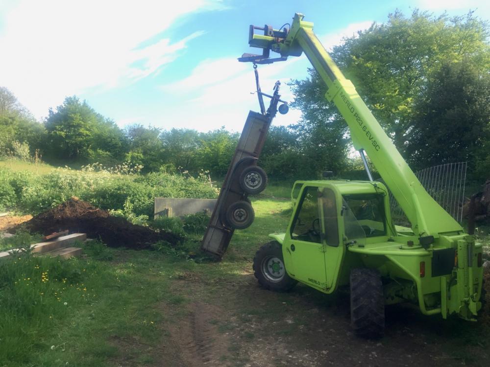
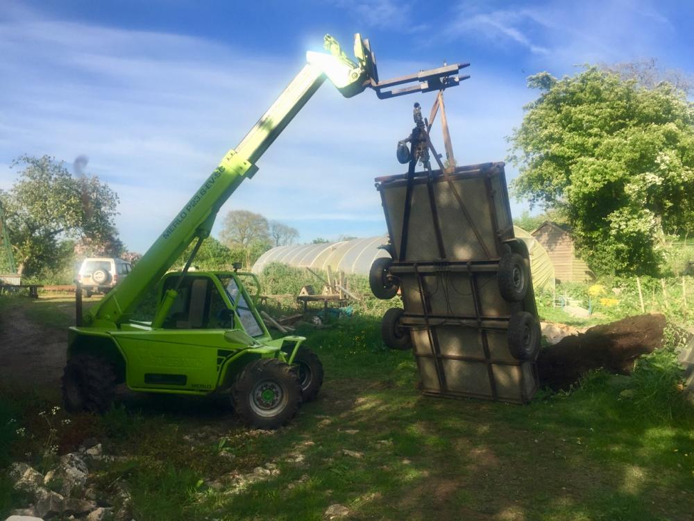
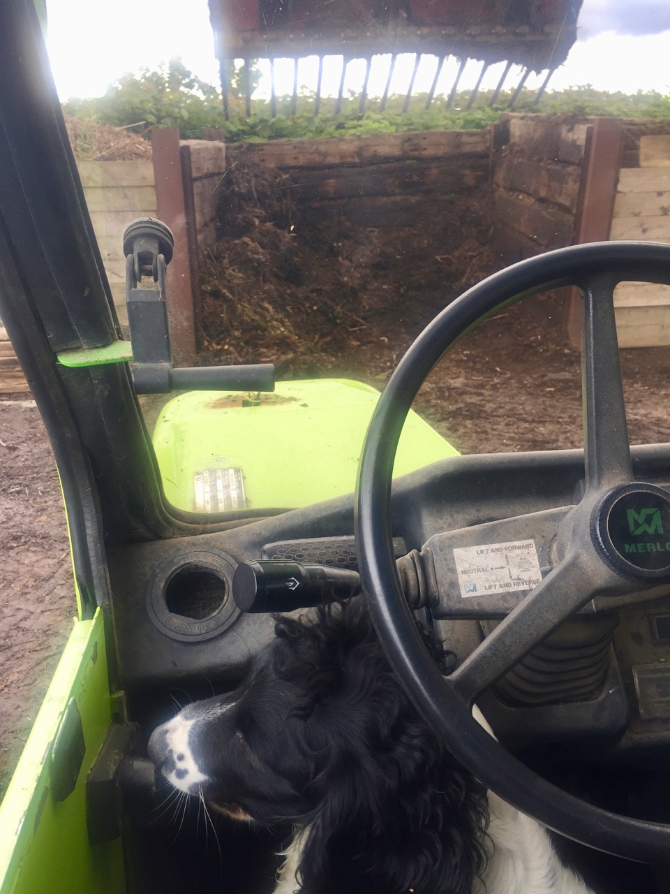
A couple of tonnes of compost followed me home yesterday.
Spent Friday emptying and turning the six bins at the Community Composting site along with a co-pilot.

Spent Saturday morning using the little Bobcat digger to load the trommel for sieving the compost. Half a dozen volunteers emptying the barrows.
Then I loaded the plant trailer with unsieved compost and took that home, emptied the trailer and then returned for the digger...
I converted the trailer to a tipper with a couple of bits of string, in order to empty the couple of tonnes of compost.
Alan
-
29 minutes ago, gote said:
I am as appaled by the fact that he admitted this thinking to a relatively casual visitor. Are you sure the MD was an engineer and not a beancounter.
Coming as I do from an airy-fairy Arts and Crafts background, steeped in the philosophies and writings of John Ruskin, William Morris and William Pye...I have always used machines, jigs and jolly to improve the piece...but not to make the life of the craftsman a drudge! Making a life and not just making a living; pride in your work; human dignity and all that.
If no skill is required of the maker they are merely used to do the bits the engineer can't mechanise cheaply. The craftsman as Factory Fodder.
I was equally amazed he would say that...it has stuck with me for 25 odd years. But then I am equally amazed that such a large industry was still based on such an archaic financial arrangement between the makers and the management!
It was such an historic ongoing arrangement between them, they obviously were both quite open about it and accepting of it.
But I could not help thinking how more efficient and financially beneficial it would be if they were working together to improve the product and the rate of production!
Having said that they must have arrived at a workable system between them...maybe the job was so tough that the makers needed the bonus incentive to keep them focussed, working for the team benefit, and safe. And both management and makers recognised this, even though they bickered about the money.
I visited Hill Foot Forge in Sheffield around the same time and they had exactly the same piece work rate system.
Alan
-
Well the 2CWT Massey went to Benprotheroe on here who has subsequently rebuilt it and has just moved into a workshop halfway between my forge and home. So it hasn't gone far!
Ben put up some photos of it in the power hammer section I think. He has also taken on a lot of Mike Roberts' equipment on a storage-in-exchange-for-shared-use basis. As that included Mikes 1CWT self contained Alldays Ben has not got around to installing the Massey yet.
Alan
-
I have a fun story about theoretical engineers versus skilled blacksmiths.
I bought a 2CWT Clearspace Massey hammer from the West Midland Stamping Company when they were closing down one of their factory sites and consolidating on on the other around a brand new Bessey closed die Forging plant. The Bessey tup was driven down by air and that in turn lifted the anvil by hydraulics which cut out the ground shaking thump of the old drop hammers that they were using previously.
They were forging huge toothed arcs which were for the Channel Tunnel boring machines. They had a rotating gas furnace which I think was hexagonal. It was charged by a forklift from the outside and rotated to present the heated batch of elements to the team working the machines. The next empty furnace section was then charged, which made it a continuous supply. The elements were around 1500mm (5') long and maybe 125mm (5") square. They pre-forged them under a 10cwt Massey Clearspace Hammer and then put them into the Bessey for the final crunch and forming.
We were being shown around by the foreman but we were spotted by the Managing Director who decided he would like to lead the tour. So we arrive at the new Bessey which is just being commissioned and the MD proudly says "We have managed to engineer out the skill with this new machine. We will no longer be held to ransom by the stamping teams who work on piece rate...the teams always try and work slow when we are negotiating the rate and then always make more as soon as it is set. This time we know that they can make 40 units a shift, so they cannot prevaricate and do 30 and then bump up production when they have the money sorted."
I found his phrase "engineering out the skill" really chilling. It has stuck with me.
However, a few weeks later I called the foreman to have a chat about furnace construction and castables...and casually asked how the stamping teams were getting on with the new Bessey machine. "Oh fine, they produced exactly 40 units on the first shift just as the engineers predicted. After a week of managing to achieve 40 per shift the piece rate was set. The next shift they produced 60 and are now keeping that up!"
Alan
-
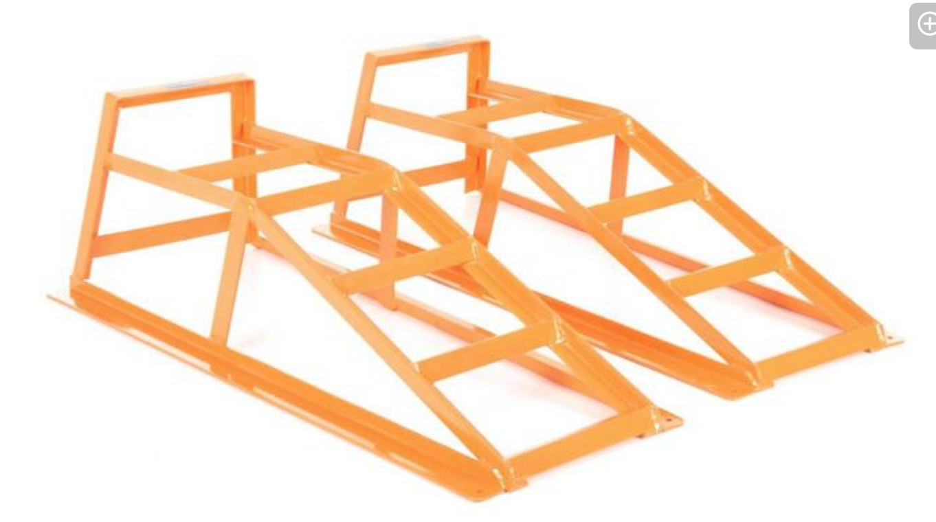
As per John's post. The Physics, the structure and the liability is covered by resting the toe of the existing ramp on what I described as a self supporting ramp extension. A wedge for want of a better description.
Alan
Something similar in form to these which the toe of the existing ramp can rest on. The only issue is then making a positive lateral location system to link the ramp to the wedge. Gravity deals with the load.


-
I have recently made and bought some ramps for a couple of different vehicles and getting the angle right is a bit of gamble. I did find that the little tracked digger will almost climb a vertical wall and the tele handler, although it grumbles, will cope with a steep pitch. The little lawn tractor could climb okay but had so little clearance under the mower deck that it kept grounding on the top of the ramp...So maybe your customer will find he does not need them extending.
The crucial thing with trailer ramps for plant is the angle they are cut to at the base...fine if you are loading on a flat concrete yard, but on uneven ground the heel of the ramp can touch and when the plant gets on it it tries to lift the ramp and/or trailer. I got round the problem on mine with a couple of simple wood blocks under the toe of the ramp which the tracks could climb without un hooking the ramp from the trailer.
In your customers instance I was wondering if you could make a self contained and self supporting ramp that pivoted off the toe of the existing ramp. It would adjust for uneven ground and remove any problems you have with trying to maintain the strength of the ramp with gussets and or plates. Structurally the toe of the existing ramp just needs to sit on top of the new ramp unit. Positive location pegs or a hinge system would work, each having advantages.
Alan
-
On 06/05/2017 at 9:55 PM, Dan P. said:
My Reiter distributes the oil very unevenly on the ram.
In use, one side is well oiled, on the other, it is bordering on dry.
Can any of you pneumatic hammer trouble shooters think of an obvious reason for this?
Thanks in advance.
Which model was it? I can't remember off hand.
I guess the problem is either too much oil getting past in one place or not enough oil getting to the other.
Mine does not drip oil...there is oil all over the ram surface though.
What happens when you increase the oil flow...just more oil on the one side?
Worn or broken rings on one side allowing more oil to get past?
Is the hammer perfectly level and the ram vertical? The residual oil does not collect on the one side overnight?
Have you checked that the delivery hose is okay? A bit of hose lining flapping on one side might divert the oily air to one side.
Can't remember, but there might be a wiper seal on the ram like on a hydraulic ram which may have worn. AC Belting in Gloucester, Mayday seals in Cheltenham or BSL in Brockworth. or Simplybearings on line if you can get the part number/type/dimensions.
Alan
-
I find the modelling can sometimes take me longer than the forging!
I did find it really handy on a project which had two 5 metre high gate side panels, each weighing around a tonne, which we had to rotate in under an archway. As they were the full height we could not just suspend them from the crane. No head room for the jib.
I modelled the panel and was able to let the software (FormZ) calculate the centre of gravity. I then made up a sacrificial bolt on bracket that gave me a lifting point just above that COG which made the panel slightly bottom heavy, but only by a few Kilos, so we could rotate it easily by hand with the crane jib halfway up the Arch height.
Alan
-
A friend's father used to sail in one of those through the fifties and Ed used to travel with him on voyages when he wasn't at school. We happened to be in California (I was a demonstrator at the San Luis Obispo ABANA conference) when he had his 50th birthday and his wife booked the evening for a party in the Liberty ship that had been restored in the San Francisco docks there.
It was really funny wandering round with Ed and him showing me all the handholds and acrobatics he had learned as a kid to circumnavigate the engine room without putting his feet on the deck. Although it wasn't the same actual ship it was to the same design...he was right back in his element and he managed it aged 50!
I seem to remember him saying that they were first world war technology so that semi skilled farmworkers/engineers who had worked on steam engines could cope with the engines...all the current tech qualified guys were needed for the fighting ships.
I gathered they also made them incredibly quickly from a kit of parts on beaches all around the SF bay. No shipyard required.
Alan
-
If you use this spreadsheet formula for the frustum of a taper (flat topped pyramid or cone) you can calculate the volume of any type of cross section, straight line taper, in round, square, octagonal, hexagonal and everything in between.
Just calculate the area of the top and bottom faces and provide the length...row 5 gives you the length of base section bar before tapering. Row 6 you need to alter by adding the area of the parent bar to give you the cutting length...the base of the taper may not be the same as parent bar if you have a step down or are forging an octagon from a round or square bar for example. The bottom two rows add in the weight depending on whether you have used mm or cm for the volume and length.
Will work with inches or feet (one or the other not both at the same time!) but the weight formula will obviously need altering.
I keep this on my phone so it is handy.
This obviously the starting point. Losses through scale and inefficient forging/multiple heats for large sections and small hammers will need to be accounted for...but it will give you a guide.
Alan
p.s when I say straight line taper....I mean not convex or concave but a constant straight taper. A convex taper will obviously have more volume and concave one will have less.


It followed me home
in Blacksmithing, General Discussion
Posted
Just as a general point of interest, the lawn mower was invented a couple of miles down the road from me in Thrupp by one Edwin Beard Buddings in 1830...well patented in 1830 at least.
He also invented the screw adjustable spanner....A pepper box pistol in 1827 more advanced than Samuel Colt's patent of 1836, and divers other improvements to Carding Machines for the woollen industry and Chaff Cutters for the agricultural industry.
I knew about the local hero lawnmower invention but have just looked him up and found the other inventions.
They refer to him now as an engineer or inventor, I always heard him referred to as a blacksmith. Creative man whatever the description.
Alan