

Jspool
-
Posts
219 -
Joined
-
Last visited
Content Type
Profiles
Forums
Articles
Gallery
Downloads
Events
Posts posted by Jspool
-
-
Thats a hansome set!
-
Nicely done. I like seeing a well executed ladder pattern. Great stand!
-
Just a thought. If you are not casting the holes with crayons and drilling them instead, why not forgo the casting all together and cut a fire brick to size and drill that?
-
Good job! Can’t wait to see your next one!
-
A lot of tool rental places rent machinery trailers that lower to the ground. A 1200lb machine is not too heavy to come a long onto one of these with minimal ramping and the use of some 3/4” pipe as rollers, Egyptian style. Same for getting it off. Keep your lines low as that hammer is top heavy, and work slow (I’m talking about an inch at a time slow) and you’ll be fine.
-
-
Ross, I see combo dies in your drawing. When utilizing combo dies your work will be offset from the center of the ram. This will encourage canting of your die carrier. In orde to mitigate as much of the canting as possible, I would suggest using longer guide plates.
1/16”of play in 12” guides is a lot less angle than 1/16” play in 6” guides. Just my 2 cents. Lookin good.
-
Aaron,
If you want the pins to blend in with the damascus bolster, I assume you will etch after the bolsters are pinned.
If (again assuming) your damascus is made from 108X/15n20, if you use a 108X pin it will be black after etching, a 15n20 pin will be silver. Otherwise, DuEulear’s suggestion would be the best option, but the most difficult for you. You could use some scrap from the damascus you purchased to turn a few pins.
-
Hi,
A little clarity, and pictures would help alot. When you say “kitchen knife” is it like a chefs knife or a cleaver?
How thick is the blade?
What is the edge geometry?
Did you mean to post “1/4” thick piece of white oak”? Thats not very thick.
Not knowing any of the above information, I will say this, I’m not sure any of my chefs knives would stand up to chopping oak.
They are designed for slicing, and retention of its edge, not chopping. Now my Bowie could chop a small tree down, but kinda suck in the kitchen!
-
-
-
The Anyang 50 ton forging press has caught my eye. It only comes with a 3 phase motor, and the US rep doesn’t think it will work with a vfd.
My current press is 5hp 3 phase and functions just fine on a vfd as long as its sized to allow for momentary overload amperage (150% or in this case a 7.5hp vfd).
It prevents the vfd from kicking out everytime the relief valve blows.
For the 10hp Anyang I would utilize a 15 to 18hp vfd.
Anyone ever run into situation where a proper vfd wouldnt work with a 3 phase motor?
-
Heres a poor pic of my 20 ton press. Kind of a split H frame as I can also feed from the side. Top and bottom I beams run to the outside and are just welded to the verticals. Been in use for 25 yrs., mostly in a factory for cold punching before I picked it up. Not complicated.
-
Ross, how many ton press will this be?
-
Hi Ross,
Is there a specific reason that you would undertake all this extra fitting? An H frame press with the cross members welded between the I beams, if properly prepped welded should be more than sufficient for up to a 50 ton press. If I was concerned beyond that, I would add gussets, but the drawing you presented would be a fitting nightmare for my limited skills, and perhaps lend no advantage to the finished product.
-
I have seen casual glimpses of a 4 column forging press made by Matt Whitmuss. I have yet to see a video of it in action, or actual specs.
Does anyone have first hand experience with this press or know of a video that available online other than the Rhino shop tour?
Thanks much for any help here.
-
That last one cracked me up
-
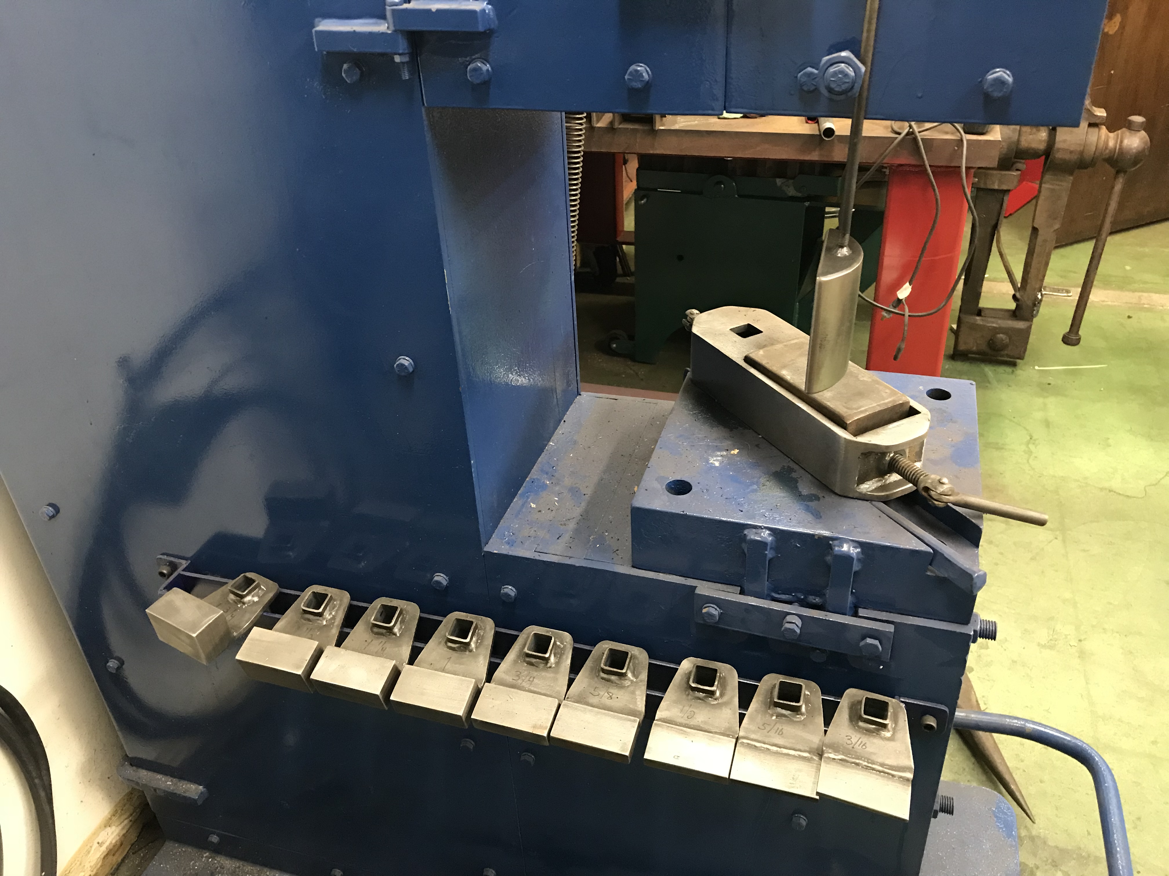
I personally would keep the flat dies mounted and when I need a drawing die, use a saddle die over it, secured by a couple bolts. Dies like this are simple to make.
This is the way my 150 Iron Kiss came to me from Arnon Kartmazov, and I can switch out dies in a minute or less.
Great system.
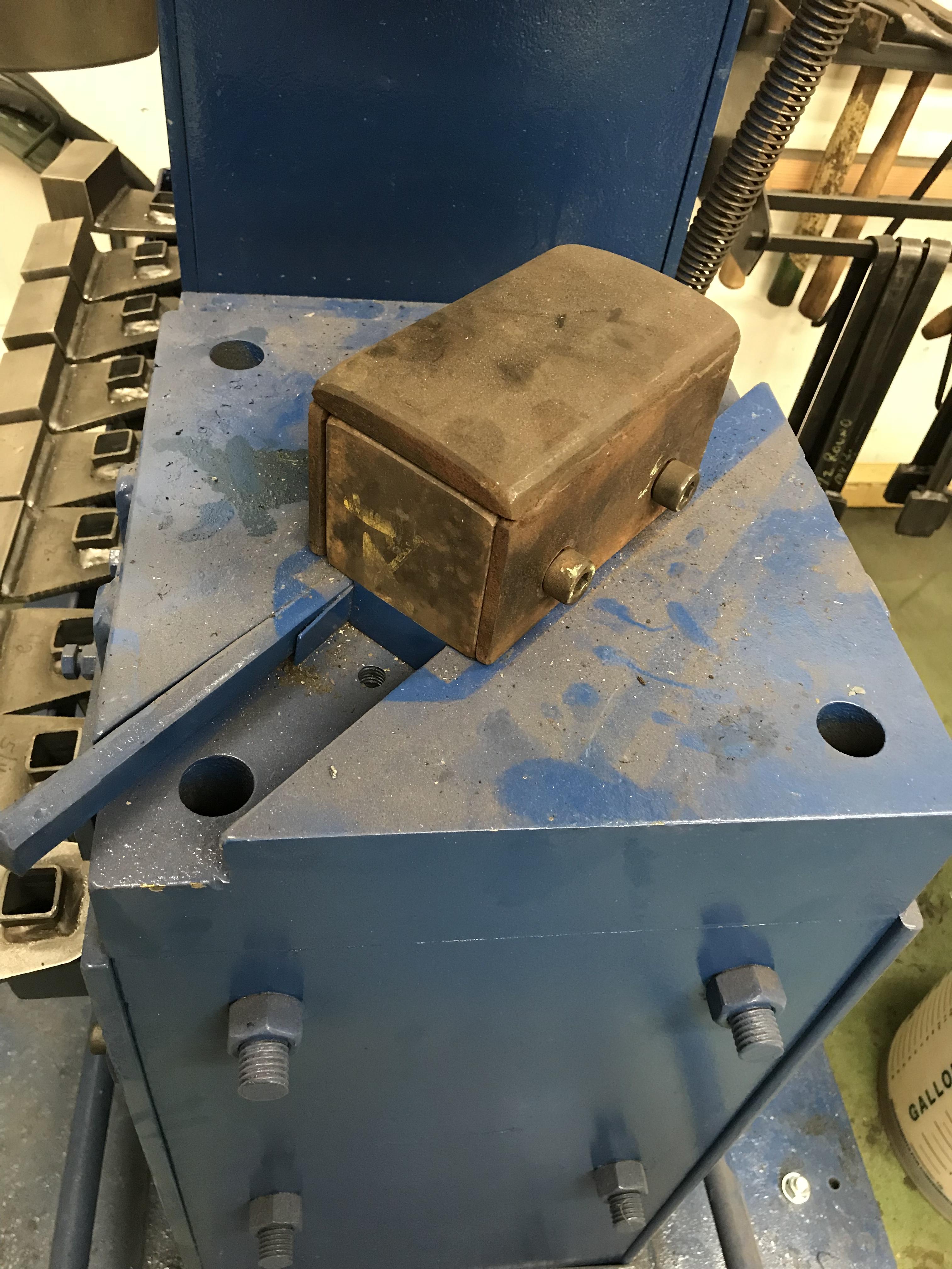
I also have a saddle with a hardie in it for mounting spring top tools.
Just my 2 cents.
Having trouble with pics. Pictures below out of order.
Some drawing dies

Hardie saddle and set of kiss blocks
Saddle drawing die
-
Wow. That’s a beauty! Great find.
-
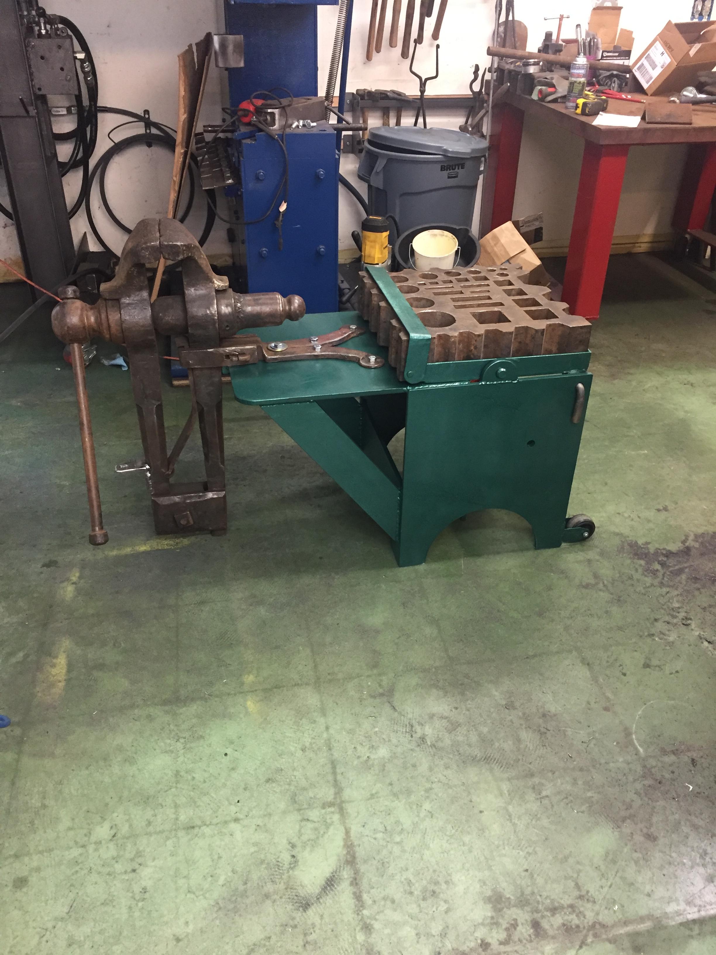
Jeremy,
I saw that picture what must have been years ago! I remember that I couldn’t figure out how it worked. Evidently it stuck in my mind, right down to the wheels and the retention rod! Now I know why I painted mine green!
-
Thanks guys. I painted it Frosty Green so I’ll always remember where the base of the idea came from! No gold however.
The grinder base is from an old barber chair.
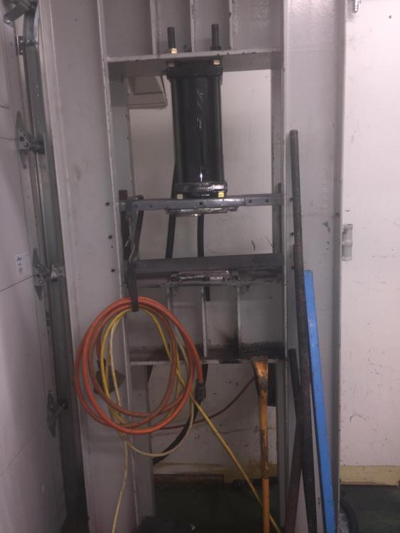
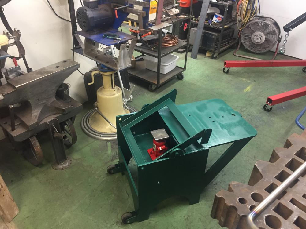
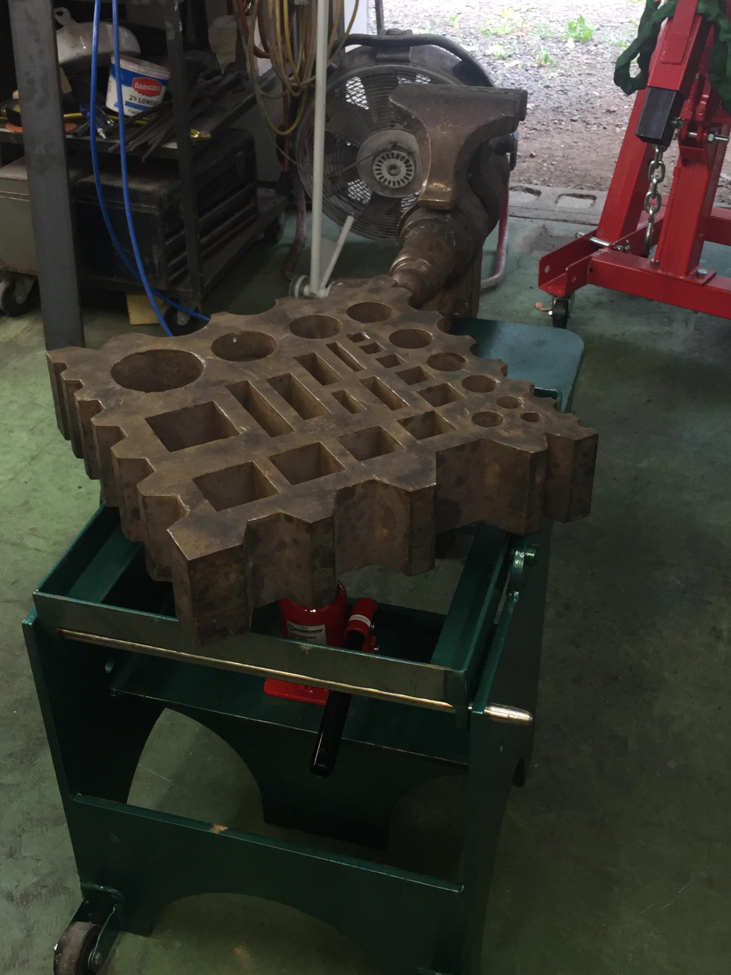
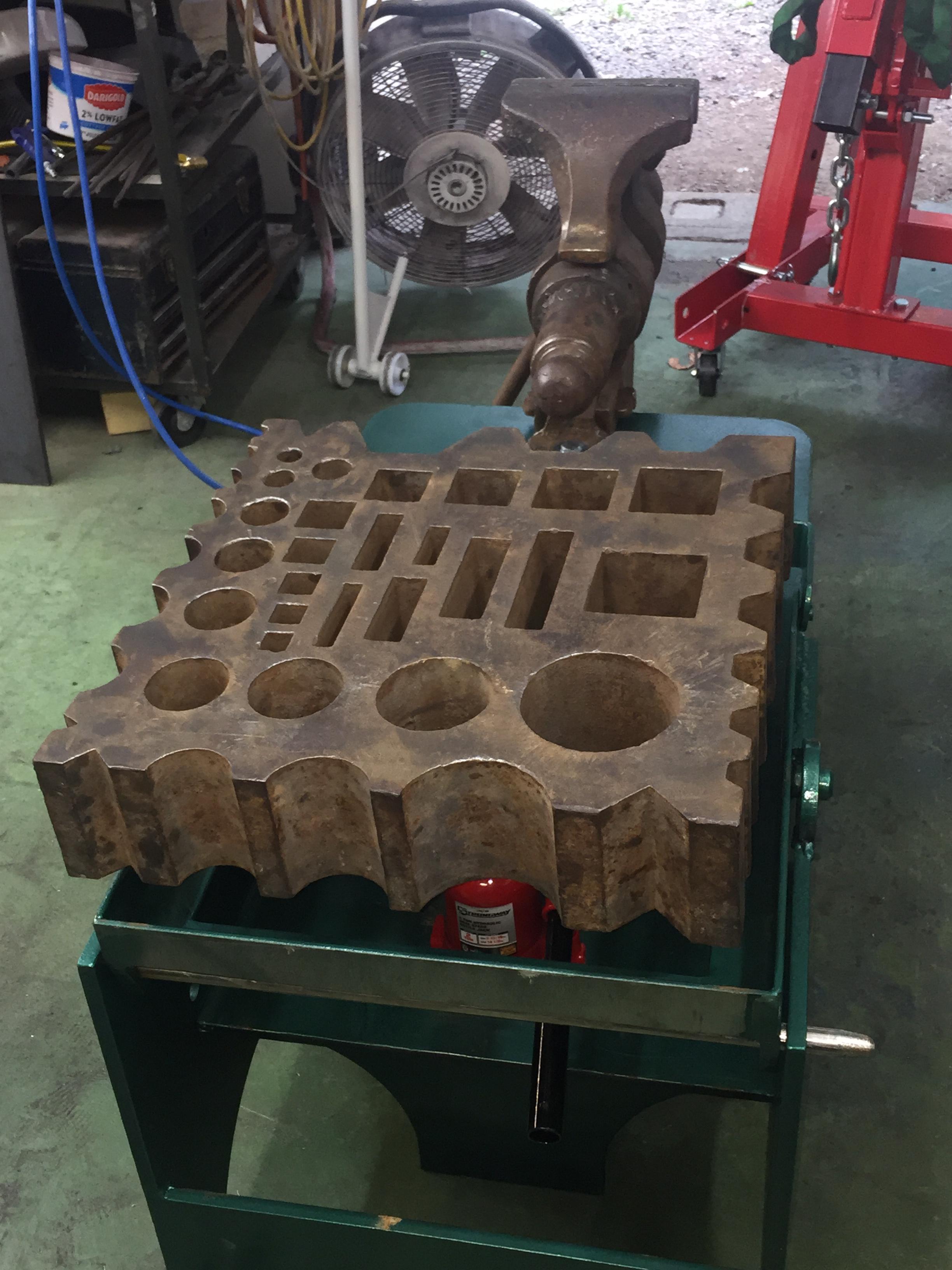
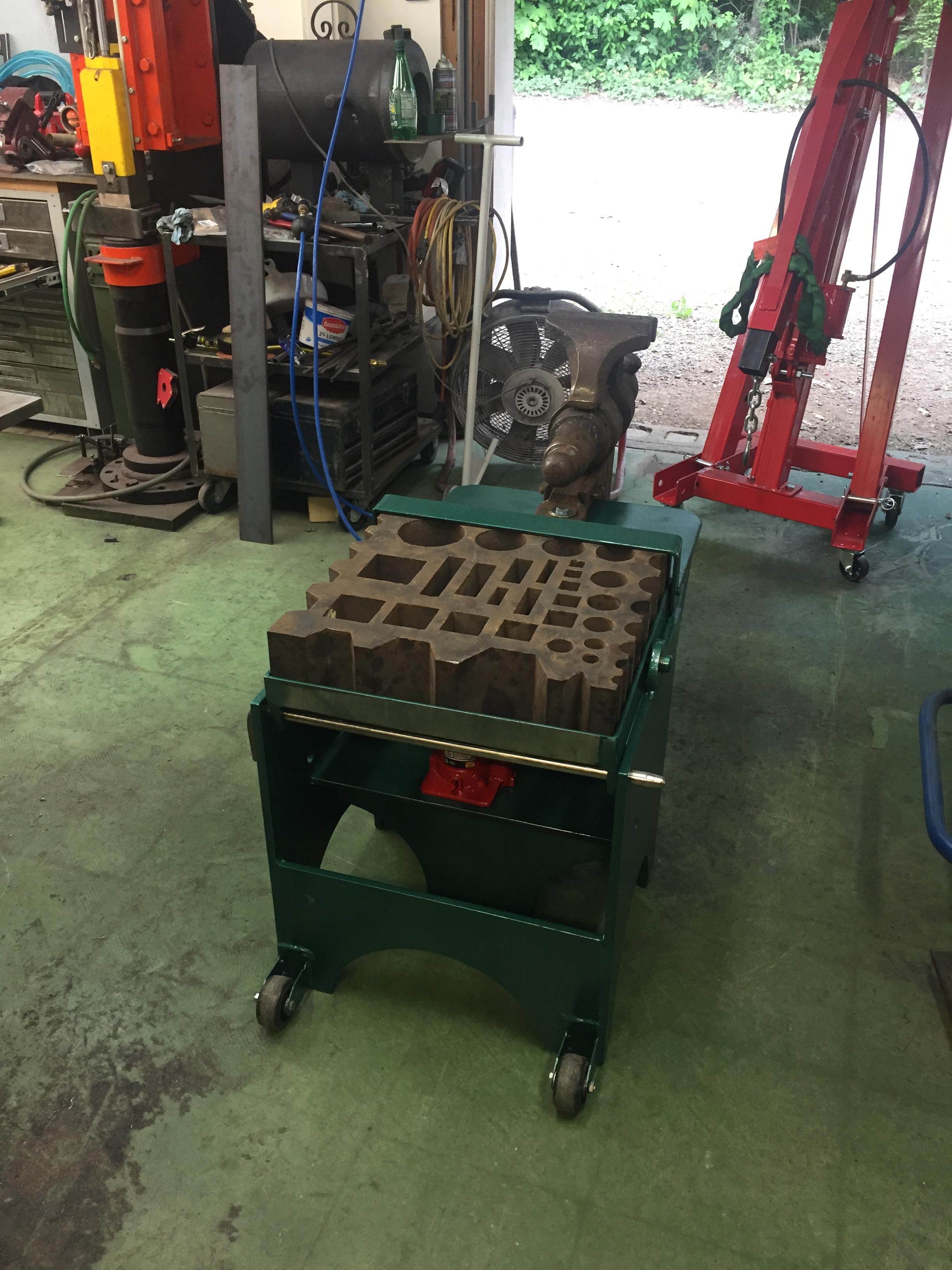
Heres a few more photos. No videos yet until I figure out how to hold the iphone.

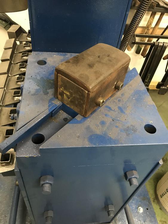
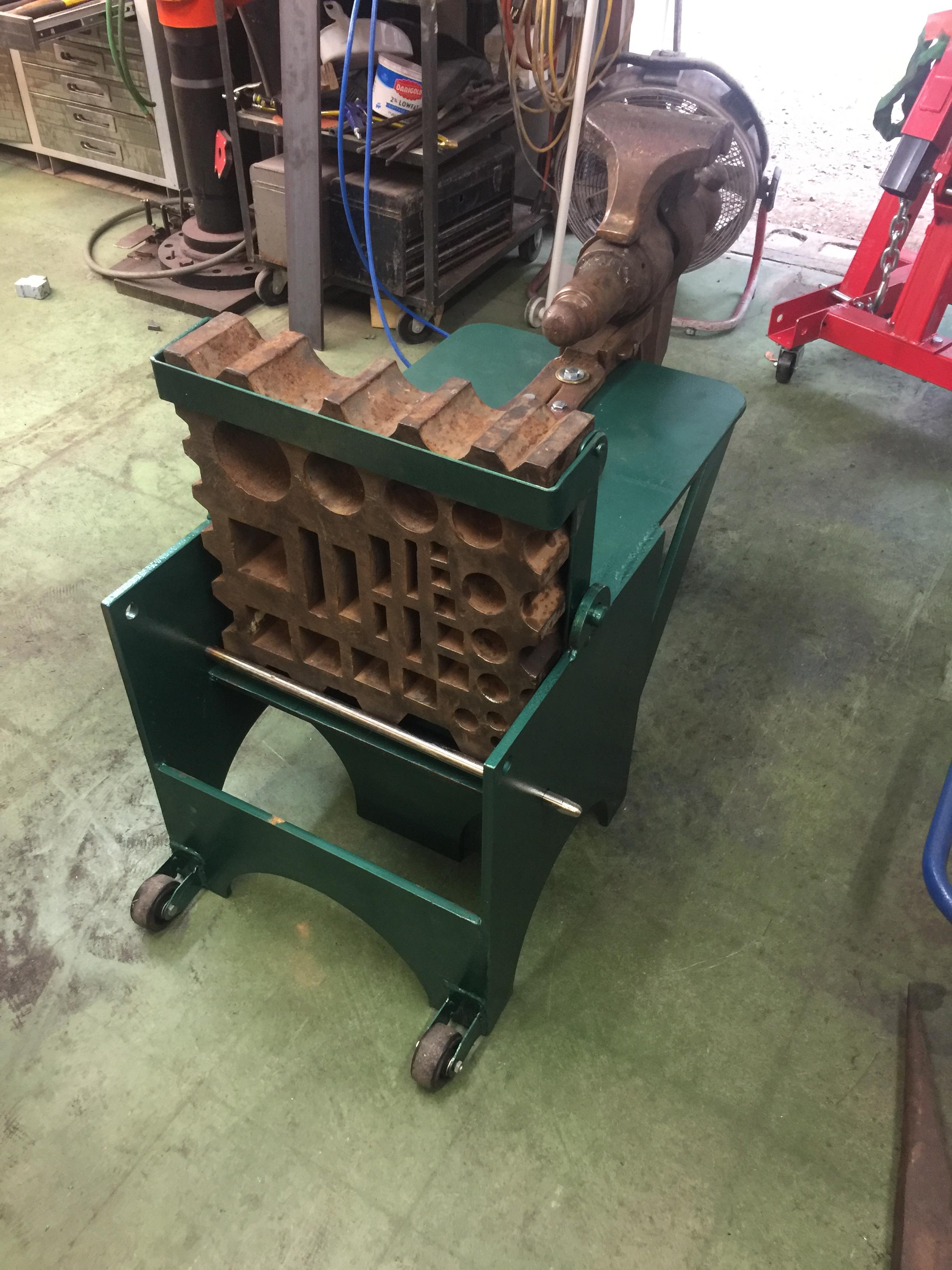
Here it is all set up in horizontal position. The securing strap should be down out of the way until its used when tilting the block to vertical.

Like this. 3/4” holding bar gets moved to make sure the block doesn’t shift.
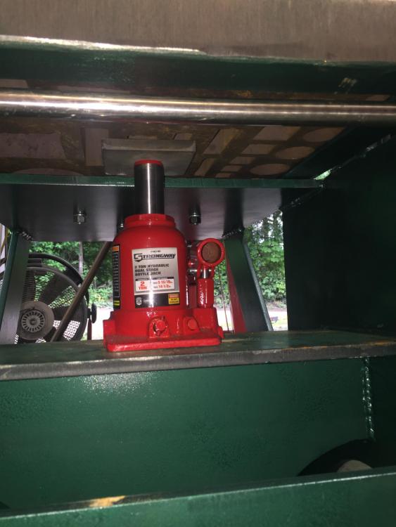
When the block is in the horizontal, center the jack and pad (which is secured) and jack it up.

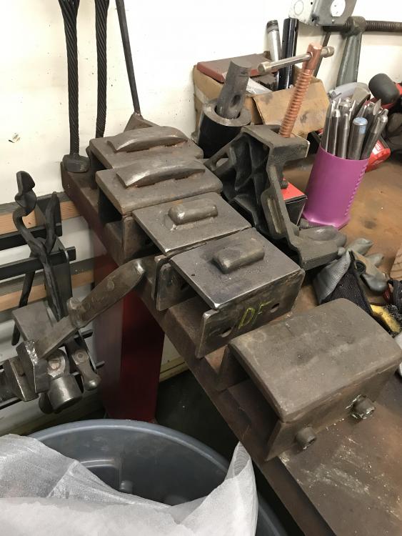
Turn the block so the desired edge will be in the up position when tilted to vertical.
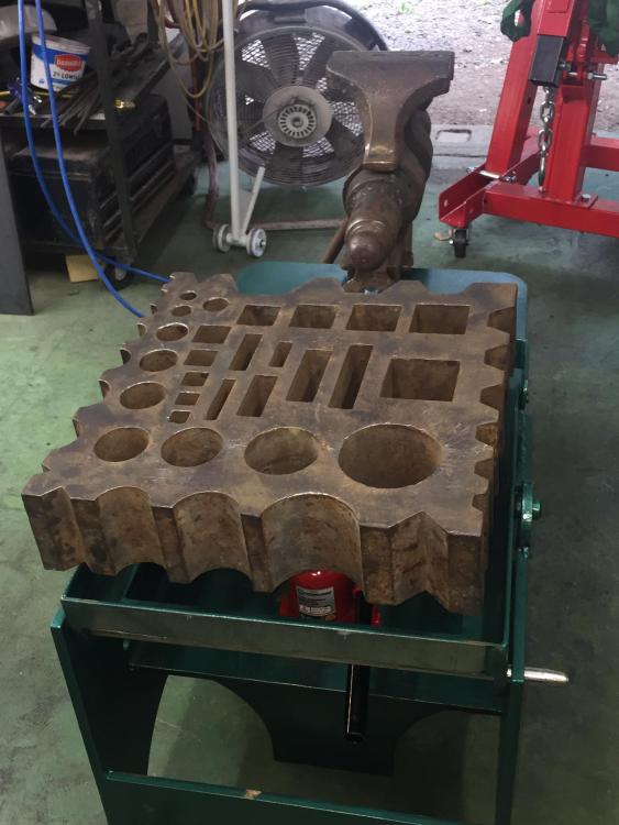
Like this. Curved swages are now on the bottom.

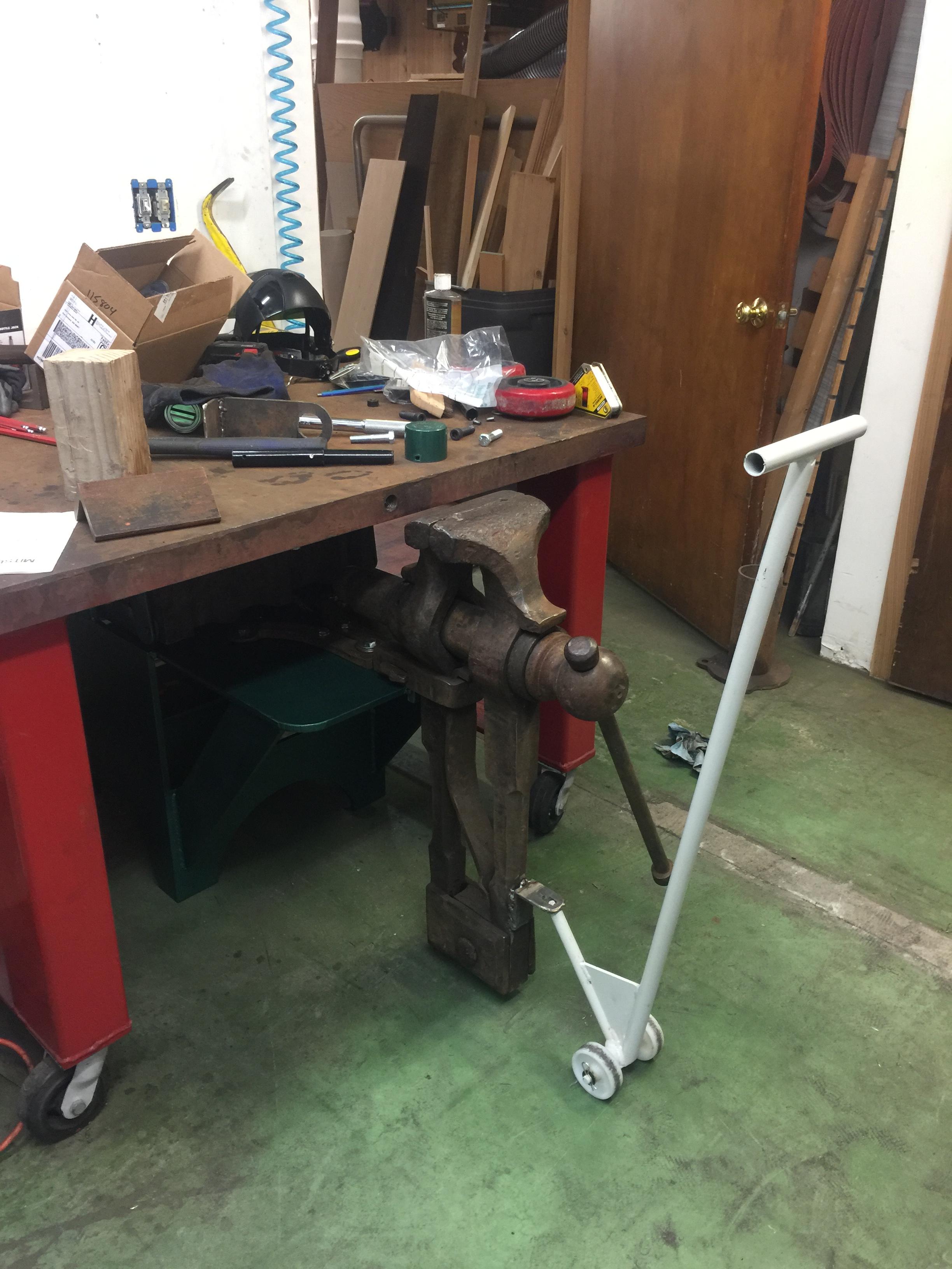
All put away in its garage. The low vise will be used a lot.
This project was a long time coming and a lot of fun to do.
Total weight is right around 700 lbs
Stand 280
Block 210
Vise 210

-
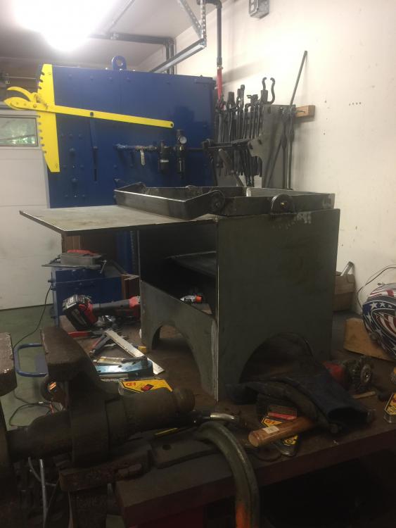
Waiting for the paint to dry on some touch up areas. Final assembly this afternoon.
-
“Whenever I get hammered you’re hitting on me! Its hardy funny and I’m fullered of it!”
-
Taking shape, and longer than I expected (as always).
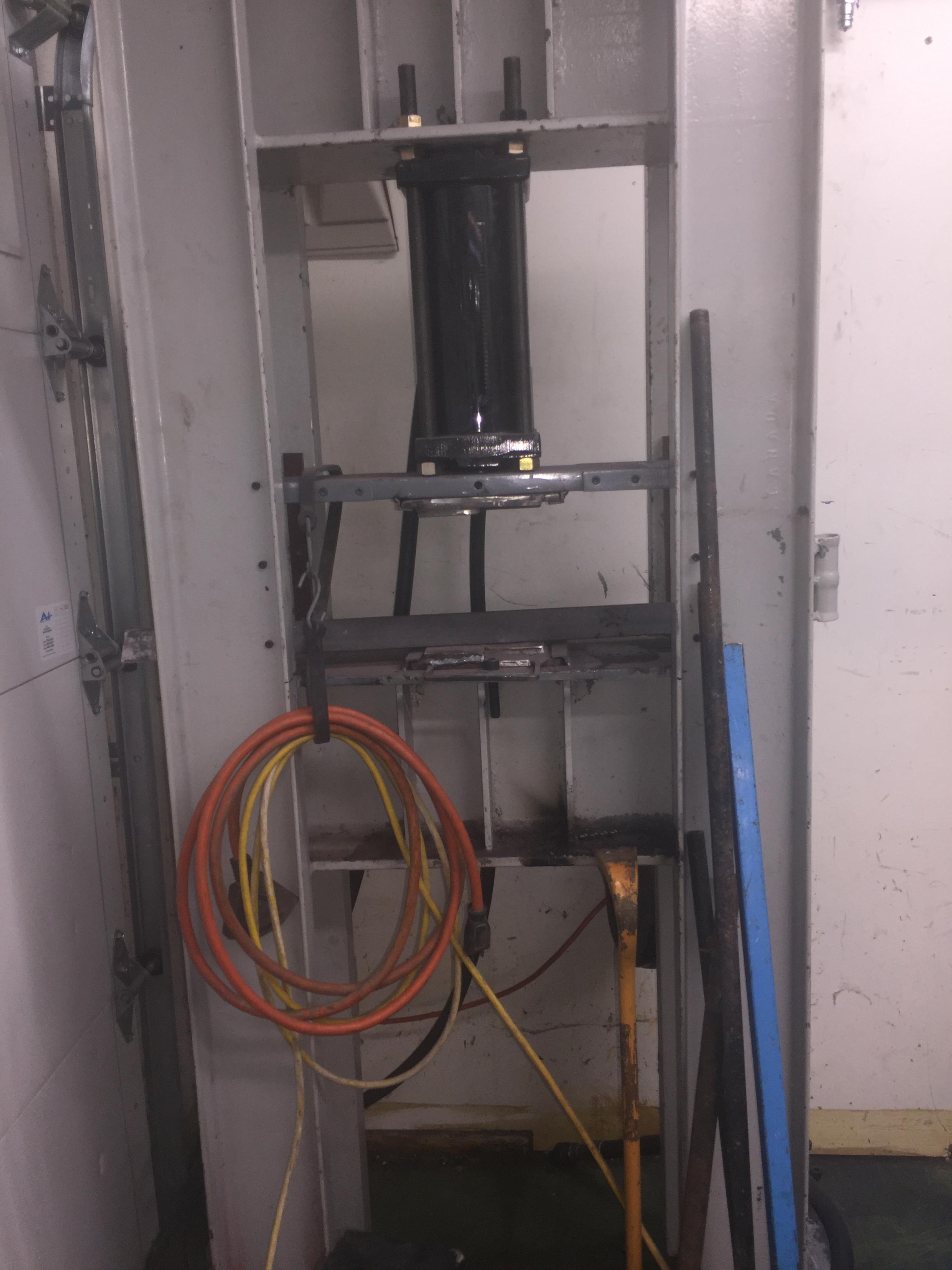


Press build
in Presses
Posted
What size breaker was required to run that 10hp motor? I assume its 3ph.