tylerdewitt
Members
-
Joined
-
Last visited
Everything posted by tylerdewitt
-
Updated my profile location to Toronto Canada. Thanks for resizing photos, will keep that in mind next time.
-
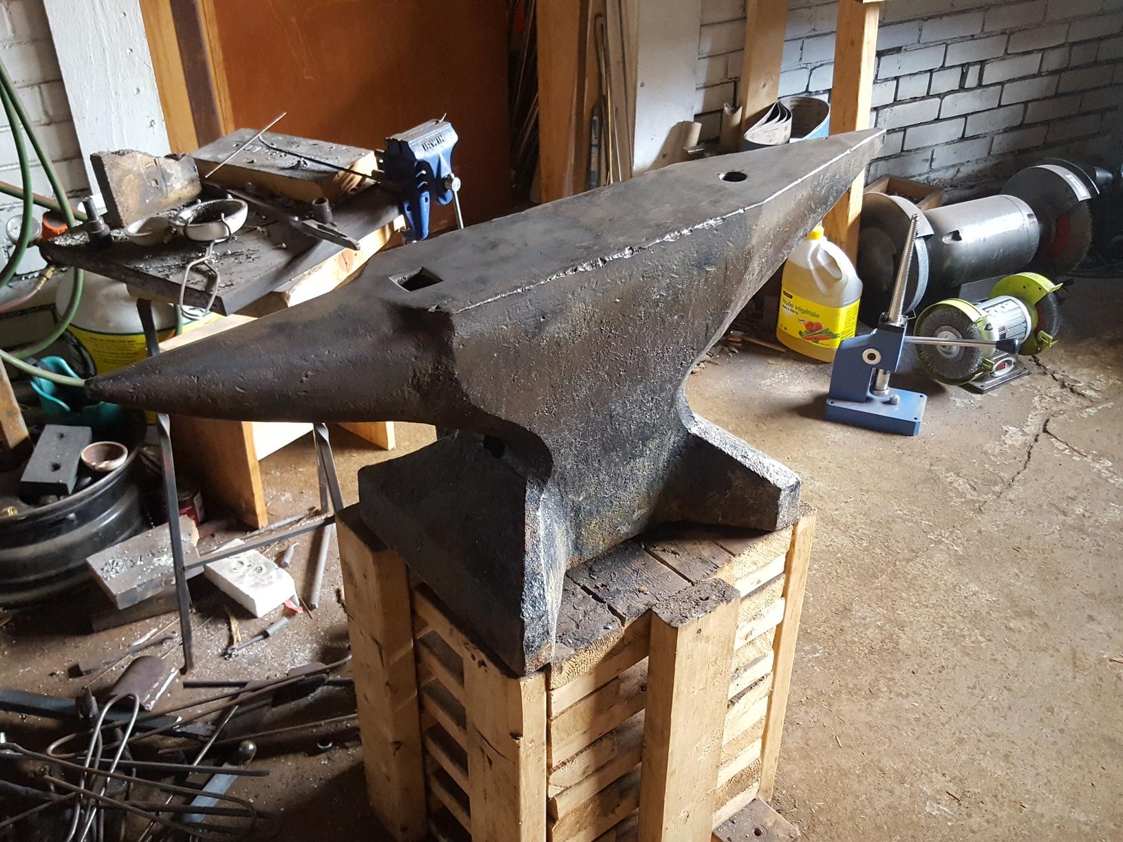
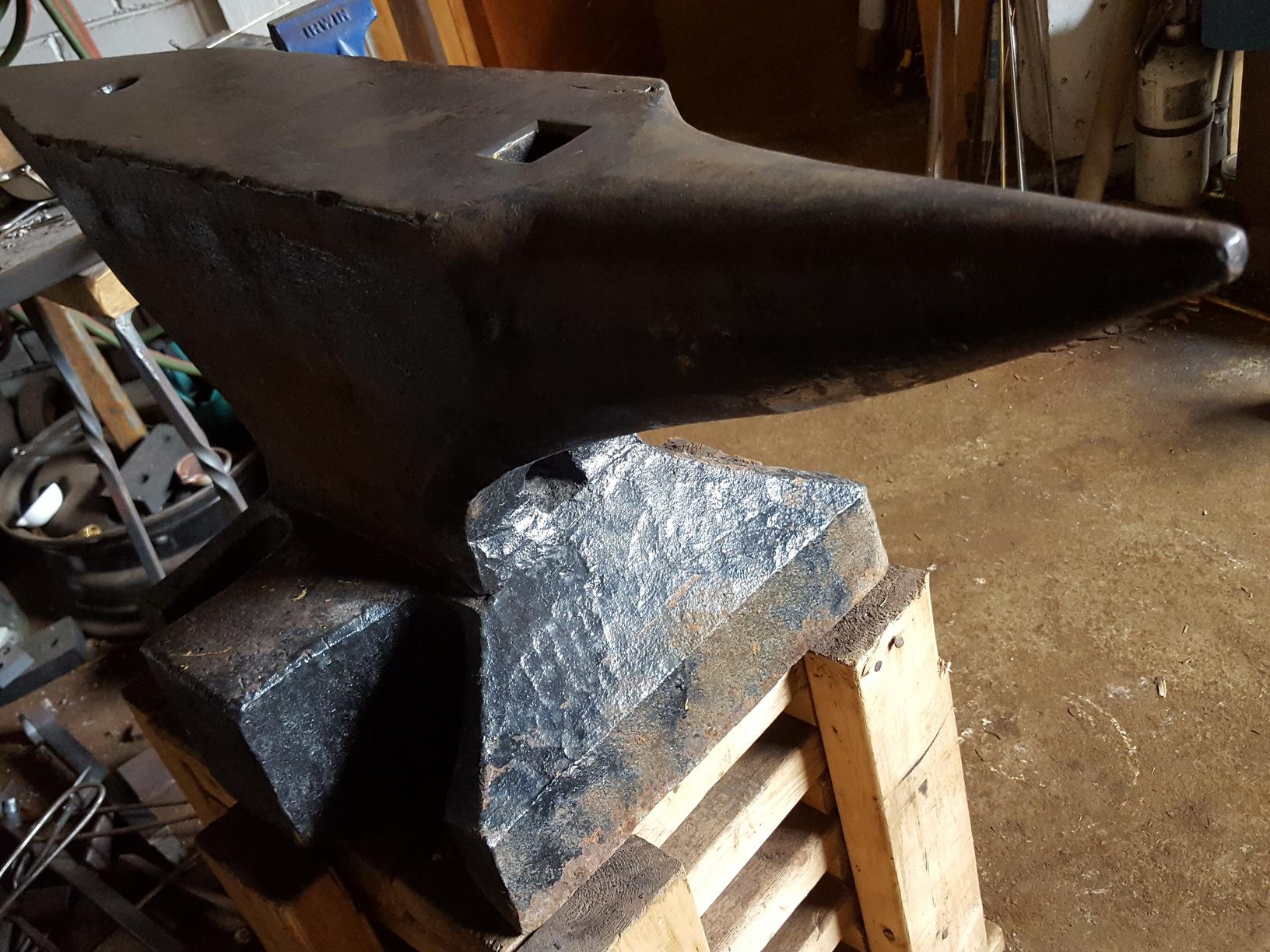
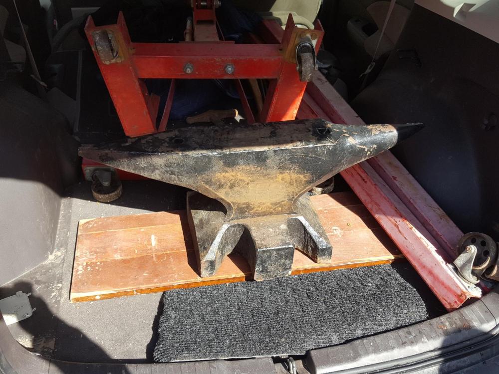
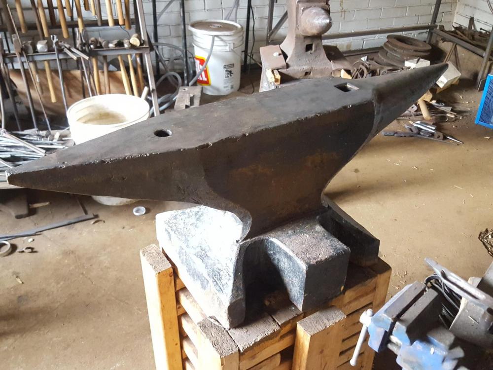
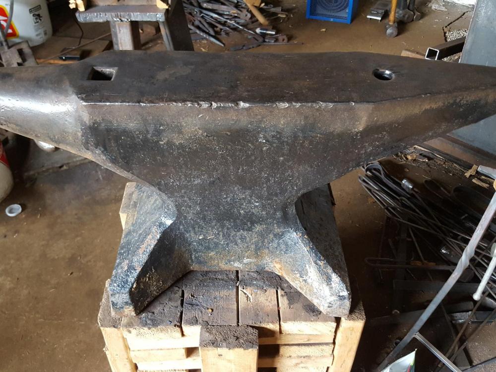
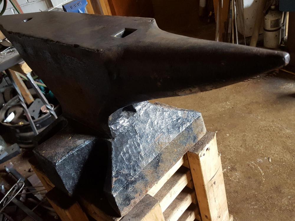
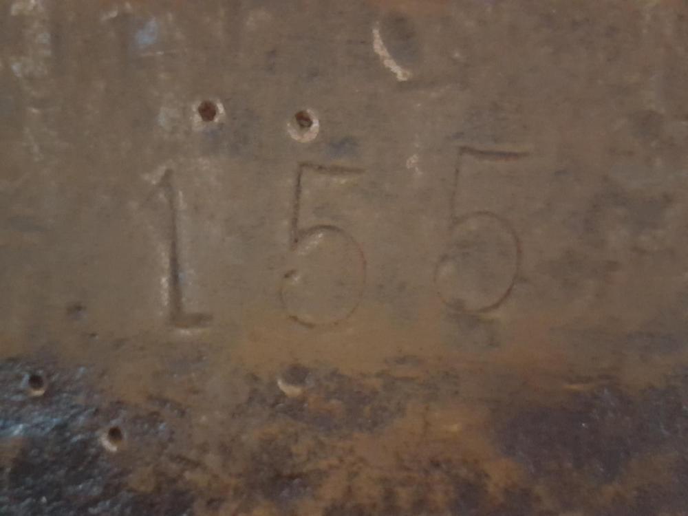
Snagged this south german anvil which come up rarely in my area. It was painted, and I should clean it more to be sure, but it would appear the only mark is the weight. Face is very hard. Any info regarding age,make,history appreciated. 155kg, 5 1/4 inch face, 13" tall.


-
Not always necessary, but in most cases the most effective and predictable way. I see inertia as a property and purpose of the anvil itself. Better to address the problem here before considering the foundation. If you can easily make bedrock your anvil, then great. In most cases it's going to be a lot more difficult. Reducing shock/vibration is generally hard. Adding mass to an anvil is a no-brainer solution. Readers can decide what's most time/cost effective for them.
-
You claim your anvil is working flawlessly beyond expectations, yet your garage floor and building are vibrating to the point of shaking things off shelves. Are you ready to concede some of your previous arguments regarding inertia? That vibration, aside from being annoying to neighbors, is lost energy that could go to deforming metal. I know you had trouble sourcing and moving a solid chunk, but it wouldn't have been that hard to laminate solid steel plates or bars. You might as well have put the mass here first, before pouring a concrete foundation. A decoupled concrete inertia block will help. But you might as well have put the mass in the anvil to start. In my build, I went to great lengths to design for minimal vibration, because I have neighbors quite near. For a 100lb ram, 1400lb solid anvil, 2" steel base plate, (sort of)decoupled concrete inertia block, and I still wish I would have poured much more concrete. You can still feel some vibration it in the ground outside of the shop. You can read my build thread if interested: https://www.iforgeiron.com/topic/49300-designing-a-50lb-guided-helve-hammer
-
I don't have any press experience, but I think what arftist is saying is that if you think about the surface area contact 2x2.5 is going to be pretty slow going. Yes in that video he squishes the round bar into a puck, but notice how little the metal moves near the end of the stroke as the surface area becomes larger. It would be even worse as the material gets thinner because it cools faster. I guess narrow drawing dies will help but the point remains that 3HP log splitter will likely be underpowered for working 2x2.5 stock. The examples shown in the video are not representative of efficiently working down a billet of that size.
-
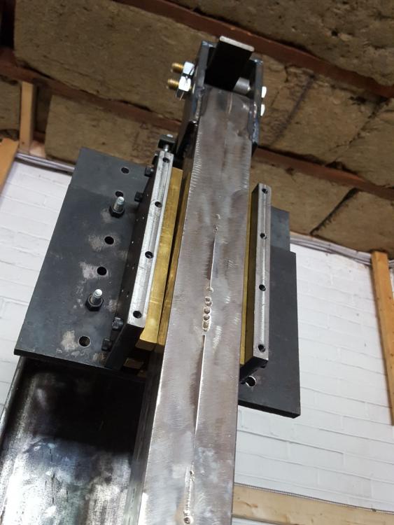
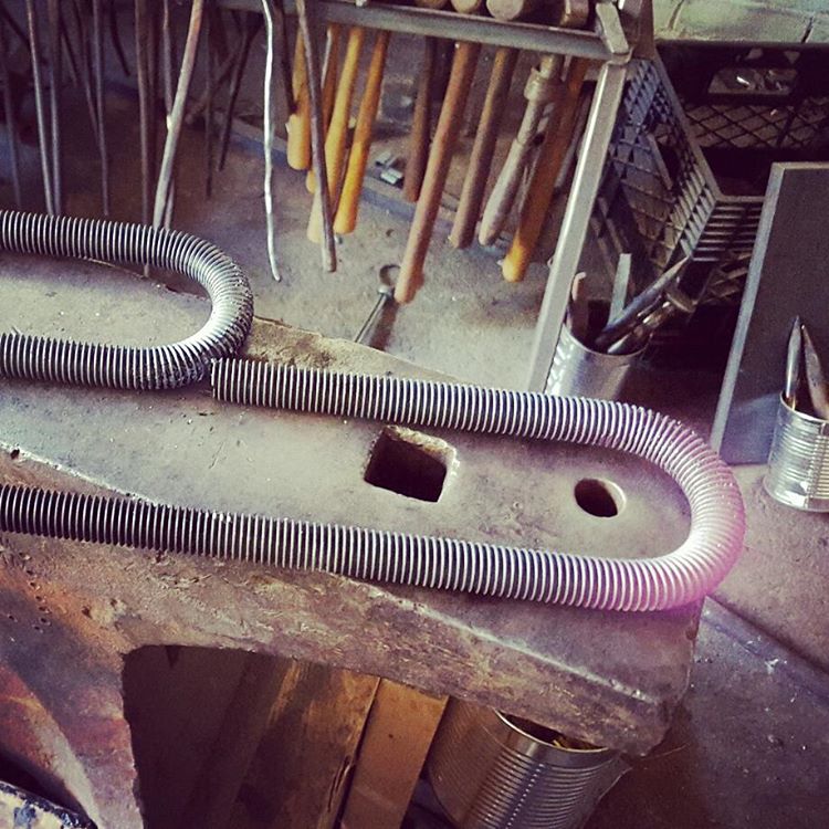
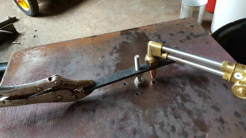
Here's an old photo from earlier in the thread, I've changed the position a bit since then. It's clamped, it doesn't slide. The movement in the videos is from the spring flexing. I think it needs to be stiffer.

-
No counter weight currently, but I've thought about trying it to see how it changes the response. Any suggestion or past experience on best practice for implementing that on a helve hammer? The ones I've seen never seemed to require it, granted they have post clutch flywheel that provides inertia. It might not be apparent from some of the videos, but yes I include a gap at tup down, I use a turnbuckle on the pitman arm allowing a great deal of adjustment. I can see what you're getting at with the spring decelerate the ram for soft blows, I'm sure I could set it up like that specifically, but I was hoping for the ability to control that via the clutch. I definitely need to stiffen the spring pack.
-
Finally got around to filming the hammer in action, videos below. After building a power hammer, I became very busy making jewellery(go figure), hence the delay. Overall I'm quite pleased how it runs, although my only comparison was a few hours on a 120lb Kinyon that I believe wasn't set up correctly (strange control, underpowered air compressor) There's some improvements I'd like to make: run it a little faster, but I believe the spring needs to be stiffer and I'm not sure I'll get around to it. 150bpm is where it likes to run. Good speed for tooling, but could be faster for drawing out heavy stock. A few notes regarding noise/vibration: this was primary concern as I live in the city with neighbors adjacent. Noise was not so bad(shop's in a detached brick garage, I did some soundproofing, filled all steel tubing cavities with sand). However, even with giant anvil, base plate and concrete foundation you could still feel slight impact in the ground outside the shop. Enough that I decided to put 3/4" of rubber mat under the hammer. I don't like the rubber mat, it feels bouncier, but it's necessary. That reduced it enough that you'd have to have your fingers on the ground to sense the impact, rather than through your shoes. It's amazing the lengths that are needed to reduce vibration. I should have poured more concrete. As a benchmark, forging 1" round mild steel on flat dies: Next two videos show drawing RR spikes. I took off the guard to see the spring. I tried to show the control response, a few single hits and softer blows. The jackshaft/flywheel definitely helps, the hammer starts fast and doesn't coast, but you can see the spring flapping around a bit after the treadle comes up. Maybe it's just the overall stiffness, but I think the leaf configuration might also play a role, I'd like to experiment to attenuate some of those harmonics. It's also difficult to do a single soft blow. You can easily feather the clutch to pull the ram up slowly, however it's very sensitive at the "tipping point" and will too readily deal a hard blow instead. It's easier to first deliver one hard blow and then lighten treadle pressure to deliver series of soft blows. I suppose every hammer has it's own personality.
-
What model VFD are you using? I bought mine used, and discovered the previous user had programmed a parameter that limits the output current.
-
Thank you arftist! Will be a while until I have some presentable videos, but I will share them here. Still thinking about the fact that last Monday morning I had an assembly of parts, and in the afternoon after slapping on some temporary mild steel dies, I had a machine with utility. I started using it right away for paid work. Going from no-hammer to hammer was such a leap that I questioned whether I should have just bought one in the past. It made me reflect on my reasons for building at all. Some thoughts to share for anyone considering building: It was a huge investment of time. In my case, hundreds of hours spread over more than a year. Materials were cheaper than purchasing and delivering a new hammer, but if your time is worth anything at all, it's not economical. However: I have a hammer that I can fix/maintain/improve and meets my particular set of constraints. I picked up many new skills and knowledge along the way: machining, moving heavy objects, mechanics, sources for materials. In my case, I treated it as a rite of passage. Being purely a hobbyist at the time, I asked myself if I "deserved" a hammer, cost aside. I definitely could not justify purchasing a new one. I could however justify building it: if I was to be a blacksmith/metalworker, I should be able to build my own tools. So that was the motivation. It seems to have worked out. Now that I'm selling more, not sure if I would make the same decision. I'd likely instead want to put those hours into producing things, rather than tinkering.
-
12x12 hot rolled, plasma cut. Supplied through Metalsupermarkets, I'm not sure who their supplier is. It was embarrassingly expensive, but they helped with delivery and unloading, and it was a no brainer solution to some of my constraints. The hammer runs rock solid, neighbors won't feel a thing. I'm sure I could increase the ram weight. I've been running it a bit the past couple of days with temporary mild steel dies. Had to make some adjustments to the spring pack, add spacers and stops to keep some parts from slowly shifting/sliding around. Once settled in, I'll try to share some videos.
-
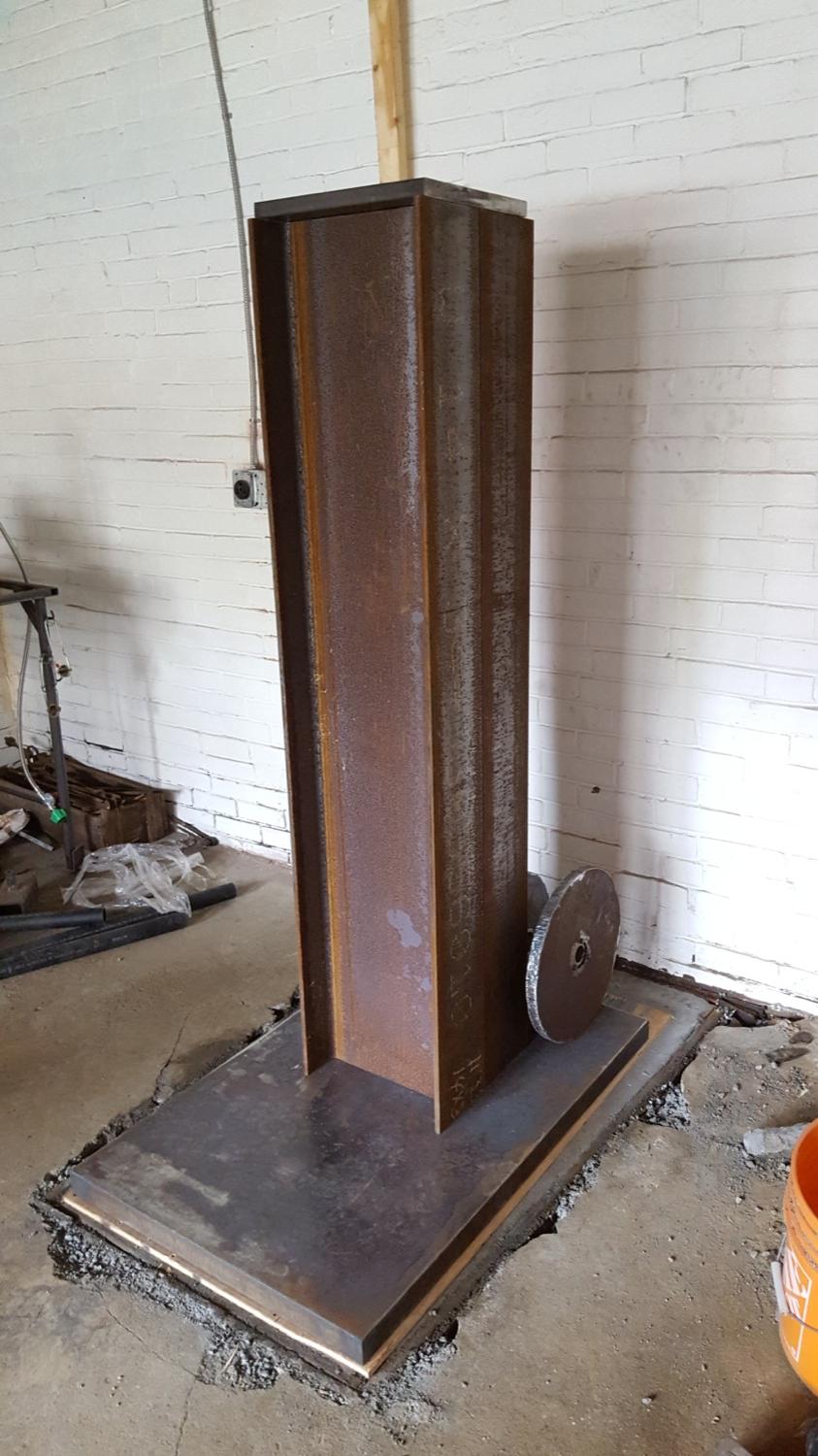
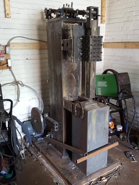
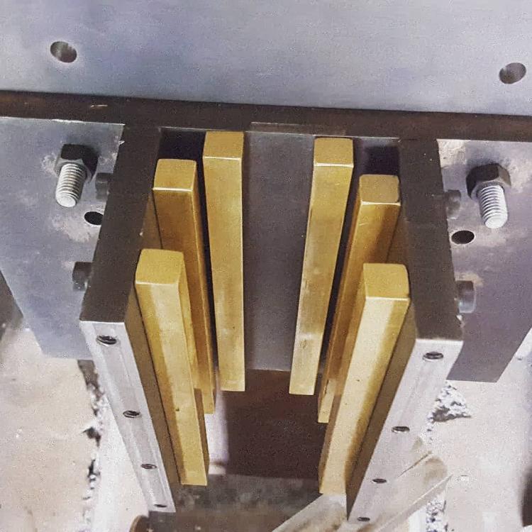
Some photos from the past six months. 3HP motor with VFD. Guide box with brass bearings, per arftist's design. Vertical position of entire guidebox is adjustable with evenly spaced holes in backing plate. Anvil is 12x12x30, overkill arguably. The ram is currently about 85lb, cycles at about 170bpm, very stable, very little vibration. Splintered some 2x4s today. Many tunings and improvements to be made, but very close now to having a working hammer.


-
Very helpful, thanks for sharing these photos. Tyler
-
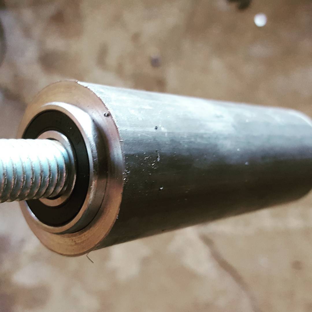
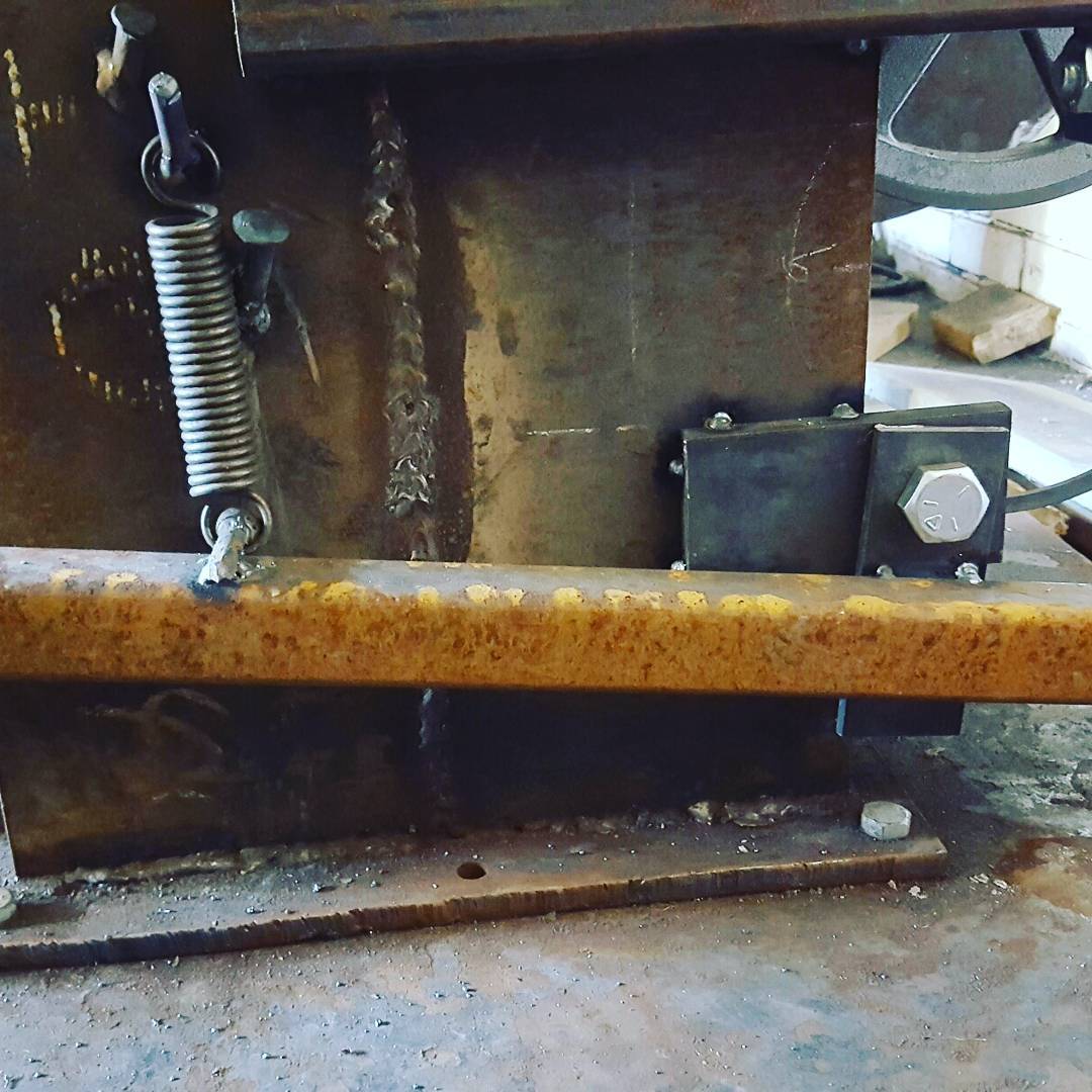
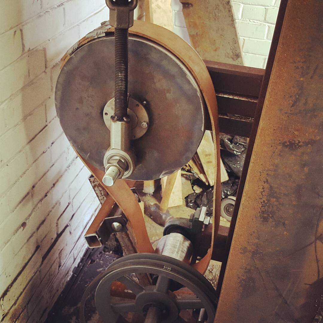
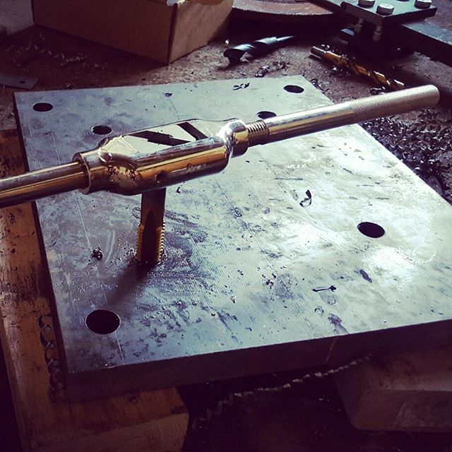
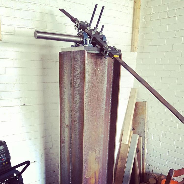
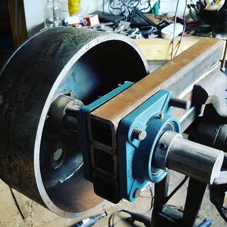
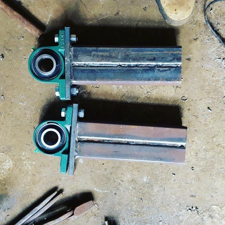
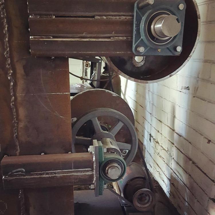
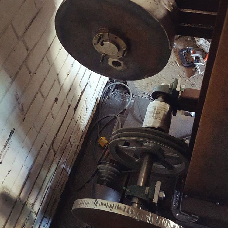
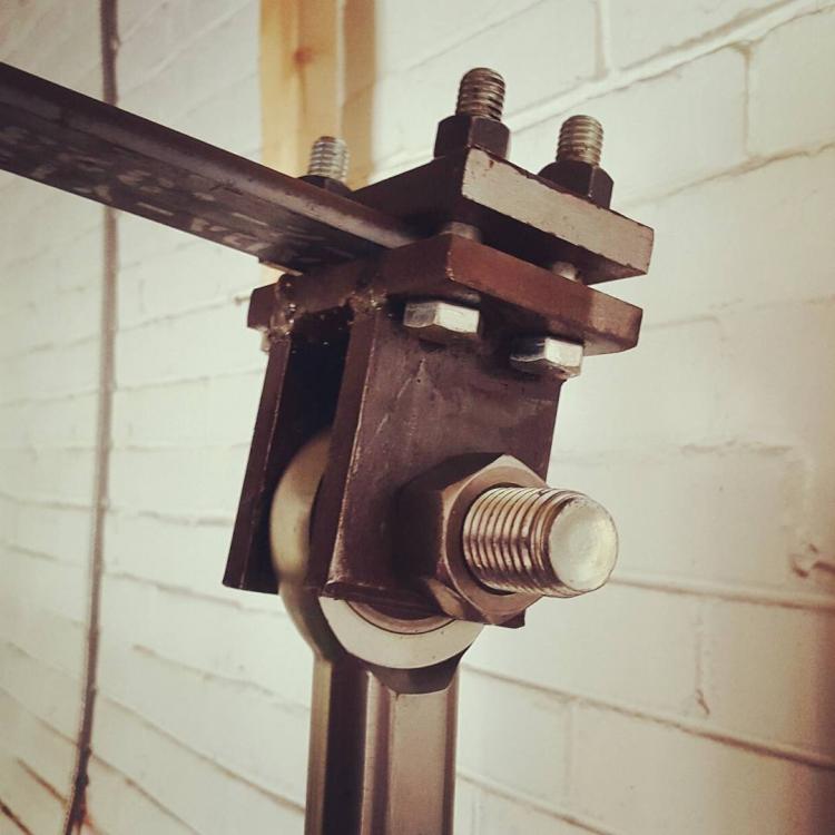
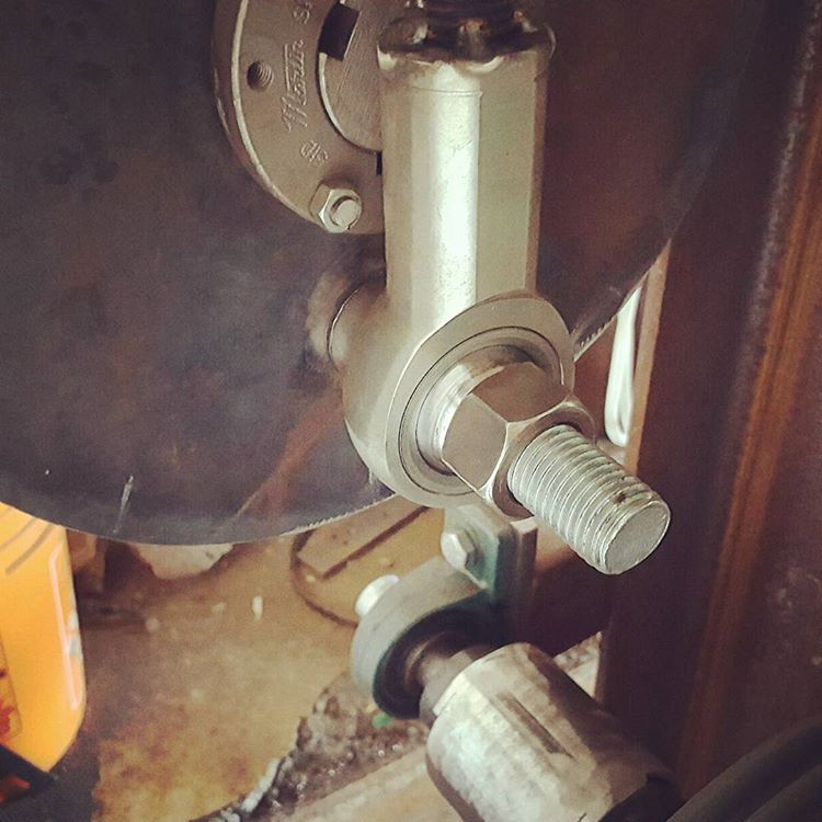
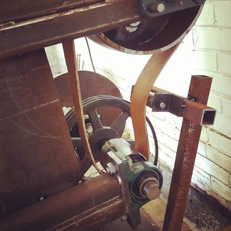
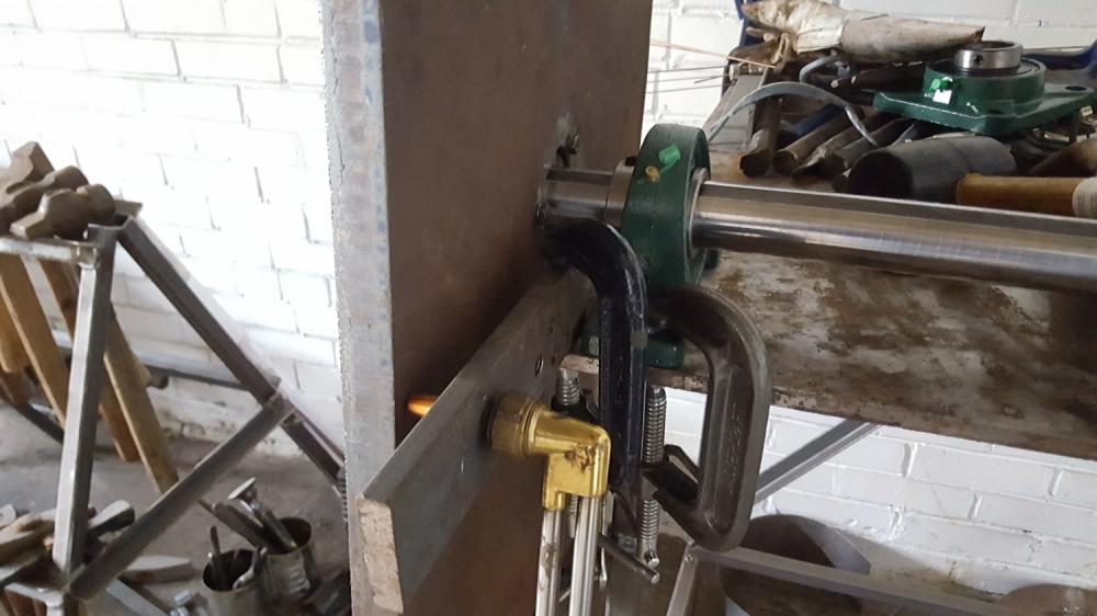
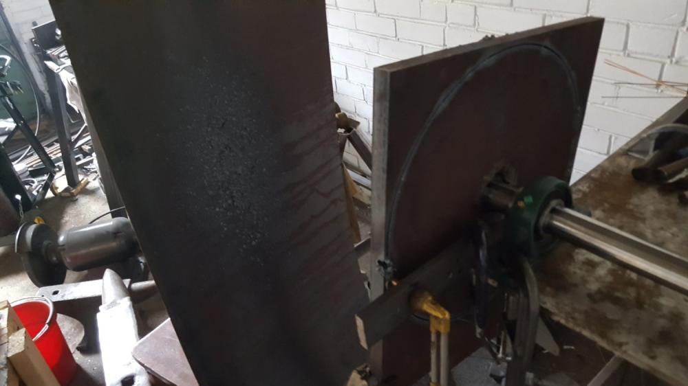
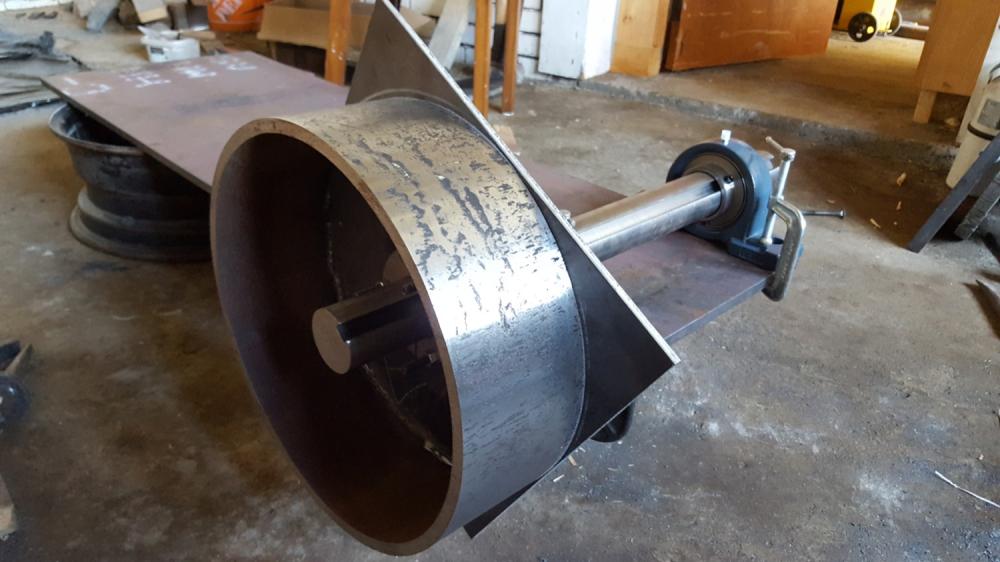
I was sidelined for a while by a noise/zoning issue. City bylaw officer showed up at my door stemming from noise complaint. Long story short, it essentially blew over. I did some sound proofing and the build continues. Top Pivot The pivot is 2inch pillow block bearings, attached with bolts to threaded holes in a top plate. The top plate bolts to the top of the mast with through holes. This will allow optional spacer plates to be inserted beneath to raise the pivot, per arftist's design. I'm also keen on being able to disassemble things if I need to modify or move. The ubolts are bent from 5/8 threaded rod. Drive System The bearing supports are fabricated from thickwall tube and clamped/spot welded to the frame; welds to be finalized at a later point after I'm satisfied that everything fits and works. I spun the jack shaft with a small motor and trued the flywheel with a flapdisc. It was already very close, just the kerf from the torch cutting. It spins true at 800 rpm with little to no vibration. Pitman Arm The pitman arm is 1 inch threaded rod with spherical rod end bearings on each end. The pin is a grade 1 inch grade 5 bolt that passes through a spacer to allow clearance and extra support. Treadle and Idler I machined an idler pulley from 1.5 inch thick walled pipe. I don't really know the range of motion necessary to give adequate tension, so the treadle construction is kind of an experiment, hence the spot welds until things are finalized. Bolts for treadle pivot, spring return. Flat Belt setup I positioned the idler to just touch the belt when treadle is up. Treadle down it jabs inward 4-5 inches. I cut the flat belt long and joined the overlap with duct tape while I get a feel for the tension required. I tested by manually spinning the jackshaft flywheel and engaging the treadle. I had used a flapdisc to put a light crown on both pulleys, and best I can see now tracking isn't terrible, but decided flanges on the idler and smaller pulley could help. The flanges were forged and welded.


-
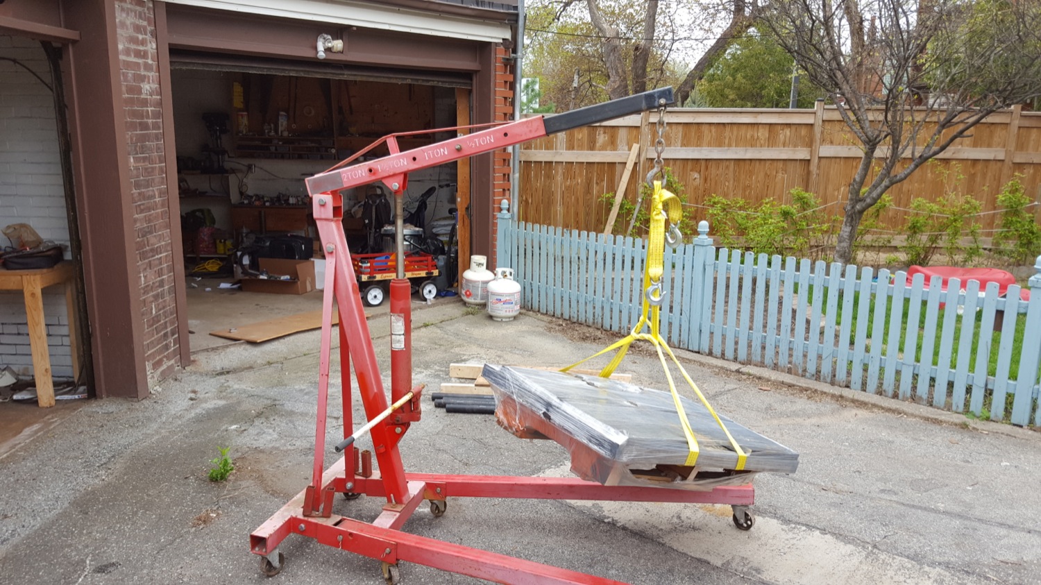
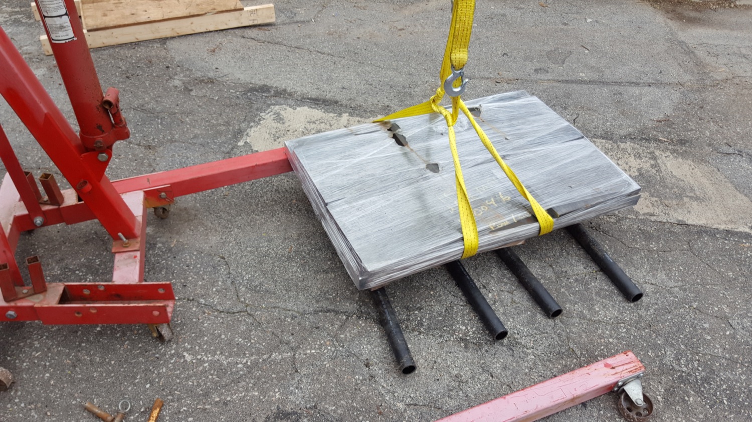
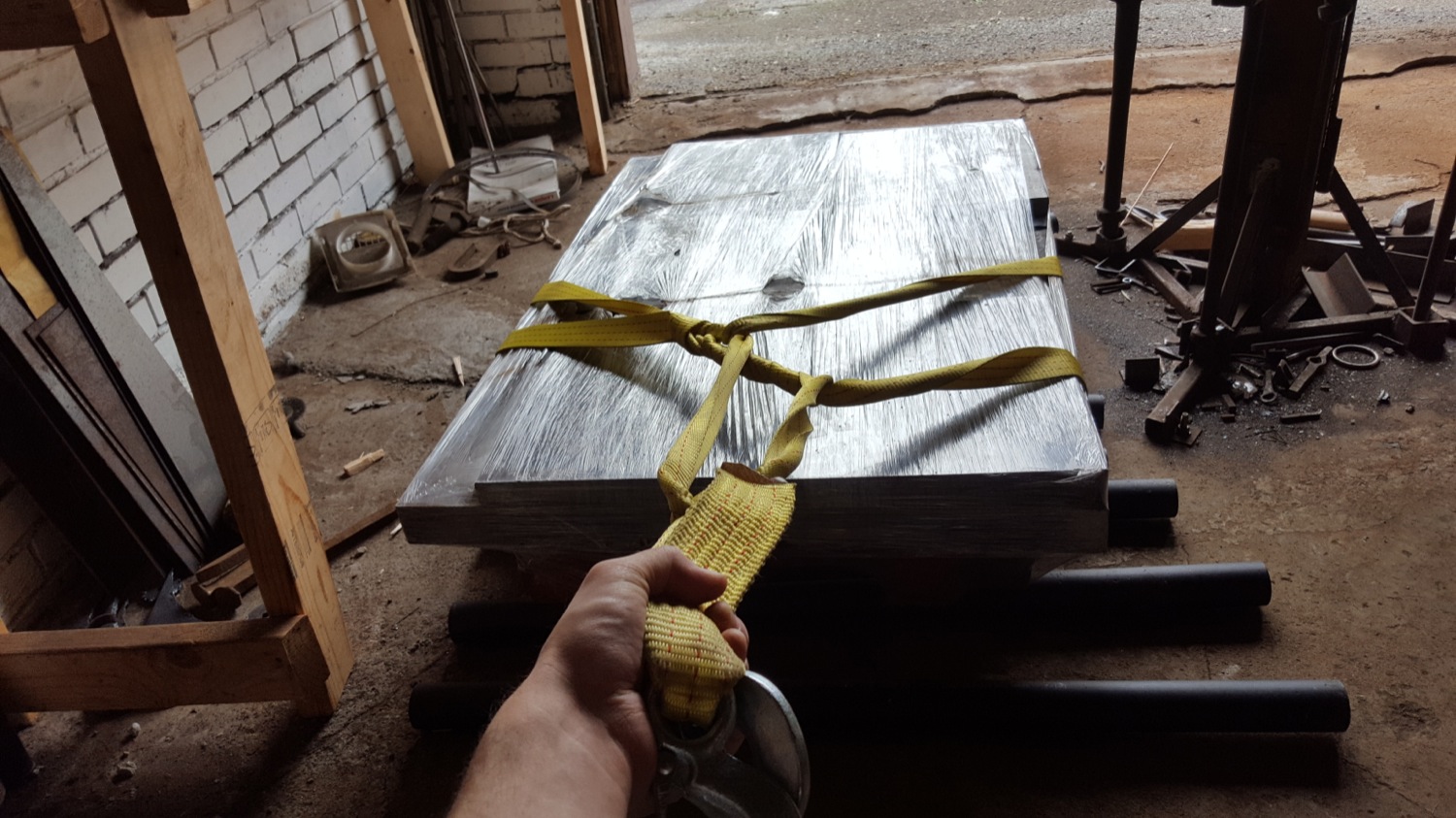
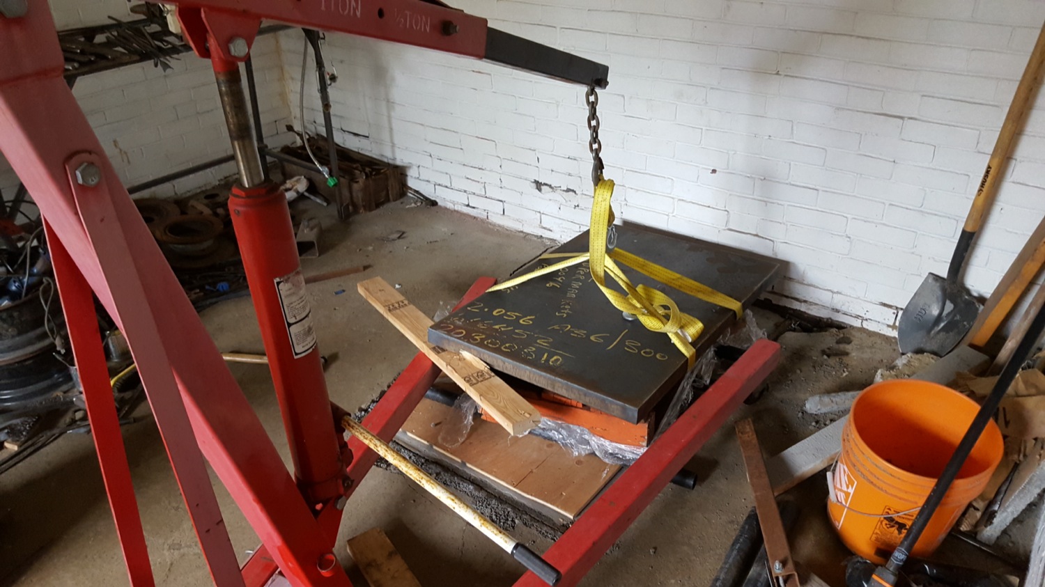
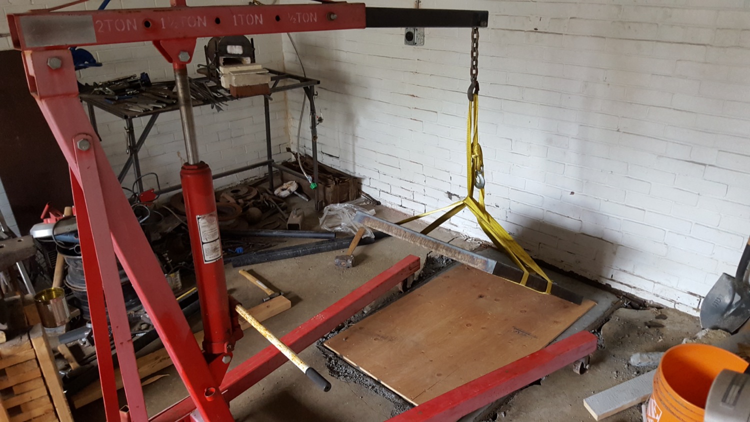
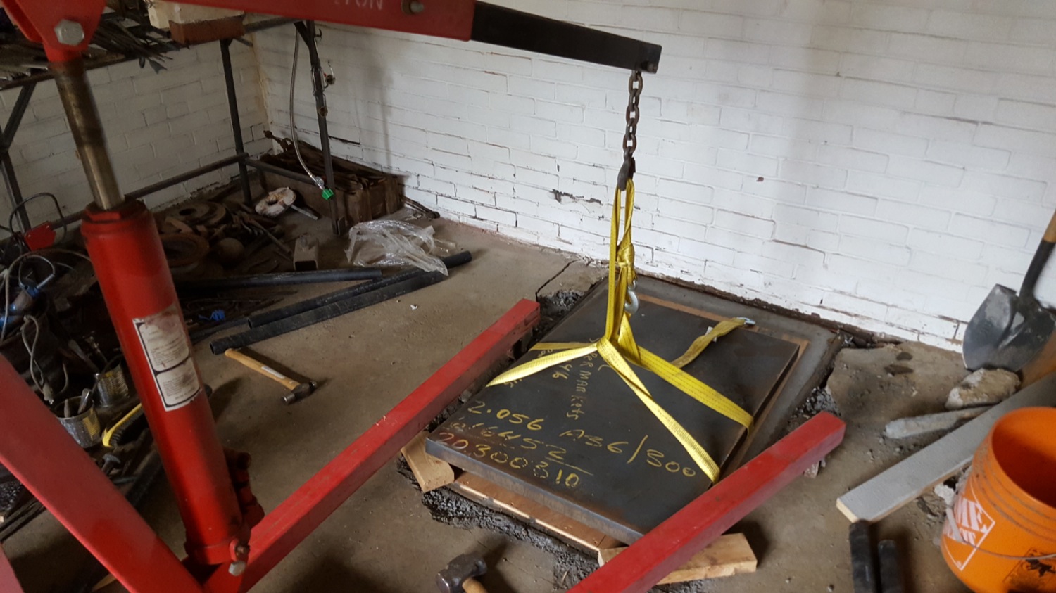
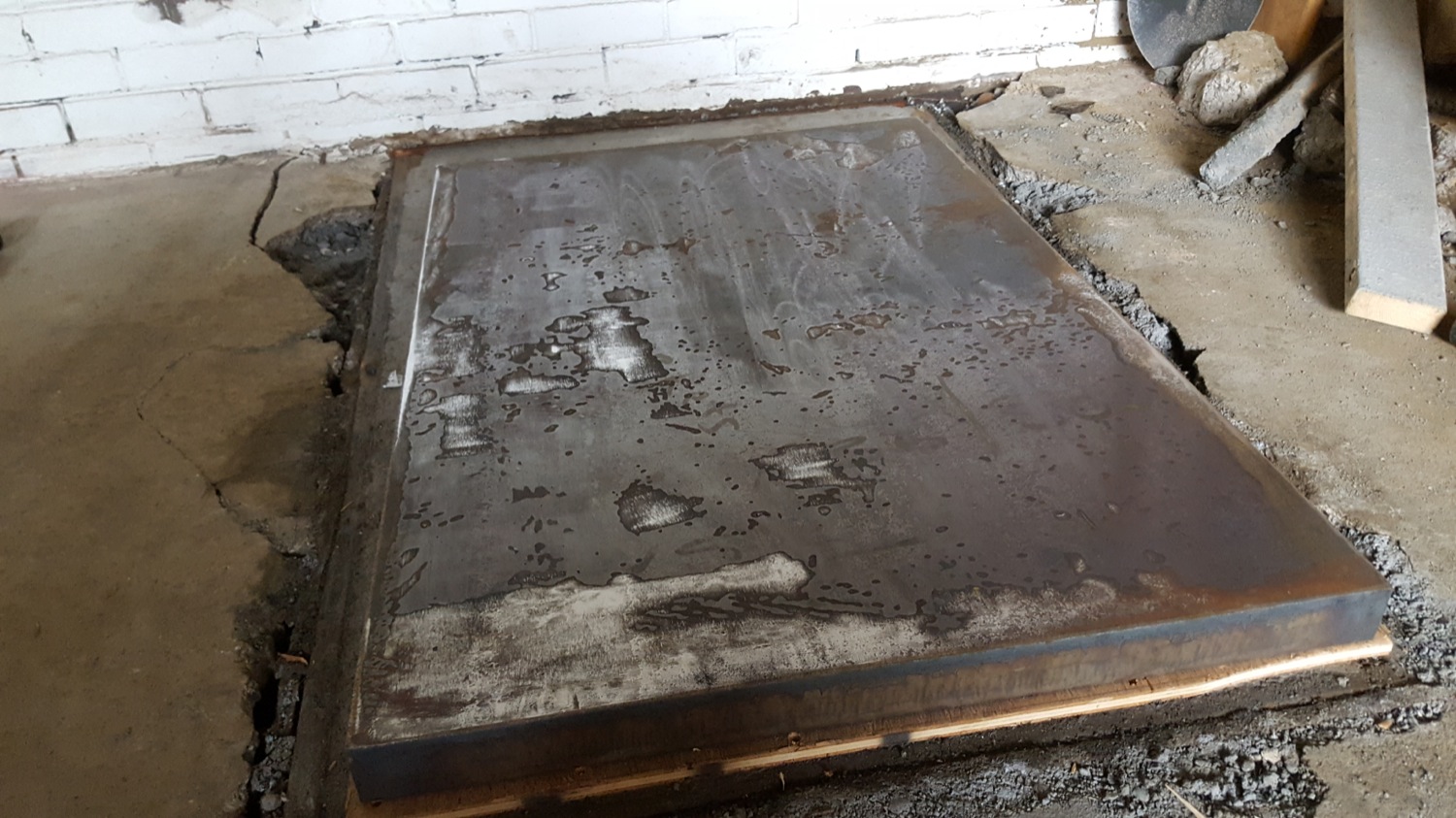
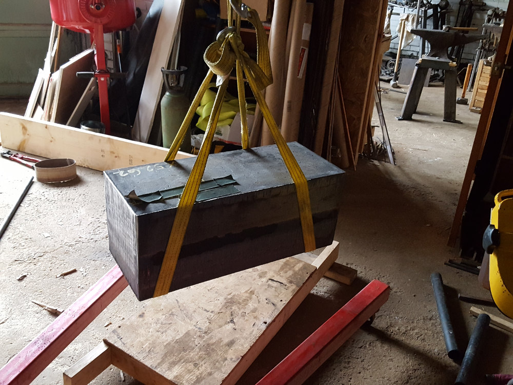
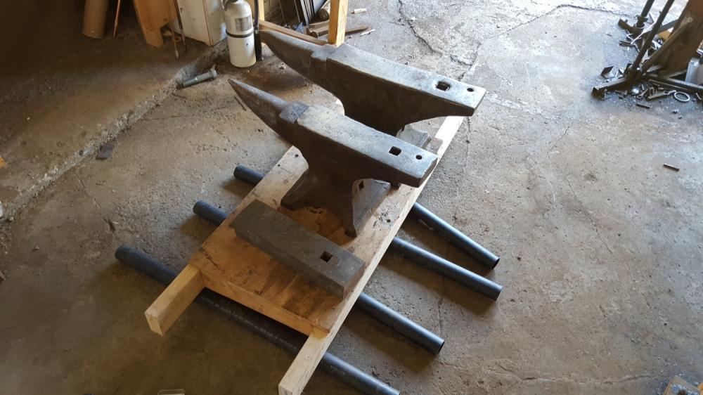
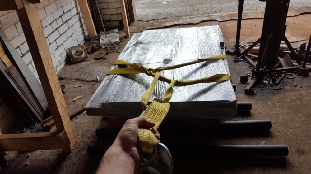
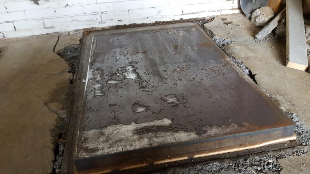
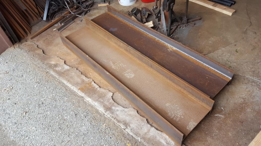
Unloading some heavy steel Had some large pieces of steel delivered today, notably a 2x28x42 plate weighing 700lb. I was responsible for unloading, and was a little nervous having never moved anything of this weight before. I prepared in advance by building a sled and testing it on 1.5" PVC pipe rollers carrying the heaviest items I have. Gratuitous anvil shot: Delivery came in a pickup truck. I was prepared with engine hoist and tow cable. The delivery guy was friendly and helped me rig the hoist. All went smoothly. Plate was on a skid so I didn't need the sled. There are some additional smaller pieces of plate bundled, so the total weight was close to 1000lb. Lowered it onto rollers and pulled it into the shop. Pretty easy on rollers! Reminded me of the strong man competitions where they pull an airplane. Concrete has been moist curing for 2 weeks so I decided just to put the plate in place. First a piece of half inch plywood, then rolled the whole skid on top. Used the engine hoist to lift just the plate, then removed the skid and rollers and set it down on 2 blocks, to allow removal of the tow cable before kicking out the blocks. Actually i used a hammer because I value my toes. It was a pretty satisfying sound when I tapped out the last block. Kathunk. Zero rebound movement, like in the cartoons when they drop the anvil on Wiley Coyote. Also part of the delivery were two 66" long w14@34 beams for the mast. These were pretty simple by comparison to move and unload. Overall I found the entire move wasn't nearly as difficult as expected. If it had been top heavy, fragile machinery it would be a different story. But big chunks of steel rig and roll easily. I didn't order steel for the anvil for two reasons. First, to test my abilities unloading, and second to see what kind of cut edges I have to deal with. The base plate appears to be CNC plasma/torch cut, and it's smooth and accurate. The beams and 1" plate pieces were saw cut, and not perfecting square. I'm choosing between laminating 1" plate vs a solid anvil. Laminating would be cheaper, but that's a lot of welding and grinding, and the plates will not be perfectly aligned to begin with. Might opt just to buy a solid piece, now that I feel more confident unloading 1000lb. Starting to look like a hammer now.


-
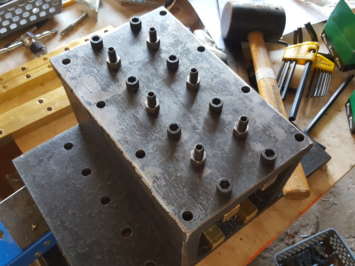
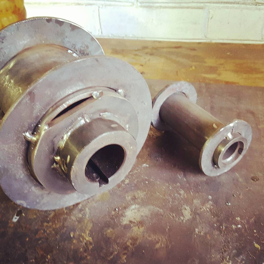
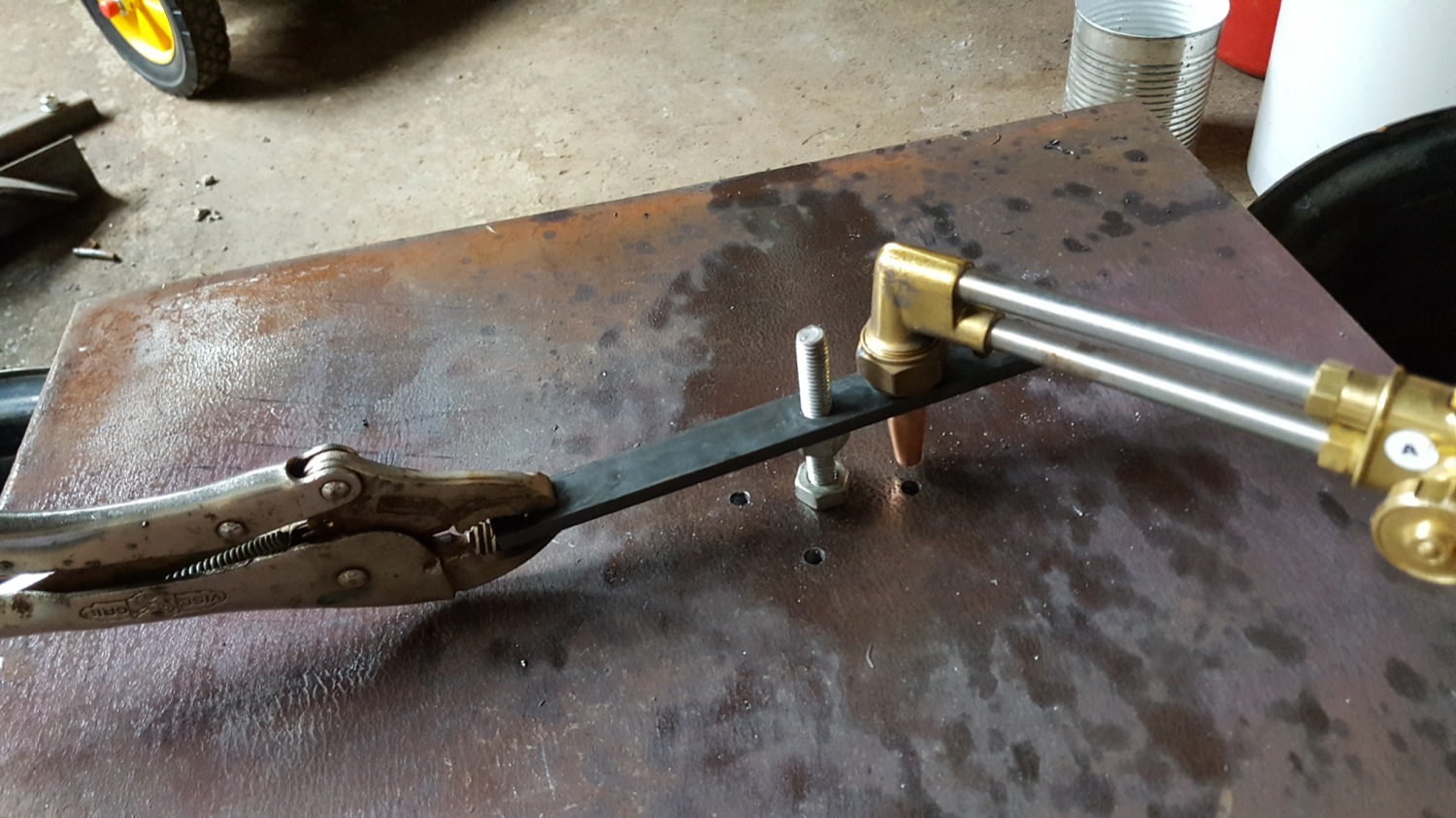
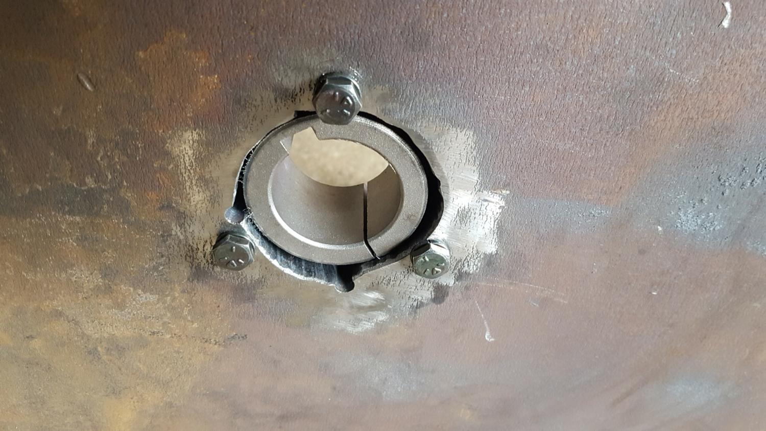
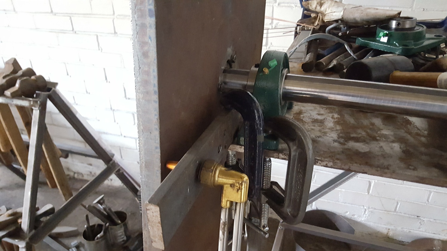
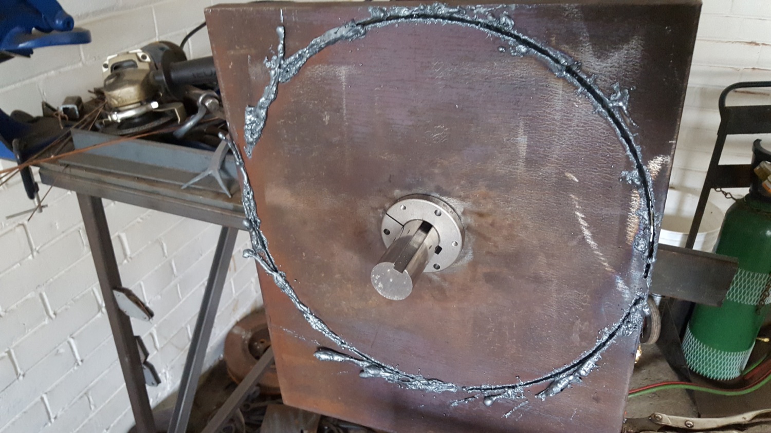
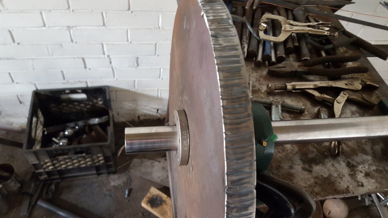
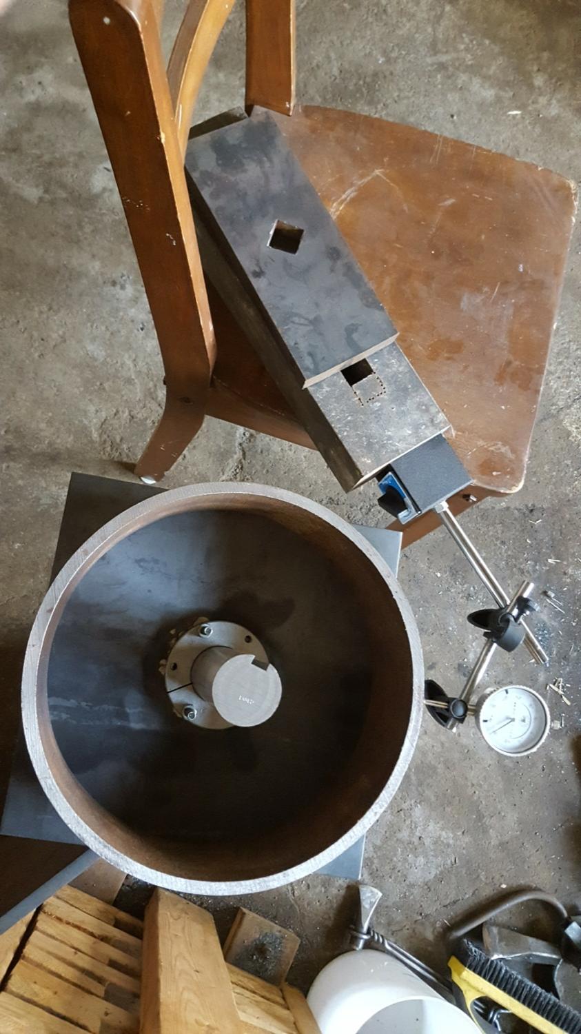
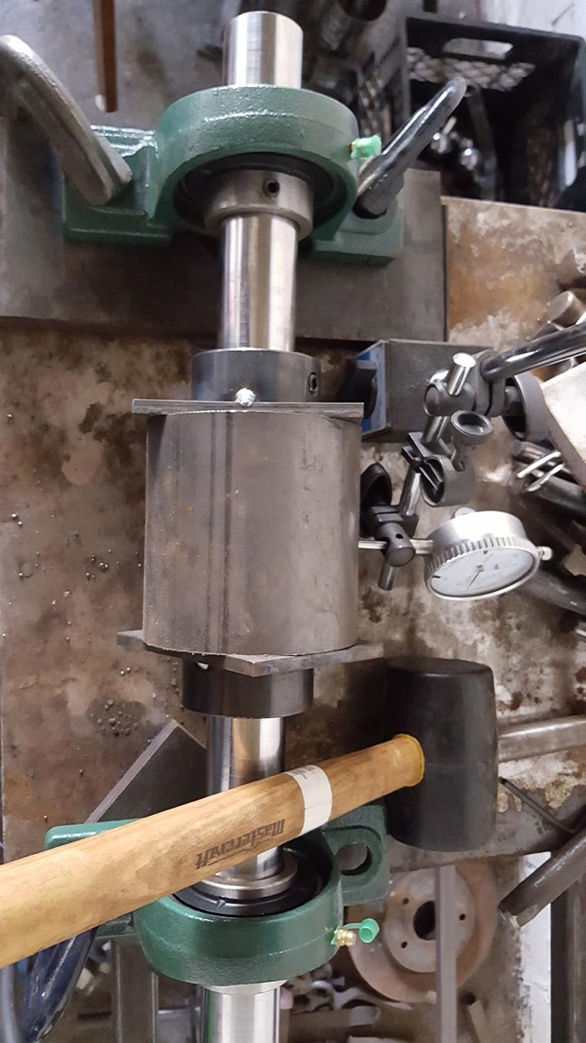
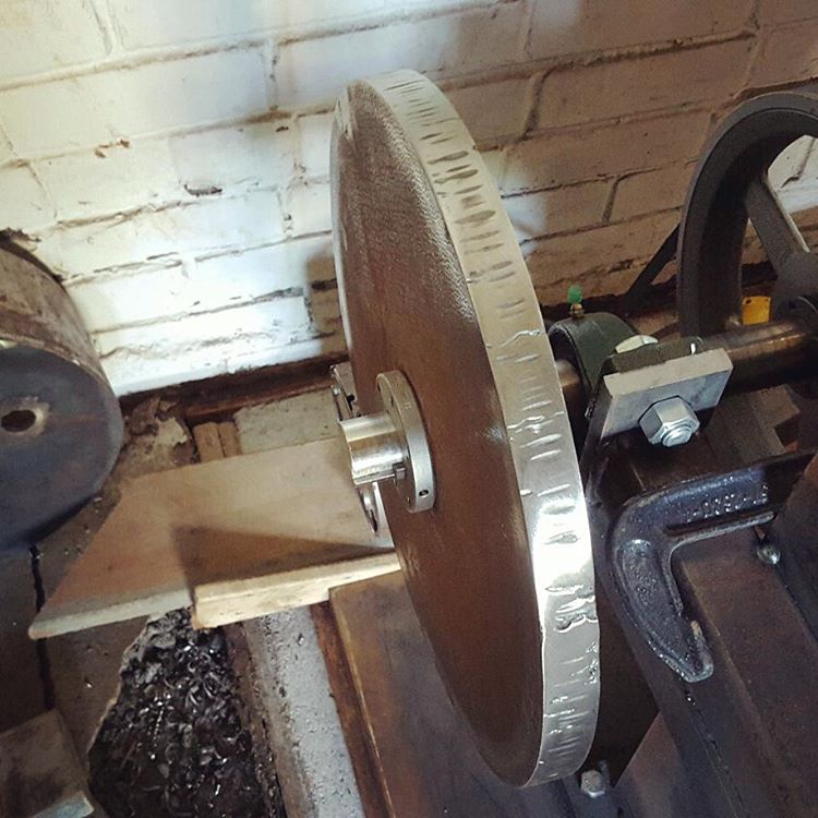
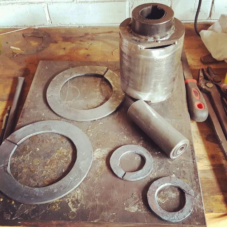
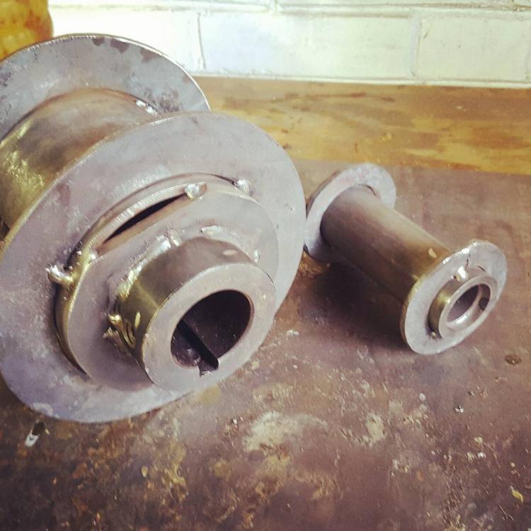
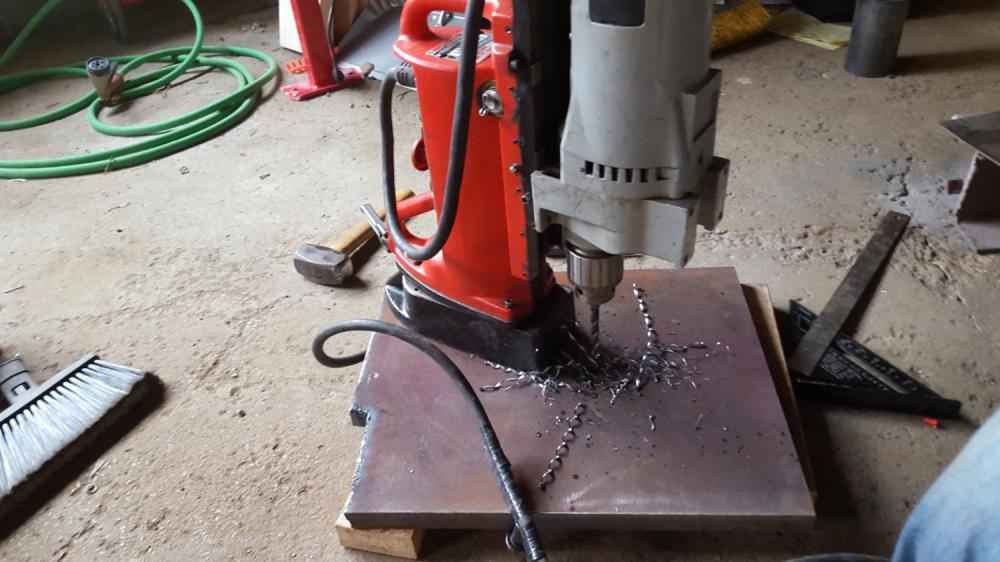
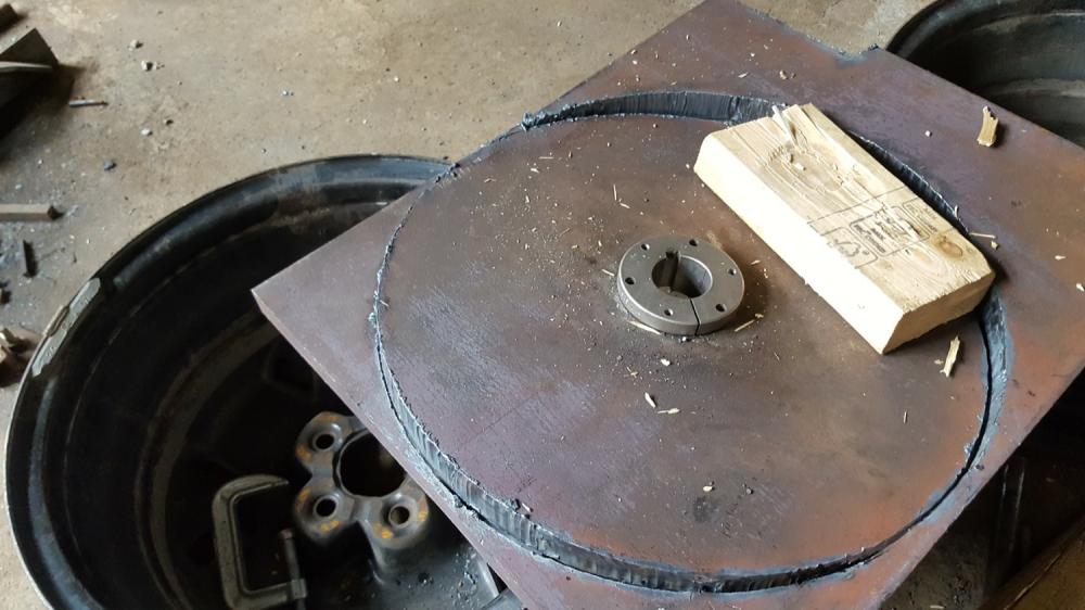
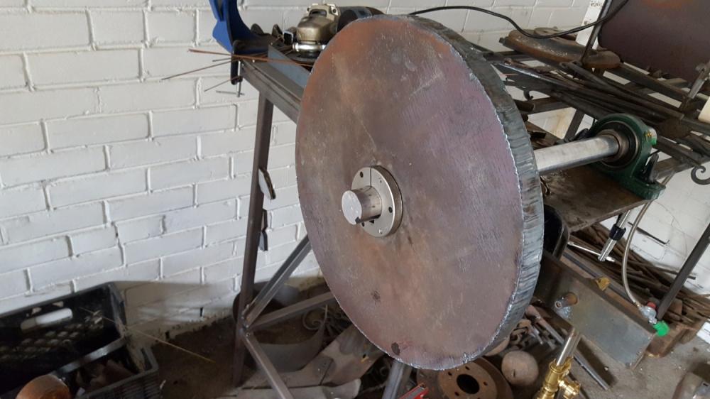
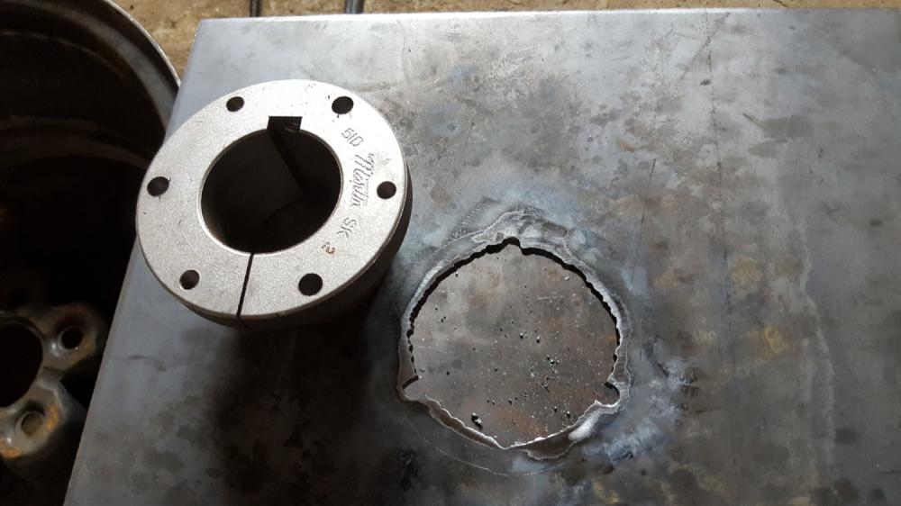
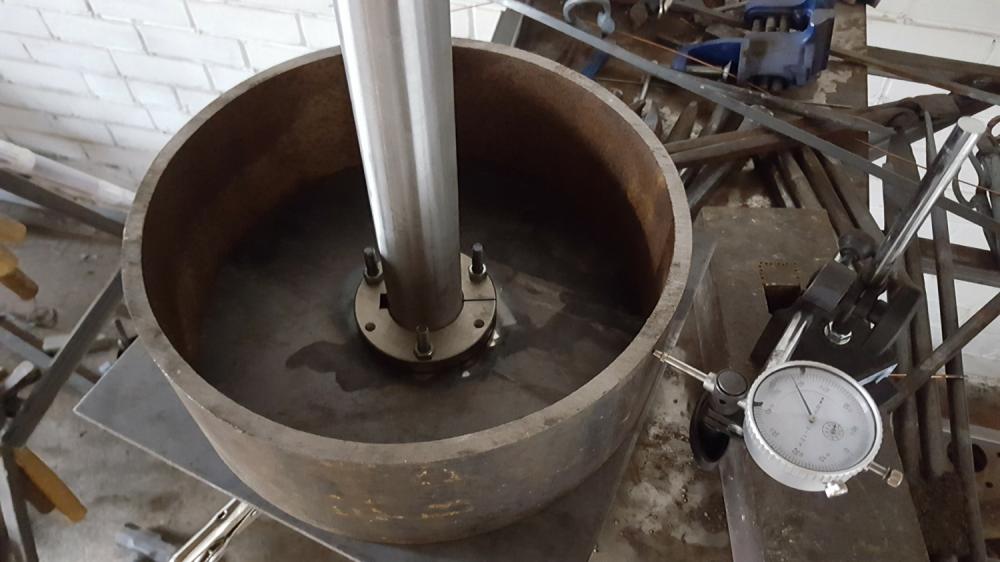
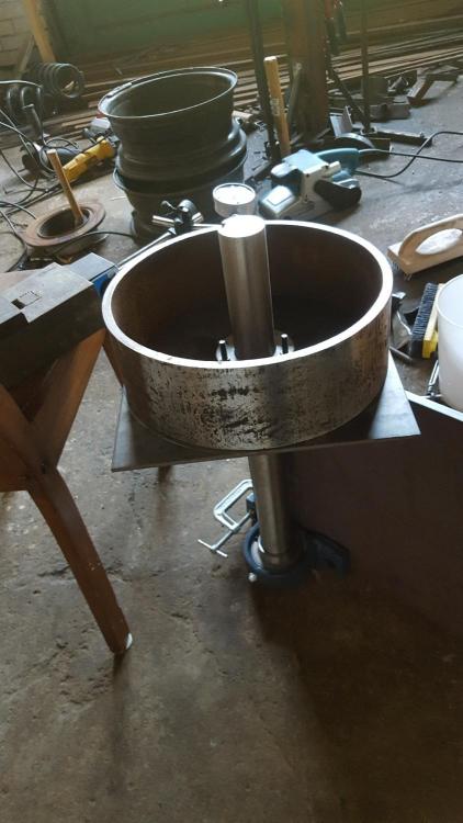
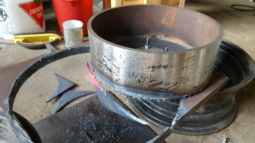
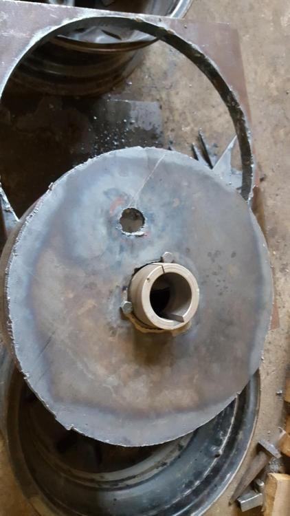
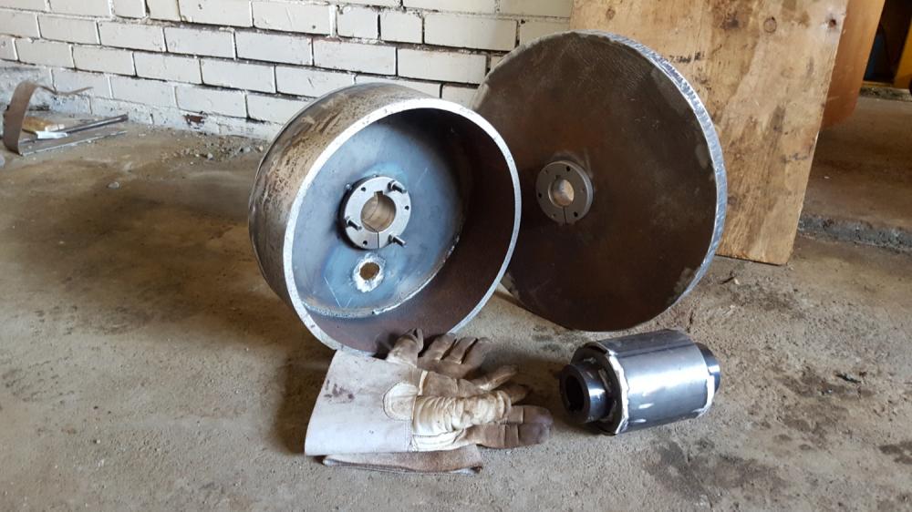
Fabricating flat belt pullies and flywheel My hammer will use a flat belt clutch (4x4 and 13x4 pulleys) with a pre clutch flywheel (16" diameter, 60lb). I initially puzzled over how I would acquire these parts: 1. I could try to scrounge for them, but that would take forever and probably wouldn't find my intended dimensions, introducing compromises/contraints in the design. 2. I could buy the parts or pay to have them made. But then I will only have those parts. If they wear out, or need to be redesigned I'll have to shell out again. Finally I realized I should just give a go at fabricating them. I wouldn't necessarily recommend this.. I chose this approach because this is a kind of personal DIY journey. Time consuming mistakes will be made, tools/raw materials will be purchased, but in the end I'll (hopefully) have the parts I need, and (definitely) will have gained skills, experience and tools that will surly be useful in a blacksmith shop. Plus, it's really fun. So I bought some plate and pipe and got to work. I had a first failed attempt at the 4x4 pulley. I torch cut a hole in some 1/8 plate (too thin, warped) for a weld-on hub, then attempted to weld this and the pipe together concentrically just by laying out with a ruler. Of course it didn't work. When I got to spinning it on an axle it was noticeably out of center. I tried truing with an angle grinder while spinning at low speed. The surface got smoother, but the part did not get much more concentric. The grinder just follows the surface rather than selectively removing the high parts. Since then I've done the right thing: acquired a 10" x 18" lathe and spent some time learning some machining basics. That's a whole story in itself, but suffice to say it will help with the 4x4 pulley (as well as rollers, idler etc), but the 13" pulley and flywheel still needed to be fabricated. Next attempt was the 13" pulley. Drilled a few holes then torch cut rough hole in 1/4 plate for QD bushing. Filed holes for bolts and secured bushing. Mounted a bearing and axle vertically, placed a slice of 13" pipe on the plate and rotated with a dial indicator while adjusting for concentricity. The jig was using only one bearing and had runout, so switched to a setup with two spaced bearings. Found the low point on dial indicator, tapped with a mallet. Got it to within about 10-15 thousands before welding in place. Torch cut the corners of the plate off and ground smooth. Rough cut a 1" hole at 3.5" off center for the crank pin. Mounted it horizontally, and lighty sanded it with a 4" belt sander while turning. As it stands, pulley is not crowned, but I will later attempt to grind/sand a taper on the edges. Here's some shots of similar process for my 2nd attempt at the 4x4 pulley. Cut holes in plate and welded on the hubs. Set everything up on bearings and axle. The pipe is held by friction between the two plates, adjusted by tapping with mallet while reading the dial indicator. Tack welded in place. Sawed of the corners. I'll finish it up on the lathe. The flywheel is 15" diameter cut from 1 inch plate. I started by drilling a few holes. (Note: I pickup up a nice used mag drill around the same time I started this, and I'm sure glad I did. I doubt much of this would even be possible without it, at the very least makes life sooo much easier ) Rigged up a circle jig for the torch. The circle jig didn't work incredibly well, but it was good enough for the mounting hole. Drilled some bolt holes and secured the bushing. Next came the fun part. I wanted the flywheel as true as possible without requiring machining/ginding. I thought about different ways to do this. I decided a circle jig wasn't going to cut it (hehe) and opted instead to keep the torch stationary while spinning the workpiece. Mounted the plate on axle/bearings. Torch tip fits snugly into a half inch hole in some flatbar clamped to the table. Checked everything was steady, did a test movement run before lighting the torch. There was a lot building up to this moment. While the sparks were showering, have to admit I got a pretty big rush. Oxy-propane torch is powerful tool, and wielding it to cut a wide perfect circular arc through inch thick plate like a hot knife through butter was amazing fun. Had never torch cut material of this thickness before. Removing the circular fom afterwards took longer than the cutting. Had to chisel in some places and beat on it for a few minutes to dislodge. End result: 15.5 diamter, about 55lbs. It will spin at about 650rpm. And here are the machine parts. Took some time, but feels worthwhile.


-
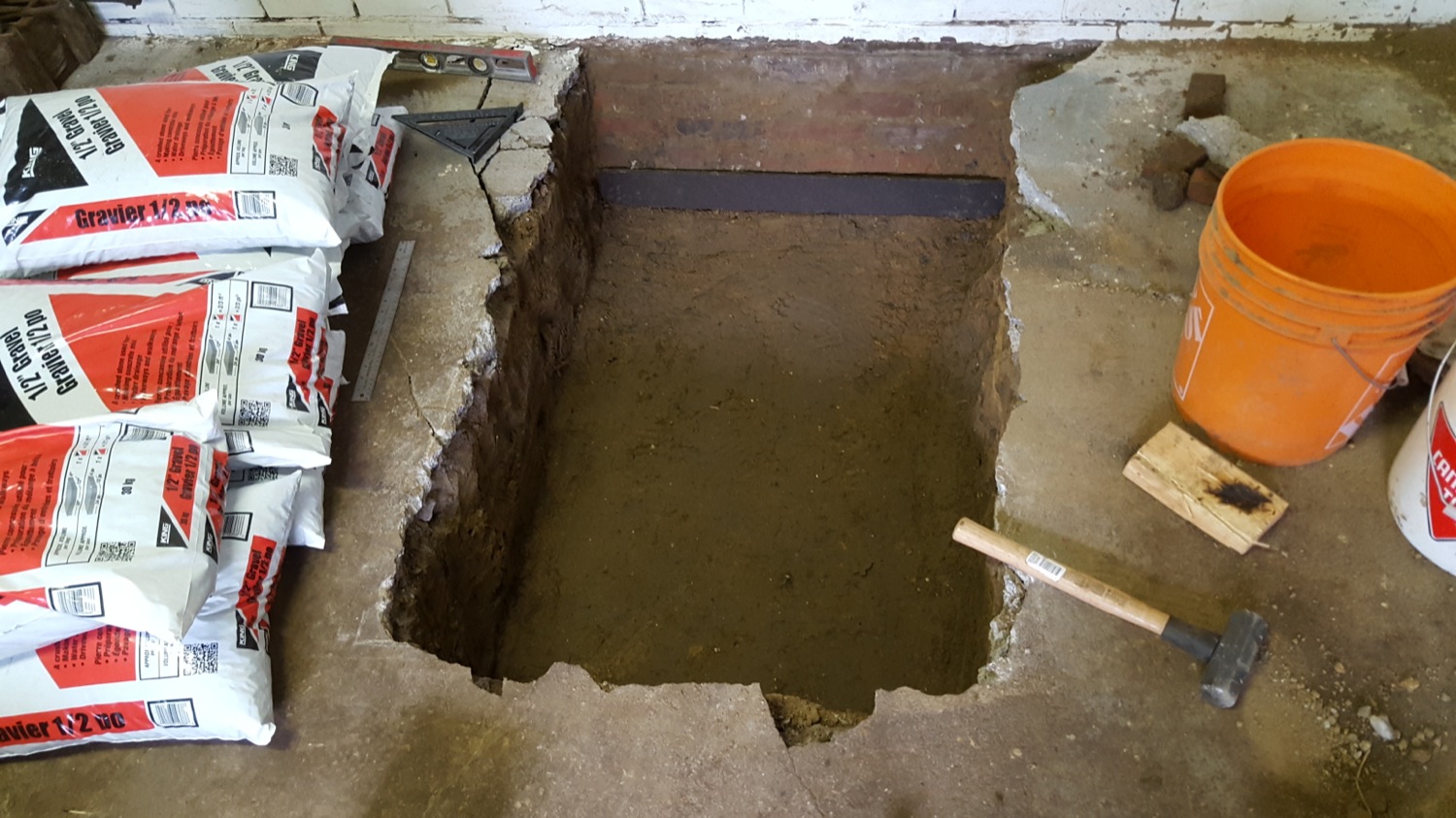
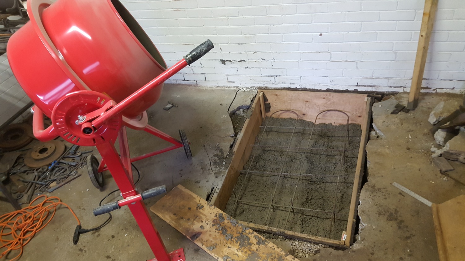
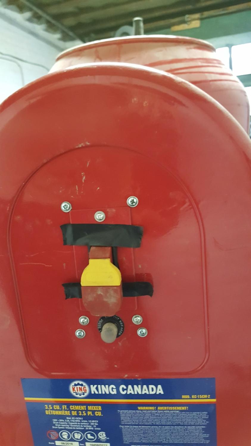
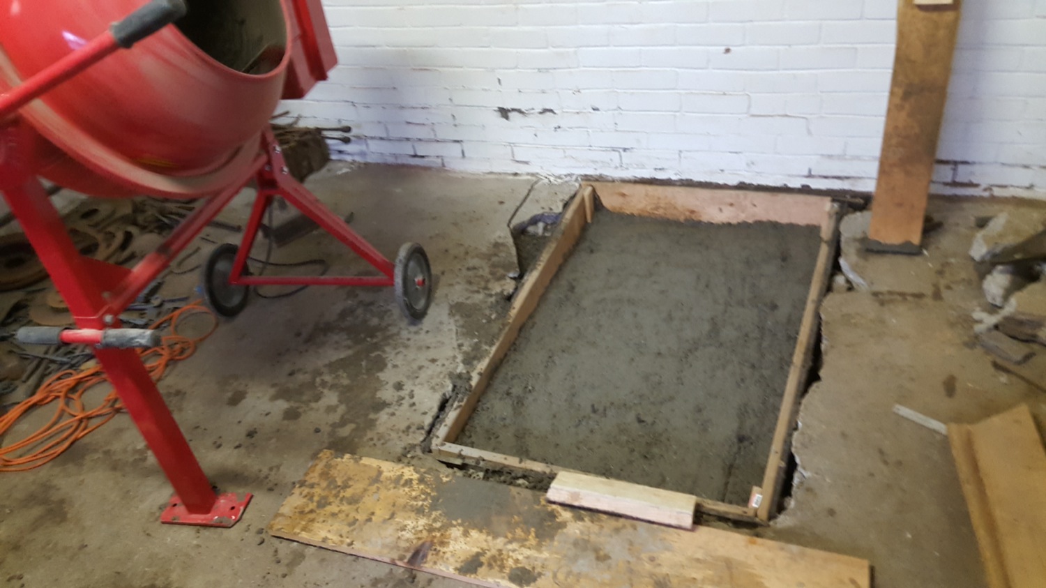
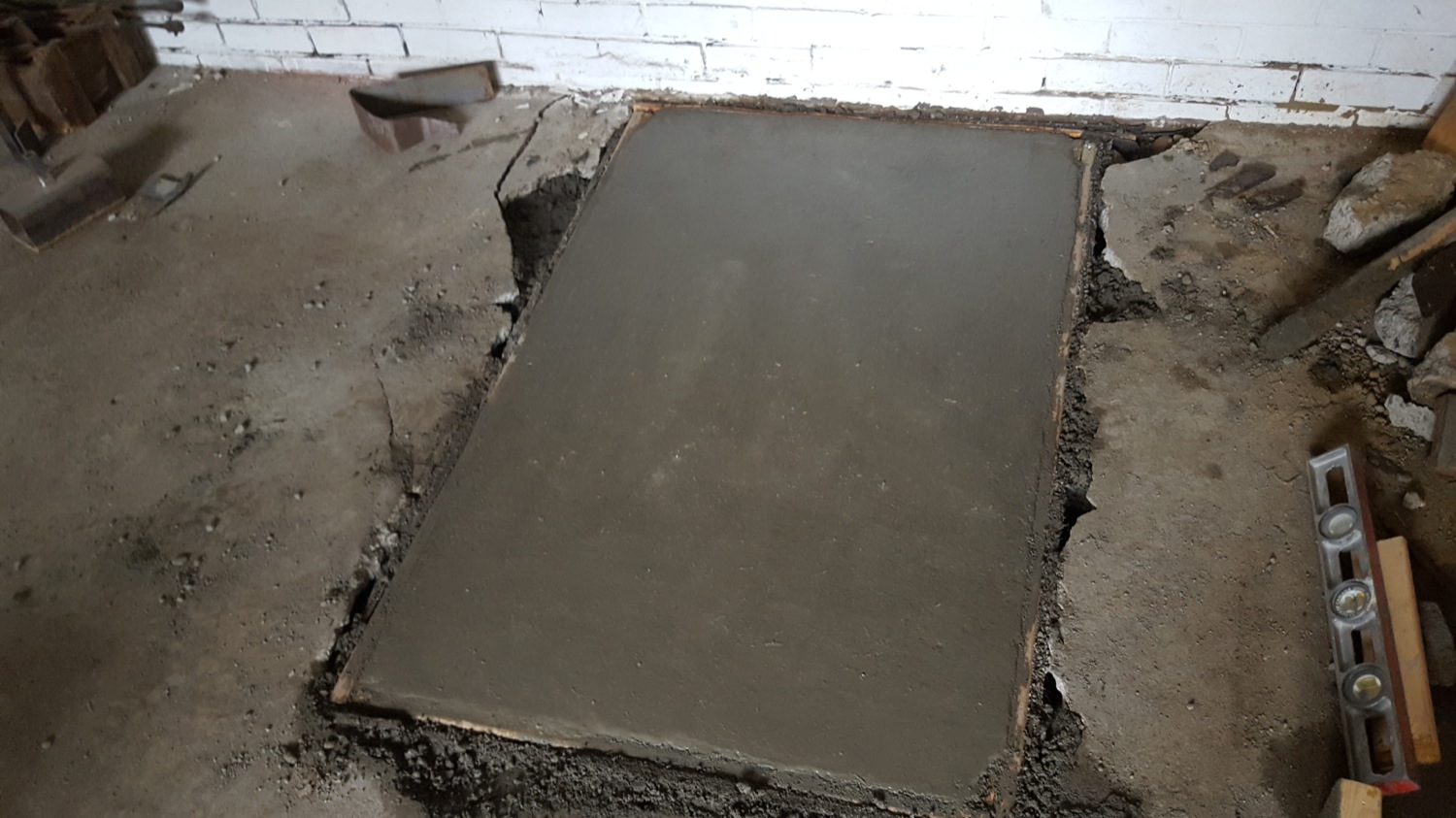
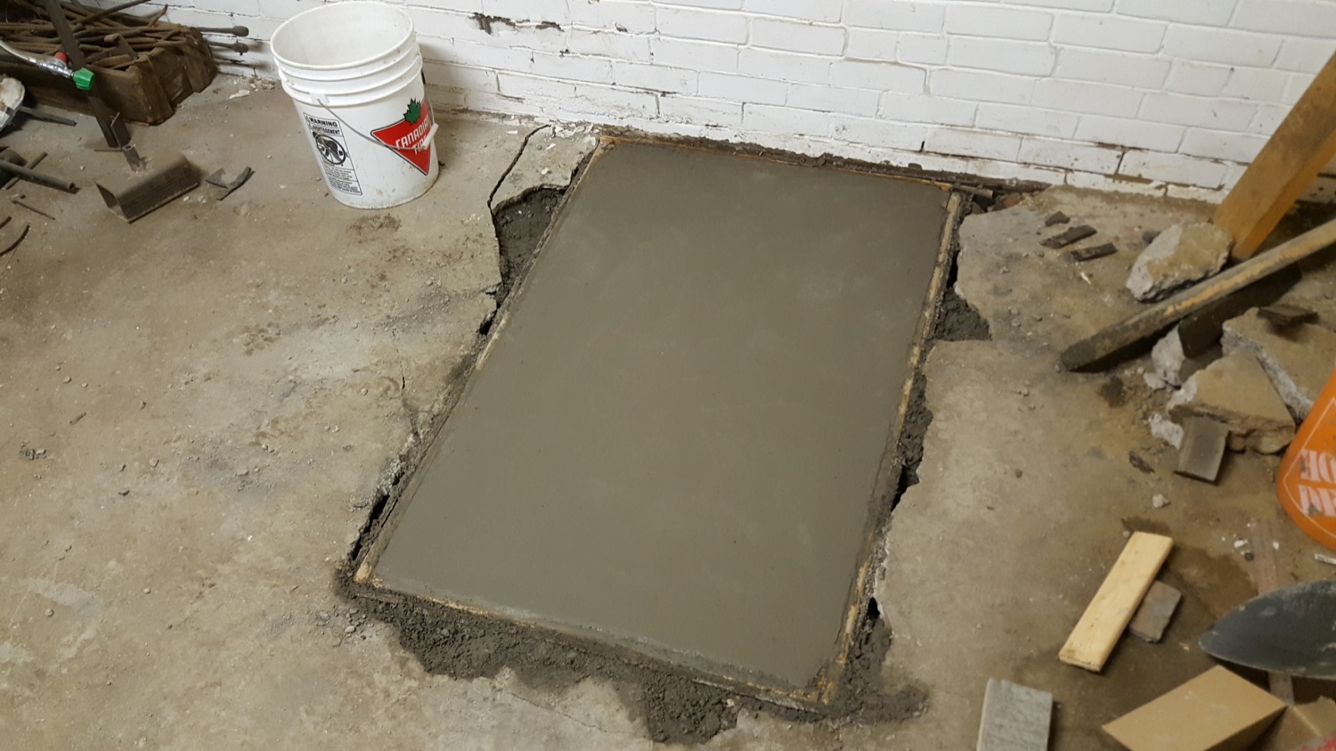
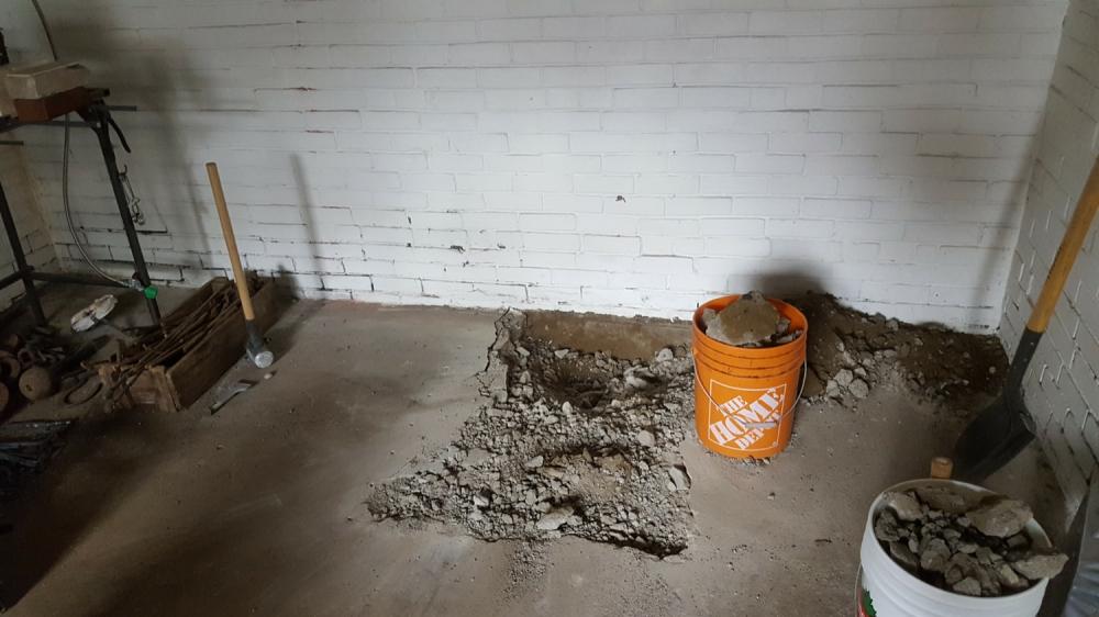
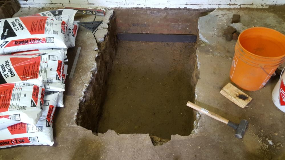
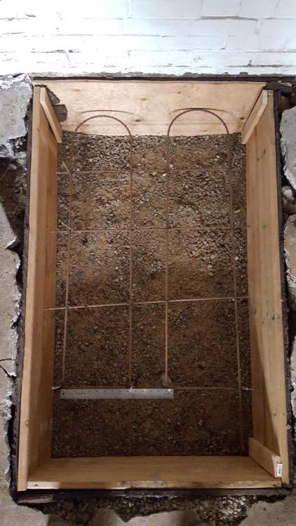
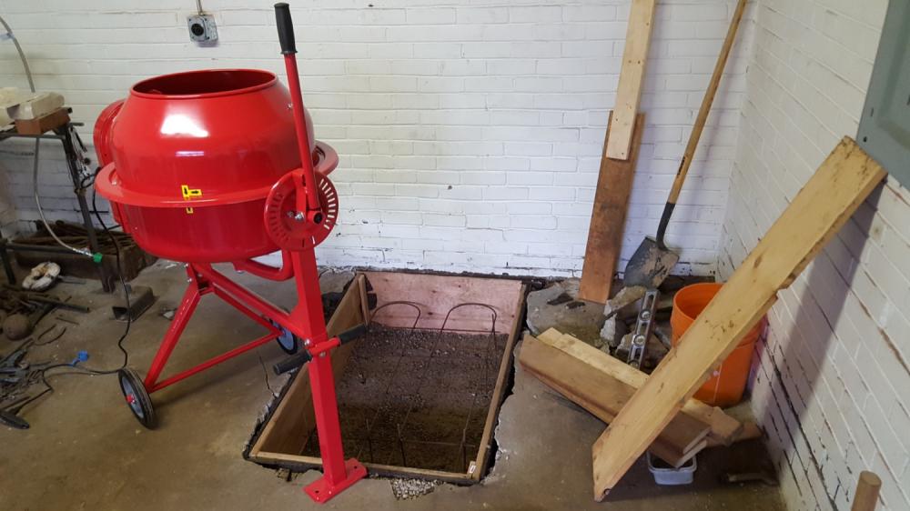
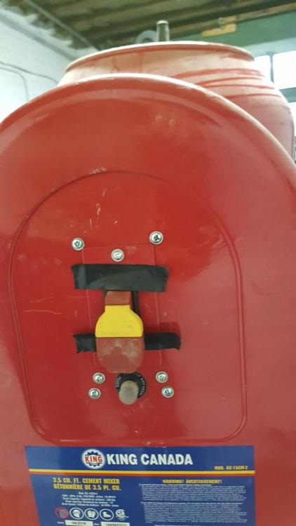
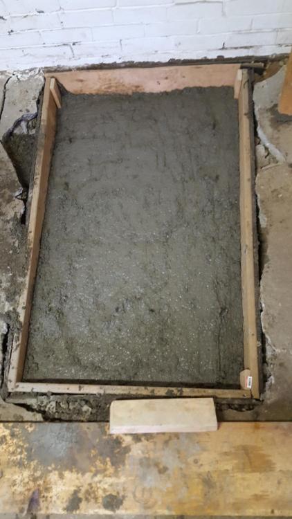
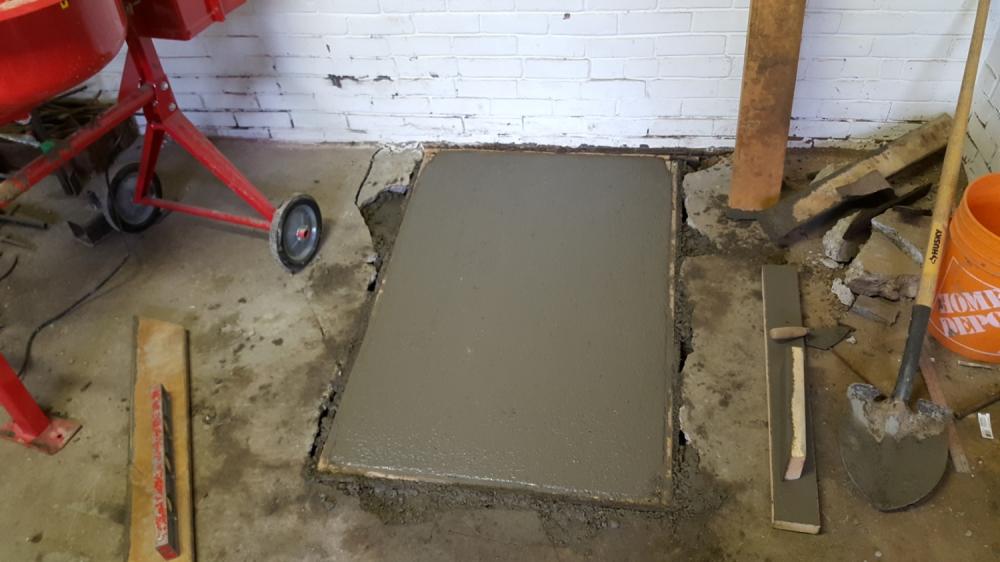
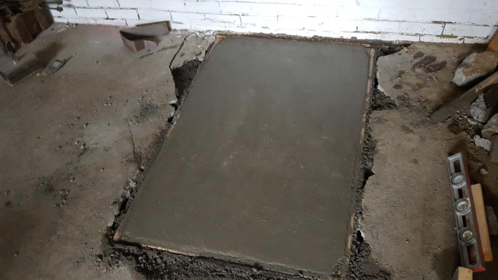
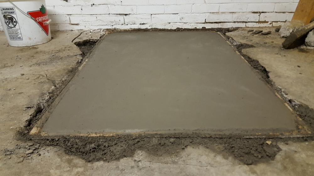
Progress! Pouring the foundation In the last couple of weeks, I prepped and poured the power hammer foundation. Although probably not necessary for a hammer of this size, I want to do all I can to minimize vibrations as I'm in a residential area: heavy isolated slab of concrete, 2 inch baseplate, and 15:1 anvil/head ratio. I started by choosing the position of the hammer. Roughly in the middle near the back wall. Dies will be on a diagonal to maximize working length. The floor in my garage is very old 3 inch concrete, cracked in many places. Rather than renting a concrete saw, I just drilled holes and broke it up with an 8lb sledge. That took a lot of effort. Good striking practice, part of my exercise regiment. Benefit was that there was minimal dust (compared to a dry cut saw) or gas fumes. Dug down 16 inches, compacted the dirt. Filled the bottom 4 inches with gravel. Lined the sides with wood and fiber expansion joint. Placed a 'rebar' cage (some scrap twisted square bar). Cavity is now roughly 30 x 55 x 12 inches. Debated putting in an assembly for T-bolts, but decided to just keep it simple. If I even need to bolt the hammer to the foundation, I'll expoy in some all thread. Likely will probably just attach some pins/supports to keep the hammer from moving around. Debated between renting and buying a concrete mixer. Needing to maximize flexibility in scheduling : when it came time to pour, don't want to waste time driving to/from the rental store. So I went ahead and bought the harbor freight equivalent here in Canada of a 3.5cf mixer. Assembly was not too bad. Got everything ready the day before the pour. 30 60lb bags of high PSI premixed concrete, mixer in place, hose, compacting and forming tools. Note that I've never done any of this before. I have to plan things well to wrap in time, as I only have max 5 hr blocks of time before picking up kids from preschool. I calculated that should be plenty of time. Day of the pour, everything seems to be working well. Mixing with minimum water for maximum strength. First 10 bags take less than hour. Then the mixer quits! I keep calm and troubleshoot. The on/off switch has vibrated out of its housing and come apart into pieces. Fortunately I was able to fix it relatively quickly. What a bummer that would have been. Rest of the pour went fine. I had worried way too much about having the wooden form perfectly level. Turns out that mass of concrete will do a good job of leveling itself out. Smoothed it with a 2x4 and then as it hardened with a small trowel. In the end was 24 bags so upwards of 1500lb. For the past 7 days, I've been keeping it wet and covered with plastic. Base plate won't come for another couple of weeks, so will keep moist curing until then. Progress feels good! I've never worked with concrete before, it was pretty fun. Definitely a work out doing it on your own, but for someone who spends most of their time in front of a computer, it's great to be doing something physical, working with real materials and tools. More to come.


-
Question regarding spring deflection: to design dimensions, I need to know how much clearance above and below the ram guide to factor in for stroke plus spring deflection. I tried calculating it theoretically, but from others experience, how much overshoot can I expect? 5/16" thick, 2" wide. Main leaft 40" long, sandwiched between two 20" lengths. 7 inch stroke (3.5" from center of pitman crank) I calculated the spring constant to be about 14000 N/m. For a 50lb at 220bpm, I calculated the force on the ends of the spring during normal operation to be about 1200N, which would mean 3.5" deflection.
-
Thanks for the feedback guys. I'll likely reconsider fabricating the pulleys and flywheel. Biggundoctor my automotive knowledge is limited.. i had dismissed vehicle flywheel as too small/light. I suppose I could stack a few of them. I calculated that a 60lb disc shaped flywheel (1"x16"diameter) at 800rpm stores 2000 joules, or 2.5 horsepower seconds. Not sure exactly how that behaves in practice, but seems like it's in the ballpark.. flywheel energy could theoretically replace the 2hp motor for a second. Frosty, point taken regarding it being more trouble than it's worth. But then again, one could argue building a power hammer is more trouble than it's worth I might be stubborn and experiment anyways, because I find it fun/motivating, and because I'm at the point that I can still learn a lot from the process, regardless of the outcome. In any case I'll share the post-mortem here. I'll definitely also post photos of the build in general. Ptree, not sure if I understood completely, but are you using a 2nd tire as a flywheel pre-clutch? I want to try to avoid the tire clutch mechanism that has the motor directly driving the wheel.
-
I don't have a lathe, but my plan was a makeshift "lathe". Turn them on an axle and crown the edges with an angle grinder/flap disk. Same for the flywheel. Torch cut 1" plate with a circle jig, then spin it and grind it true as possible. Not a good idea? Otherwise I'll find some one to help with machining. Besides the previous thread, do you have any other photos or videos of your hammer arftist? Would love to see it in action.
-
Thanks for the feedback. I plan to use flat belt, for sake of smooth control. Although V-belt components would be easier to source, does not seem ideal in a clutch mechanism. I plan to fabricate any pulleys I can't source from pipe, plate and weld-on hubs. I'll use 4-ply cotton/rubber from McmasterCarr. What's the width of your belt? 2.5" would seem adequate in my case.
-
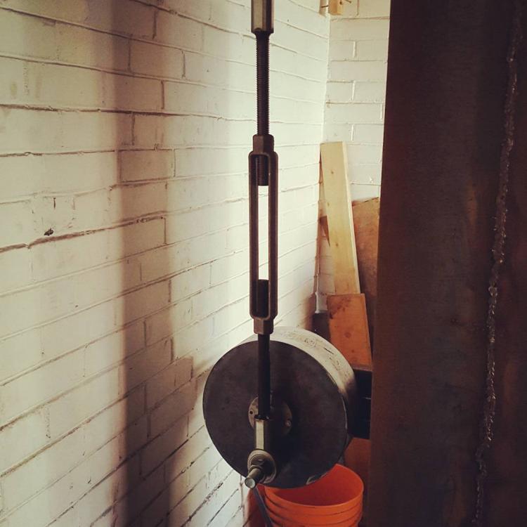
Hello I'm planning to build a guided helve hammer with preclutch flywheel, similar to arftist's: My goal is 50lb tup, 220bpm. I want it to be stout, efficient and minimize transmitted vibration/noise. Cost is important, but not paramount(I'll be buying new parts as needed rather than scrounging forever). In case of a later increase in head weight, I don't mind overdesigning some parts. I'm trying to get an idea of how beefy the mast and drive systems' bearings/shafts need to be for 50lb tup and how that would change for say a 100lb tup. Here's the 50lb design parameters. Feedback appreciated! Pivot: 2 inch diamter shaft and pillow block bearings. Push rod: 3/4" round (or 1" thick wall pipe?) with 3/4" turnbuckle Push rod bearings at bottom and top: 3/4" spherical rod end bearings. Pitman crank: 14" diameter, 0.5" thick Pitman bearing/shaft: 1.5" diameter Intermediate Jackshaft diameter: 1" Flywheel: 16" diameter, 1" thickness Anvil: planning on laminating thick plate for at least a 15:1 ratio. Spring: 2" by 5/16, 40" main leaf, 24" supporting leaves. Guide: UHMW strips, similar to Don S's guide: http://www.wcbg.ca/wcbgsite_015.htm, using 1/2" front plate. I've seen some guides calling for 1" plate in the guide. At what point does this become important? Mast: ???. I currently have 12' of 6"x6"@15 H-beam(1/4" thick) but I believe I may look for some wider/heavier beam. Base: 1.5" thick, approx 2.5x4 feet. I may weld together 2-3 pieces of thick flatbar lengthwise (for example 2 pieces of 1.5"x16"x48") because it's difficult for me to acquire and move large pieces of steel. Thoughts? Foundation: I'm building this is a residential detached brick garage in Toronto, Canada. The floor slab is 3" and cracked long ago. I plan at a minimum to cut the concrete around the base to isolate it from the rest of the slab, then rubber/timbers as appropriate. I may dig and pour a new thicker foundation. Thanks, Tyler
-
I have an Indian made number 4 manual c-frame fly press, with a flywheel(not ball weights). It would be really handy if I could have 2 hands free to hold the workpiece and top tooling. Treadle/power hammer/hydraulic press are better suited for this, yes. But I was curious if anyone has ever converted their small manul fly press to a motorized friction press, or devised a way to manually operate it with their foot.
-
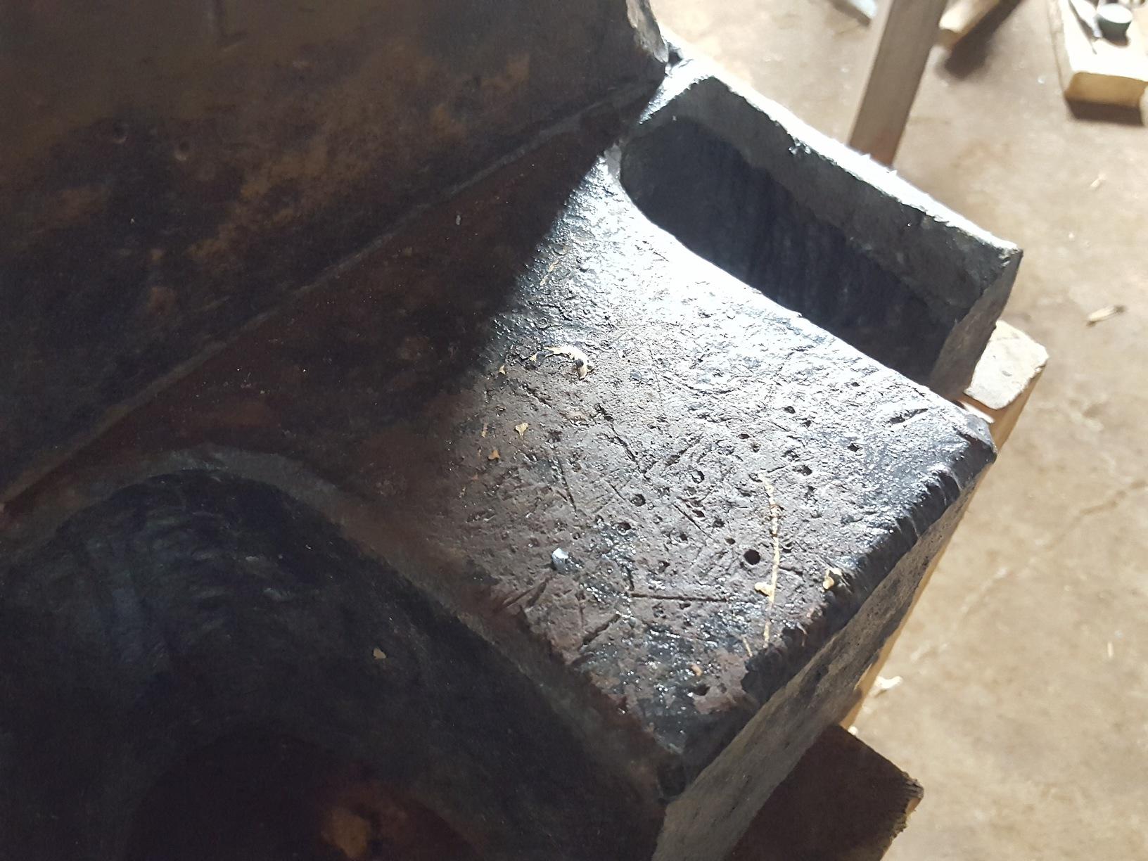
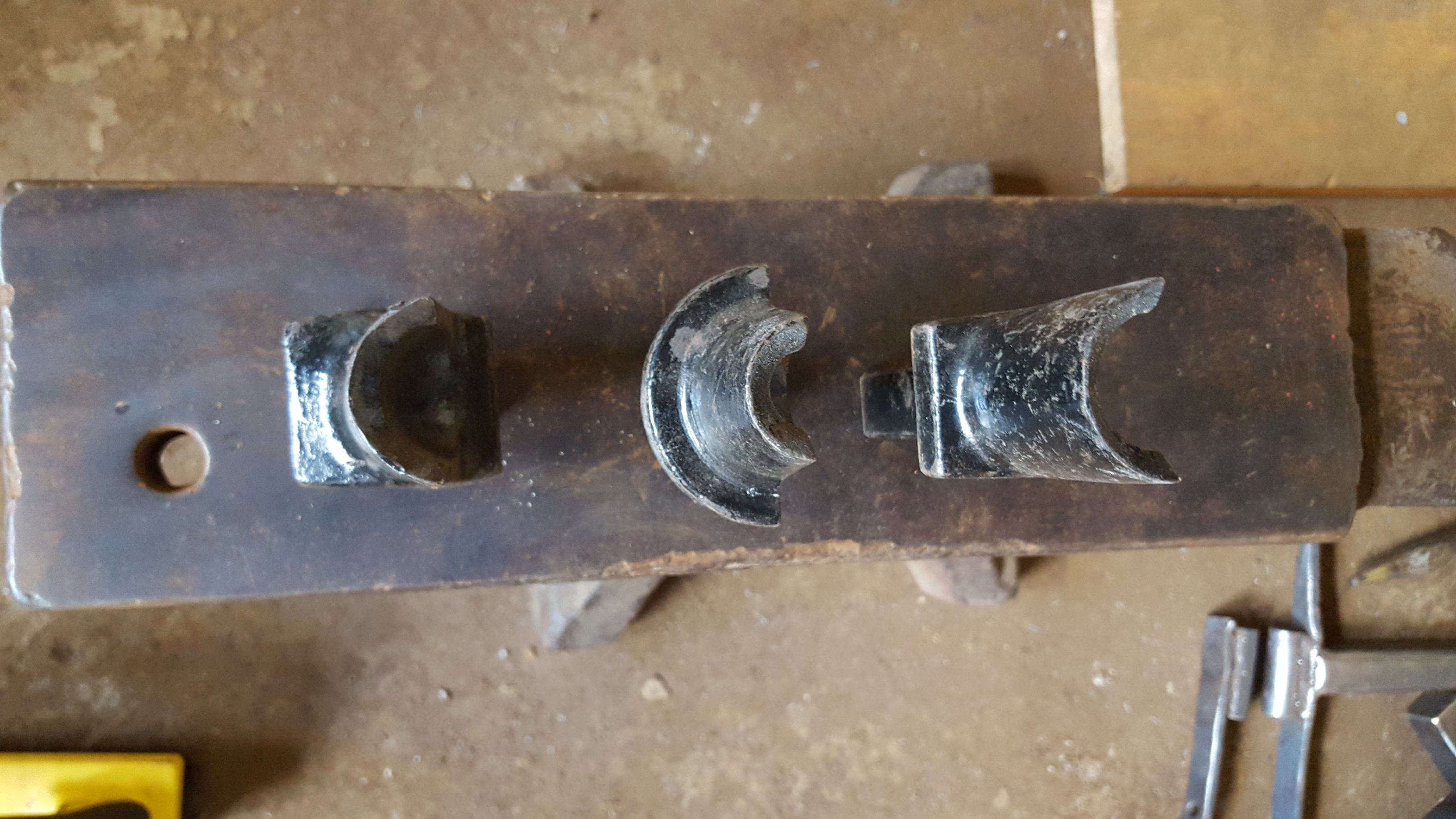
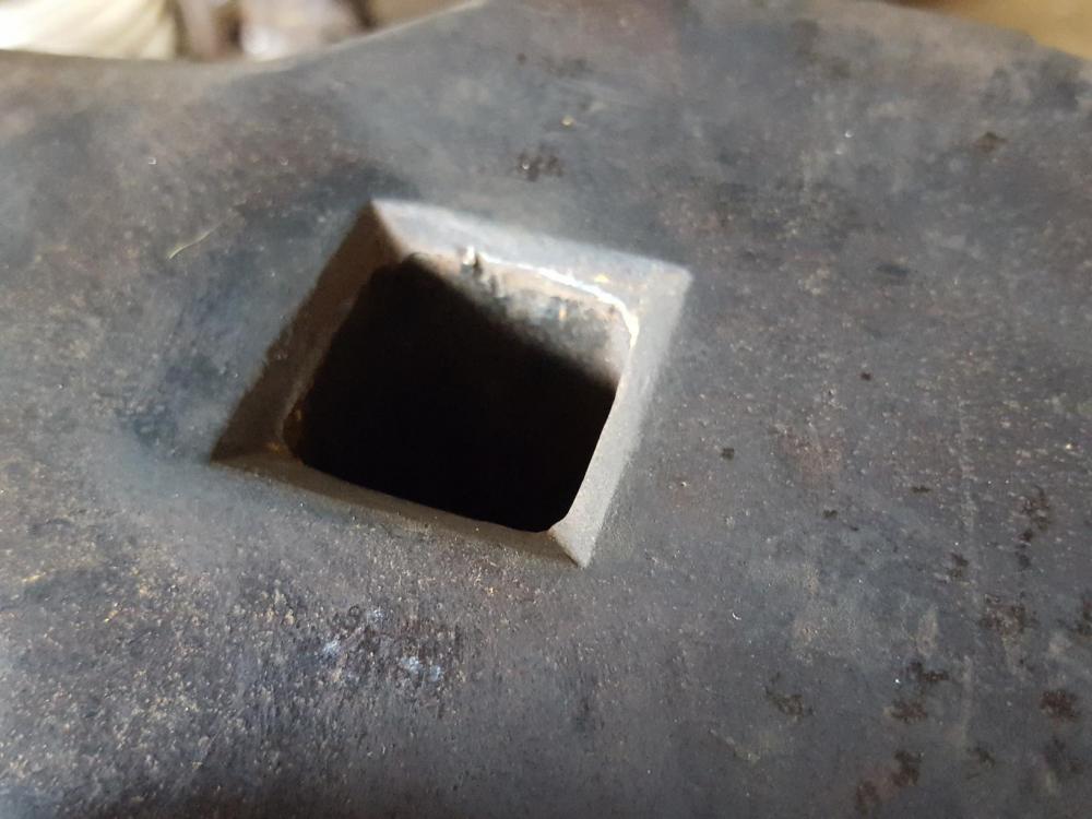
What are these for?
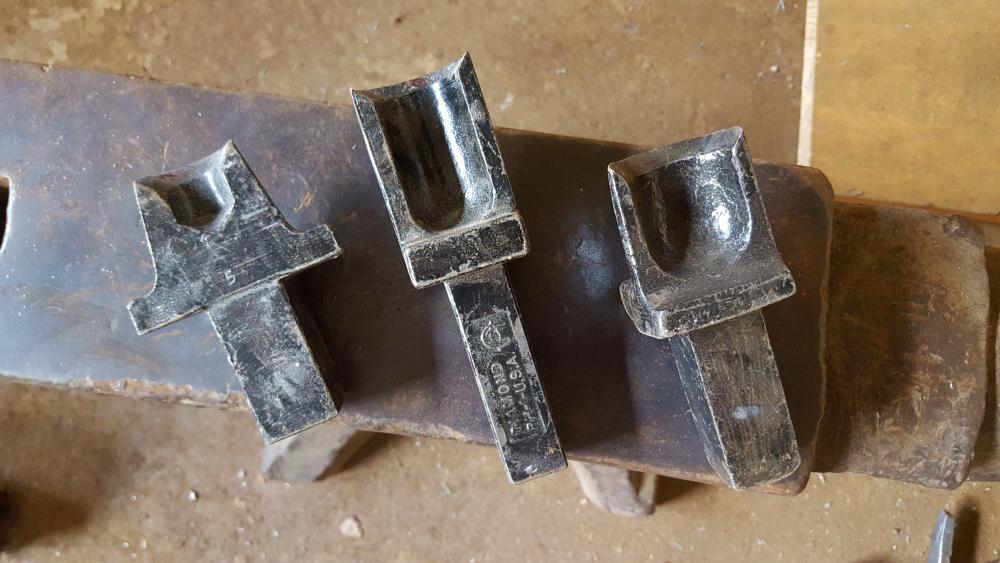
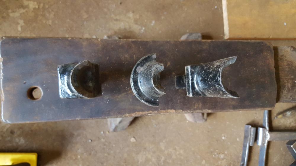
-
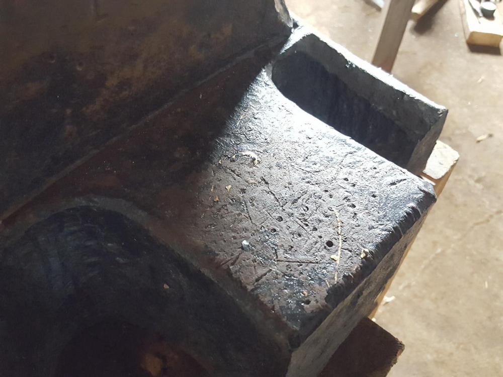
newb question: What's the purpose of forging the troughs (indentations that separate the faces from the cheeks)? Is it just to control the length of the hammer? why not leave them out? Tyler