

Gayle Brooks
-
Posts
323 -
Joined
Content Type
Profiles
Forums
Articles
Gallery
Downloads
Events
Posts posted by Gayle Brooks
-
-
Here is a shot of the press tool I was using to create the button, its a one heat squishing.

Typically when I start assembly they are off a little. As much as 3/8" off center of the other ring.
I clamp it down and use a bending fork to grab it. It will bend at the weakest point which is at that shoulder.
The riveting tool I use is a punch. Im able to reach down there, have my hands clear and hit the rivet exactly where I want.

If the piece starts to get to hot to handle I use a magnet to hold my rivet while I flip it over and get it in place.
-
The topic name is the job name in the studio. We are building 2 chandeliers for this client. The one I will be sharing is the larger one. It had 3 rings to it. The largest, bottom ring is 5 feet in diameter.
Since this chandelier is a focal point, I figured it would be important where the points of focus would be. That way if I had a lamp that was not a pretty as the others, there would be a place to put it with little to no distraction. So there are 15 lamps in total. In which I numbered them and will use this reference for assembly.
Currently it is me and our apprentice making this. I was handed a sample of what the lamps on the chandelier will look like. We had the apprentice make the rings, I started on the bars with the forged tabs on the end.
These bars are 1/2" x 9 1/2" long. I was to upset each end 1/2." When we start mass producing these parts, kind of get in a production run. I used a torch and a swage block that had a 1" concave shape on it. I was aiming to get it up set and the first initial flatten in 3 heats and keep it under 5 min. I notice while I was forging these, the swage was bouncing around and alot of energy was being transferred in that motion, and not the steel. So a quick bungie to tie it down. That saved me one heat and got it down to 3 min. Minutes saved like this are great because they add up so quickly. The 3 pieces to the right of the center punch are the steps to get to the button shape.
Next was using the press, I'll get some pics of this next week. But in a nut shell I had a block setup with a 1/4" shoulder on it and squished the mass I upset to get a nice little button.
and the jig to find center for my holes. There is a hole on the back that you cant see, I used a transfer punch to index them.
and then assembly! Ill let this pic do the talkin
Thanks for reading! Ill post more soon.
-Rory -
-
man I think it would look nice! lol I'll let someone try it and see what it looks like
Hey thanks walkerironworks84 and longhunter! -
:D nice!
-
:) thanks. I forgot to show a pic of it installed. Installation went really smooth. Again I apologize for the camera phone pic. Portfolio pics should be taken with in the next ffew weeks when the house gets done.
-
very cool!
-
I recently jumped on in the middle of a project and was assigned to make the volutes for the grip rail. I took some time and thought how to make this fluid, spiral, descending shape. A thought came to make this upside down. To pull the cap like a slinky to get this shape. We have a hoist that spans most of the shop that could accomplish this.
First was to make a template of the stairs and using 3/8" round bar I bend up a template based off the layout of what should happen.

Here is the cap with the spiral already made. It is flat in this picture.
Using flat bar, I welded these additional guides onto the flat bar. They are put on with a level. I also transferred the line down to the table for reference when I start to manipulate this.
So heating it up in the forge, I clamped it down and had an eye bolt already for the hoist. I had a guide to assist when I reached my height for the center. The first pull came out very close.
Some shots of adjusting to the template

Then finally start tweaking and fit to the template.

Thanks for reading! -
Clear Lacquer (we use the Deft brand)
-
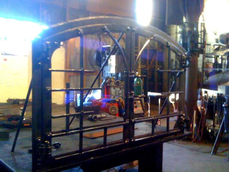
yes, all the pieces for the door frames and the frame the doors hang from were forged and welded together. And with the glass in them yeah the weigh a weeee bit!
-
The copper is a nice touch, great tip on the plunger. I'm sure they will be very pleased.
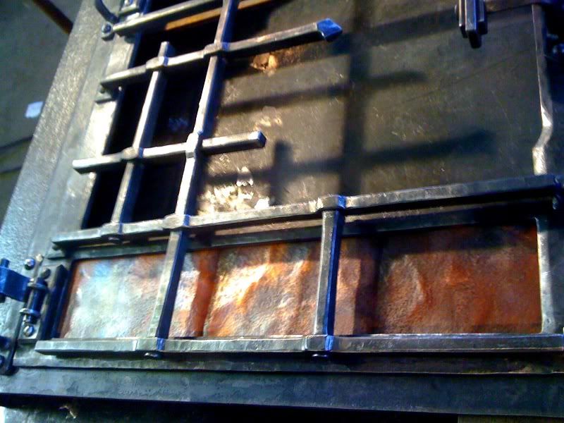
Originally they were going to go with some bronze plate on the bottom. I was concerned about weight and the doors sagging. So we met with them and showed some other sample pieces. They really turned on to the copper. Which was great since it eliminated a possible issue.may I ask how did you get the worn/scale peened type look on the large parts of the frame?
its very consistent and I like the look
It is called "boiler plate." At least that's what they call it at the scrap yard. But it comes with that texture and typically loaded with rust.I have admired your family work in the past
dad has taught you well ty
-
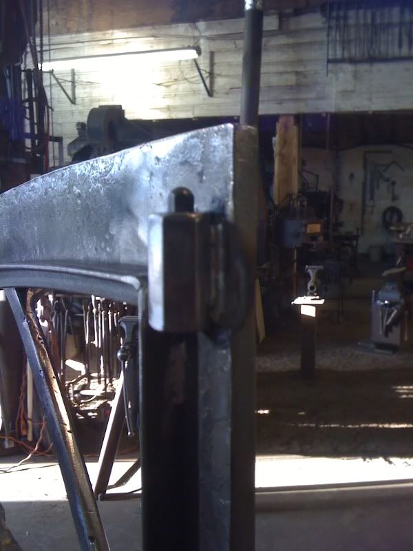
Typically when we hang fire doors, we set them up straight. Here you can see I have 3/4" round back welded to the back of the frame and the table to brace the frame. I also will weld some angle iron on the table for the base. In this case the frame was flexing a little from the weight, so I welded the corners down to the table. Before I hang the doors I make sure my frame and doors were built flat from the beginning, and hang it level in every direction. If these are not met, it makes this part of the door hard to do. I apologize for the blurry pic

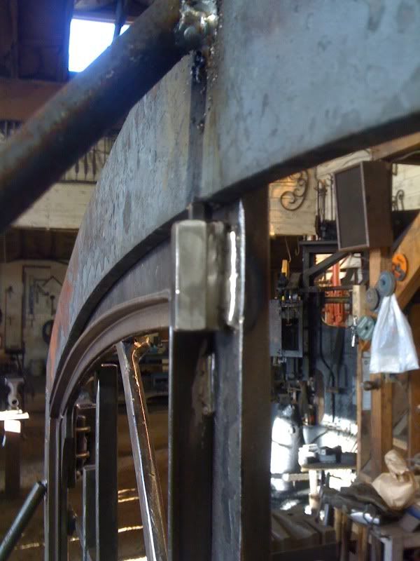
The right door went in fine, the left door I had to budge a little. One risky technique is to heat up the hinge, place a wedge (I happen to have a flat head screw driver with me) behind the door. While the arm of the hinge is hot, you place the wedge behind the door and close it forcing that side to move out. This is risky becuase the door can also move to the center of your frame giving you even more problems. I was lucky in this case since it work well.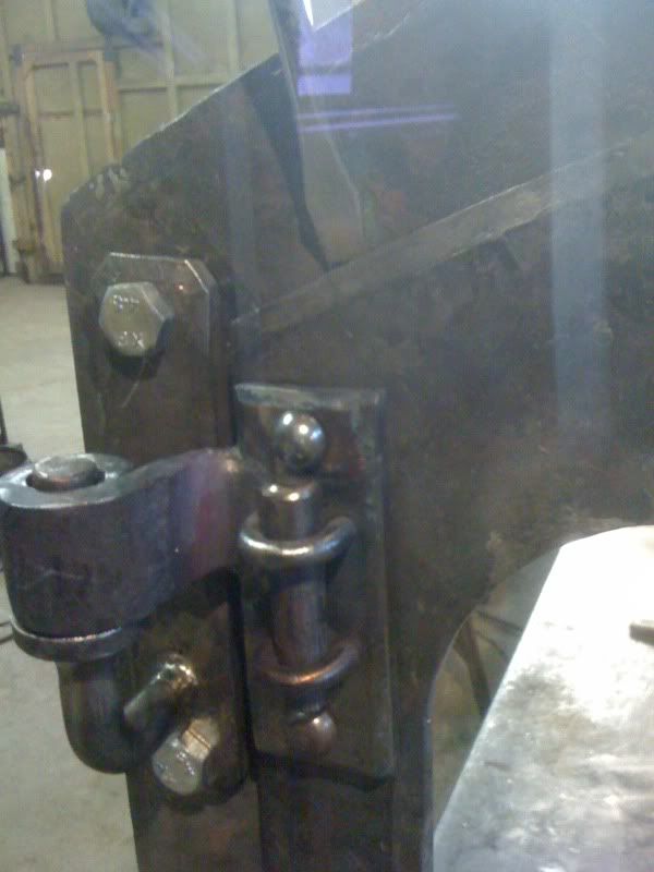
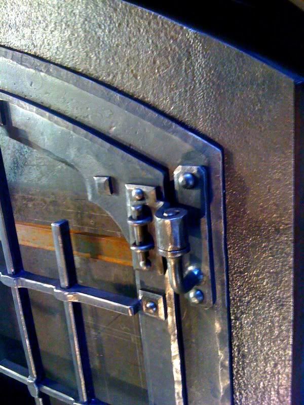
I was asked about how we keep the doors closed, if we use magnets. We used to, but it was always a gamble if the glue really took. Seemed that half the time, we would have to reset them. So we use these little plungers. They are adjustable and work great. You have to bevel a little notch on both sides of the frame so it has a ramp to ride against and snap into place.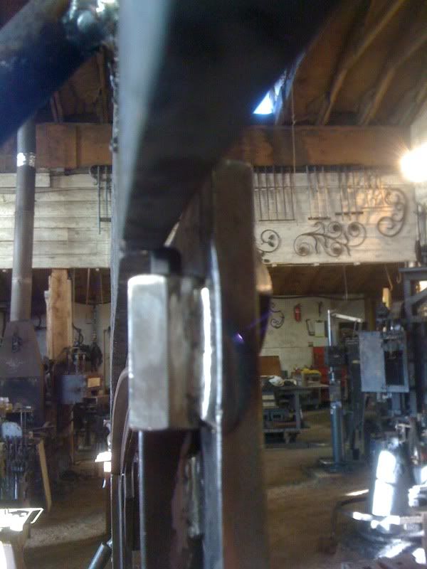
Later today I got the detailing done, copper in place and ready to paint. This will get a clear laquer and the copper will get a wax finish. Keep in mind these doors are 5 feet across.
The copper has a backing plate on it so it can be attached to the door, and is more rigid in case someone pokes it.
Thanks for reading and replying! Install this guy next week and on to the next project!
visit Dragonforgeltd.com if you would like to see more of what my dad and I do.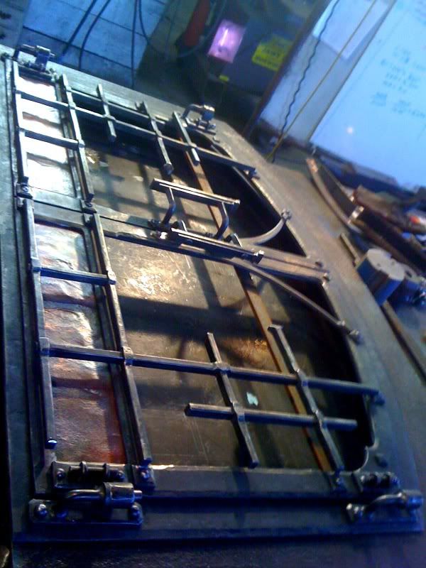
-Rory -
wow, great replies! I have forwarded this topic to him as well. If anything I learned alot more than I expected about these hammers.
Also a reminder that this is not my hammer, but a friend's at his shop.
When I hear the solution he has done Ill let you know. Thank you all again for your input, replies and insight. It is greatly appreciated!!
-Rory -
Sorry, all my experience is at sea level. Scratching my head on this one. Could be a serious issue. Is he really going to bore out the compressor cylinder and make a new piston and rings and all, just on the speculation that it might work?
Is the ram not raising? Let's hear the symptoms before we start looking for solutions. Then we'll first try the normal sea level fixes. Might just be jumping to conclusions without enough facts. You may have reached a conclusion too soon and you'll end up chasing your tail based on what could be a false premise.
From what I have heard that there is not enough air on the back stroke to return the die to its idle place.
A plate has been placed on the exhaust to help give some more back pressure. I am told that it has helped a little. And that's the theory, larger hole for the air, more air can come in.I think it is an air flow issue. At higher altitudes there is less oxygen, and the air is thinner, but a compressor would still pressurize the air going into the hammer. I may be wrong, but forcing higher cfm into the hammer should work. Just an opinion. Grant will have the answer, he always has the answer!
I agree I thought there would be a easily adjustment to compensate as our shop has adjusted with our Bull hammers that have dedicated air compressors with gauges.
I am guessing this isnt a common issue with higher altitudes being that there is no such literature online that I can find. I dont currently happen to have a manual of either the nazel or sahinler on me. -
lol thats great! love the pic
-
In Pine, Colorado our elevation is around 8600 ft. Quite high! I have a friend who lives at a similar elevation recently bought a Nazel from Mr. Bob Bergman. He recieved it, hooked it up and turned it on he found out that at our elevation these types of hammers have a hard time performing. There just is not enough air.
I personally might get a sahinler soon and am concerned about the elevation issue as well.
Has anyone else dealt, heard or resolved this issue of high elevations and self contained air hammers. Last I spoke with him, he was talking to Bob and is going to bore it out to allow more air in at once. I personally have little experience with these hammers. Is there an adjustment that can be made to assist this before actually modifying the hammer??
Thank you so much for your time!
-Rory -
Thanks Andrew

As for the handle I went here http://www.redaviscompany.com/edgedweapons.html and ordered:
22" Premium Curly Maple Handle
I also ordered a "nut brown" stain, a sealer, and a finish they use for gun stock. Makes it really smooth with each coat you add. I didn't want it to look to fake, so I added one coat.
They sell a "pipe hawk" kits with instructions, a cast head, pewter, etc. Might look into them. The booklet has some neat tricks and tips. I ordered one since I was curious about the "pipe hawk." Though I filled that pre-drilled hole with a 3/8" round bar.
Hope it helps and good luck! -
Rory,
Your works visual vocabulary is exceptional and the execution is flawless. How long you been smithing? Who does your design work and do you contribute some of your forging sensibility to your location? Pike must be a beautiful place to live and work. Have any photos of your shop setup?
Wow Michael! Thank you for such kind words. Some about me: I'm a second generation smith and am 28 yrs old. I grew up in the studio. It was used as punishment for quite some time when I was younger. I never really got grounded, I just went to work with dad. I have been full-time since I was 15. I work with my father and 99.9% of what I know, and how to do it, is because of him. I take an occasional class but most of the time he is my walking library. I could not do this craft without him.
As for the business side of things, I get handed a design that he has drawn up. I am allowed the freedom to interpret the drawing how ever I see fit --as long as it looks like the drawing at the end-- and I finish with in the given amount of time to stay with in budget. Most of our work has been in higher end custom homes. The designs are custom to each client. Either based on their personal experience and/or design of the house. As for these firedoors he is really liking them. Has made the comment "I like where you have taken these. Nice touch."
The shop is quite large. It has been 30 years of my dad gathering, building, modifying. The past 10 years of my contributions as well.
Some update pics of what I was able to get done today.
Rolled some barrels and fabed the pins into place.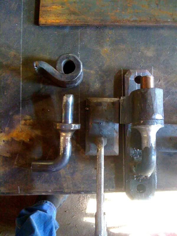
Riveted the grill and handles
-
Thanks!
The mounting pads for the handles were welded on. -
found some in progress pics wewt!


and a close up on the head -
thanks for the kind words, Beth
update on these doors. Got the grills done. I have left is to hang them, rivet then grills on, build the glass frames and some fine details.
Handles riveted together. A tenon was forged on the end of the 1/2" square stock and riveted through the 3 pieces of flat bar
-
I gave the topic the same project name that it is in the studio.
After cleaning up the working drawing I was given, and got the small details figured out I went to the prototypes for the grill of these fire doors.
This particular one was a type of "knuckle" joint. The challenge was to forge this detail and be able to do it so that another joint could be laid out on the same bar. I tried to forge this out on the anvil and power hammer, though could not get a consistent, controlled result. So after upsetting the mass, offsetting it to one side, drilling a hole and cutting mass out to create a slot; I used a press to squish this joint out. I made some tooling for the press that had 2 shoulders to control the piece to stay inline. Ended up breaking the press step up in 2 parts. One was using a 3/8"x 1" flat bar and set it in the joint under the press. Next I opened it up a little making room for my 1/2" x 1" bar and doing that last squeeze. The result was nice and very clean.
I apologize ahead for this is a camera phone pics.

Thanks for reading! Ill post more soon. -
upset, 2 sided taper leaves? Typically I get those long one when I fuller off to much mass.
can only guess that kind you are making. hope it help! -
very cool! gj
Hearts for Valentine's Day
in Blacksmithing, General Discussion
Posted
Good stuff!
Here Is mine