February 3, 201610 yr my idea is to run a 5/2 solenode like this http://www.ebay.com/itm/1-2-DC-12V-5-way-2-position-Pneumatic-Electric-Solenoid-Valve-NPT-Air-Aluminum-/281360345142?hash=item4182622836:g:Mp4AAOSwhh5Tmlqn then wire it to a flasher unit like this http://www.ebay.com/itm/2-Prong-Electronic-LED-Compatible-EF32SS-Solid-State-Turn-Signal-Flasher-25-Amp-/400665610452?hash=item5d498808d4:g:SuUAAOSw~gRV6Kss&vxp=mtr with a ball valve on the exhasut port linked to a foot peddle will it work is what i am wondering i know i cand do the electric all easy but not sure if an electric controlled 5 way will fill and empty fast enough to hammer with
February 4, 201610 yr Author ok s 52 views and no answers then let me pose another question the spring on a kinyon style has any one used sway bar s from a rease set up was thinking put the narrow end over the hammer side so that as it piviots that side will get mor whip out of it but with a shorter depth over all a world wide forum and you have decided 11 hours is too long to wait ? hmmmmm.
February 4, 201610 yr You need a 2 pilot shuttle either air or electric and a limit switch at the apex and another at the lower stop. However there are still problems to overcome like supplying power, mechanical cycle limits etc. You could use the existing single dc pilot shuttle you pointed out and using a contactor and auxiliary keep the pilot active until it hits the stop and turns off to reverse the shuttle. As for your sway bar question.. Probably not as they're typically rigid as the application is to stop sway. Why reinvent the wheel if you don't have to? J
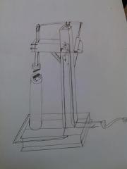
February 4, 201610 yr Author i drew up a quick scetch of my idea with the weight distributing bars in the middle of the second pic only reson ask about them is i have 5 sets sitting in my shed right now i am looking at about 60 pounds for the top die and verticle bar my under standing on the 5/2 solinode is that when paower is supplied one port is charged with air and the other is oped to exhaust when power is taken away they swap places so by alternating with a flasher it will open and close with out the extra switches and links rune ehaust thru a ball valve linked to foot peddle
February 4, 201610 yr And you're going to have no control of the tup cycle. There's a reason limit switches are used versus timed circuits. This isn't a static machine with cyclic rotation, it's dynamic as is the nature of the work piece under it and therefore needs to be controllable. J
February 4, 201610 yr Author ok i get ya so a air controllered 5/2 then a 3 way tied to on offs at top and bottom of ram throw but i am con fused as to what controls the bpm on an air system only .control do you ball valve the exhaust at the 3 way or at the 5 way valve i have looked thruh 6 pages of threads used the search funtion , google and youtube no budy does a complete walk thru of like air in here to this valve this vallve connect this port to this port on this valve back to these swithces . there is a pnumatic can crusher that is automatic that that looks like it could be scaled up and ad control on the exhaust side on you tube but even he doesn't explain the skematic and most of the parts numbers people are listing as what they used when i search them come up with bubkis worst part is they say i used this valve a xxx890239029 what ever instead of i used a 5/3 piloted sorry for the rant i have been tring to design this thing for a while now and am down to the controls i dont like spending money in the blind i have managed to source every thing but the cyclinder and controls . i am slowly going insane on this one. ps thanks for the help JWS
February 4, 201610 yr Only two ports on the limit switch are needed. Mainline air supply (P) branched from the same that supplies your shuttle and the exhaust port (A) which will go into your pilot port. Exhaust is all handled on the shuttle and by using a ball valve the flow rate can be changed which controls the speed of the cylinder. On the design you drew a single pilot/limit switch would work. It would go on the up stroke to switch the shuttle and allow it to drop the tup. J Here's an example of the switches I use.
February 6, 201610 yr Author thank you i was able to actual search for that one you wouldnt happen to haqve a pic of the rest of you controls
February 6, 201610 yr I can't comment on the electrics, but I think there's a basic mechanical problem in your sketch. Your spring, or swaybar is drawn horizontally, and as the hammer raises, the distance from the center pivot point to the slide changes, and I don't see a way to compensate in the drawing. I think a shackle on the front would not transfer power very well.
February 22, 201610 yr I am building a hammer and had similar thoughts (because somebody basically gave me a spring return solenoid 5-way 2 position valve). The only way I could think to run it was to put an electrical switch half-way across the travel and have it act like a normal Kinyon, or put one switch on either end of the tup travel and use what's called a 'latching relay' which holds the relay in position one until the other switch is triggered, then holds in position two... then back to one, and so on. I'm still only getting close to finishing my hammer, so I'm no expert, but I figured it might have made sense. I have since switched to a dual air pilot valve because I wasn't sure I wanted the hassle of plugging it in and troubleshooting two systems (and I think the solenoid valve was siezed - thanks buddy!).
March 4, 201610 yr Here's what I learned (including my schematics): http://straightrazorplace.com/forge/122144-air-hammer-4.html
Join the conversation
You can post now and register later. If you have an account, sign in now to post with your account.