mofokaye Posted May 14, 2012 Share Posted May 14, 2012 Following my previous attempt at building a helve hammer, shown here: ...I decided to stop buggering about, and do it properly. Here is my progress so far: The basic metal frame, and the hand forged crank shaft in what will roughly be it's eventual location. Shown in this picture is the dies, made from rail track, which will be held in 'rail chairs'. The crank shaft, finished on the lathe and polished. My job for later in the week will be making the bearings and mounting them in place. The monstrous 8-belt drive pulley. Wouldn't want this falling on my foot. Everything clamped roughly in place to give an idea of the final dimensions. Hopefully I'll be obtaining a solid lump of 16" square 12" thick plate, hacked from an old car crusher to use as the anvil mass. And the obligatory shot of my tiny messy workshop. Hopefully many more progress updates over the coming weeks and months! Quote Link to comment Share on other sites More sharing options...
mudbugone Posted May 14, 2012 Share Posted May 14, 2012 Good Luck on the project. Looks seriously heavier than your first hammer. Those rail chairs are interesting haven't seen those before. That looks like trolly rail instead of standard rail material,but it looks like it'll be great for your intended usage. I found a bunch of it several years ago and like an idiot didn't grab a couple of sticks,but at the time I was purchasing other material for different projects..Can't hoard everything I guess..LOL Thanks for sharing your project ...that crankshaft looks interesting. I need to make something similar,but I'm going to try to make it so it can be disassembled by fabricating it out of pieces instead of a solid crank. Quote Link to comment Share on other sites More sharing options...
mofokaye Posted May 14, 2012 Author Share Posted May 14, 2012 Those rail chairs are interesting haven't seen those before. That looks like trolly rail instead of standard rail material,but it looks like it'll be great for your intended usage. This is a very common form of rail over here in the UK, and for the largest part of our rail networks history, these cast iron rail chairs were the standard method of attaching the rails to the sleepers.... Subsequently, if you know where to look, there's millions of them! As for my intended use for them, it's a complete shot in the dark... But if it works it'll be a very quick way for me to swap dies. I made a solid forged crank simply due to the stresses I expect it to encounter, but one I could dismantle would make life a lot easier. Good luck! Quote Link to comment Share on other sites More sharing options...
mudbugone Posted May 14, 2012 Share Posted May 14, 2012 That explains it...over here they use plates and wider bases on the larger rails to do the same thing. From what I've seen an eccentric is usually used on a straight shaft,but there is a lot of machining involved to replicate that design. I found the following design that's for a small scale model,but if sized larger should be workable for such a machine application with some modifications Quote Link to comment Share on other sites More sharing options...
mofokaye Posted May 28, 2012 Author Share Posted May 28, 2012 So, a few weeks later and the bearings are complete, with their own grease cups salvaged of some decaying quarrying equipment. The flywheel is now attached (Although slightly off balance, which is something I'll address next time I have a free moment) And the motor is bolted solidly into place. Much more to be done, but a brief test of the crank assembly can be seen here: Quote Link to comment Share on other sites More sharing options...
Jim Kehler Posted May 28, 2012 Share Posted May 28, 2012 I like it! :) What are you using for a clutch? Quote Link to comment Share on other sites More sharing options...
mofokaye Posted May 28, 2012 Author Share Posted May 28, 2012 It'll be the classic slack belt clutch, the belts are just tightened at the moment so I could test the bearings, etc. The whole foot pedal assembly is next on my list of jobs :) Quote Link to comment Share on other sites More sharing options...
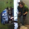
mofokaye Posted September 4, 2013 Author Share Posted September 4, 2013 So, it's been over a year since I made any real progress on this thing due to a heavy workload, other life commitments, and spending 2 months in a darkened room with bleeding eyeballs. Y'know, usual. But, I'm back on it now, and determined to have this thing up and running shortly. So, this weeks progress: The anvil's done. Made out of some heavy channel, and lots of scrap round bar welded into it, it forms a formidable lump. No idea how effective it'll be, but it's the best I can manage at this time. Also you can see my use of these British rail chairs I mentioned earlier in the build, both bolted firmly in place, holding the rail track dies. And another shot of the front of the hammer Next I attached the helve to the frame, and installed the grease cups on the brass bearings Now to work on actually transmitting power to the helve. I'm looking at using a Bradley style rubber cushion design, but will be running some small scale experiments first. Lastly a look at the thing so far, apologies for the typical horrendous state of my tiny workshop. Quote Link to comment Share on other sites More sharing options...
mudbugone Posted September 4, 2013 Share Posted September 4, 2013 I really like those rail chairs... They add not only weight to the structure ,but looks like pretty stable attachment of the rail dies too. They give the hammer a vintage look instead of totally fabricated..as if they were ment for the purpose you're using them for..I've never seen anything similar around this area ---Unfortunately--- or I'd have to copy that design.. (what's S&H from the UK ? LOL ) just seems to fit a helve hammer.. What do they weigh ? also ... what will the hammer head weigh(the rail & the rail chair)?Sorry you've been down & hope you're feeling better. Quote Link to comment Share on other sites More sharing options...
Everything Mac Posted September 4, 2013 Share Posted September 4, 2013 I like it. Are you able to put a video on YouTube when it's finished? Andy Quote Link to comment Share on other sites More sharing options...
mudbugone Posted September 5, 2013 Share Posted September 5, 2013 I keep looking those rail chairs over trying to figure out how the rail is held in place ,but I don't see any bolts to clamp the rail ???? Surely the chairs aren't slipped over the rails and then bolted down ? Just curious & intrigued by their design.They really do fit that hammer well. Quote Link to comment Share on other sites More sharing options...
mofokaye Posted September 5, 2013 Author Share Posted September 5, 2013 The way the rail's held in place is quite clever, but possibly no good for my uses... So some future improvisation may be in order. I'll try and show as best I can, and failing this get some decent photos tomorrow. Here's the best picture I have: There's a U shaped spring that is hammered in behind the rail. This holds the rail in place whilst giving it a slight amount of movement to accommodate passing trains. For my purposes though I fear the rail may just bounce loose after a short period, but I'm sure I can come with something. As you appreciate, these rail chairs are just too good to pass up. I'll see how successful they are, and if all goes well maybe we can discuss me shipping you over some ;) As for a video, fear not, there shall definitely be one up once it's up and running! I believe there's already a link to a video from last year of just the crank running further up the thread :) Quote Link to comment Share on other sites More sharing options...
mudbugone Posted September 6, 2013 Share Posted September 6, 2013 Ahhhhh ! That explains a lot..Thanks.You may be alright with those spring clips..(you could add some sort of retainers if it becomes a problem)..rails usually are exposed to a lot of movement (maybe even more than you'll have for the hammer) rail cars shift & move a LOT while in motion.If they function as you hope...You may have requests for dies & mounts from others as well...LOL. You're rails are designed different than ours are. Those almost look as if they could be turned over and used upside down.Careful you might have a side business ???? to pay for other toys.. Can't wait to see this in operation. Quote Link to comment Share on other sites More sharing options...
mofokaye Posted September 6, 2013 Author Share Posted September 6, 2013 Mainline trains no longer use this system, and have a more typical flat bottomed rail held to the sleeper with spring pins like this '> However thanks to Dr. Beechings railway cuts in the 60's there are literally thousands of miles of abandoned railways in the UK... and subsequently MILLIONS of these rail chairs laying about. There may well be a profitable business here :D Quote Link to comment Share on other sites More sharing options...
LastRonin Posted September 7, 2013 Share Posted September 7, 2013 Mainline trains no longer use this system, and have a more typical flat bottomed rail held to the sleeper with spring pins like this '>However thanks to Dr. Beechings railway cuts in the 60's there are literally thousands of miles of abandoned railways in the UK... and subsequently MILLIONS of these rail chairs laying about. There may well be a profitable business here :DHopefully your government is not as stern and strict about people messing with 'abandoned' rails as ours is. The hammer looks interesting and promising.I do have a question though... just guesstimating from the pictures, but it looks to me like your cam has about 4" of movement? is that all the movement the heads will have, or will it be adjustable, possibly by having options for how far out along the arm you attach the pushrod...? Quote Link to comment Share on other sites More sharing options...
mofokaye Posted September 7, 2013 Author Share Posted September 7, 2013 Hopefully your government is not as stern and strict about people messing with 'abandoned' rails as ours is. The hammer looks interesting and promising. I do have a question though... just guesstimating from the pictures, but it looks to me like your cam has about 4" of movement? is that all the movement the heads will have, or will it be adjustable, possibly by having options for how far out along the arm you attach the pushrod...? These rails have trees growing through them, believe me, the government aren't worried. :D Once done it should have10ish inches of movement, and it'll also be height adjustable for working on larger stock. This is the plan anyway... Quote Link to comment Share on other sites More sharing options...
mudbugone Posted September 7, 2013 Share Posted September 7, 2013 The few inches of movement at the eccentric translates to quite a bit more movement at the hammer head.Should be interesting to see how you build in adjustability for thickness.... Some sort of turnbuckle arrangement in the connecting rod ?I've been designing a similar type hammer & taking design clues from several antique hammer patents. The Bicknell's power hammer(first design 1903)while not having a patent number (picture only) shows a dual single leaf spring (top & bottom of helve)which looked compact & simple enough to replicate using common small trailer springs instead. After I sketched up drawings ( and still researching ) I found I was not the first to imagine such an assembly. although I think the Bicknell hammer inspired that configuration as well.The Hathorn helve hammer design is one example of a similar type hammer that incorporated not only an adjustable height feature ,but a slide arrangement to adjust the hammer impact as well...patent number 758,361 in 1904. It originally featured a slotted attachment thru the beam which was obviously later changed to a slider located on top of the beam. This was done probably for simplicity of construction or strength of the beam structure or both. This is shown in later Hathorn hammers as well as the Rochester Helve Hammer (a later configuration of the Hathorn design)The later slider design consists of two plates on top of the beam which allow the U-shaped leaf spring strap to be slid front to back causing the helve to hit harder or softer. In order to utilize a double leaf spring design (like the junkyard hammer) & retain that adjustability some sort of roller assemble would have to be designed that would allow the entire spring assembly to be slid forward & back (rollers?) but still maintain rigidity as well as some way to lock things in place much like the Hathorn latch assembly.I'm amazed at the way the old hammers were designed from scratch..at least we have the options of their design imagination and knowledge to draw from as well as modern bits & pieces to speed the process along..... and they designed & built & sold them for around a $100...How cool is that.Thanks for sharing you're efforts with all of us.. I'm enjoying your labors and learning as well. Quote Link to comment Share on other sites More sharing options...
mofokaye Posted September 7, 2013 Author Share Posted September 7, 2013 It's an education for me building this thing! I've opted against the use of springs, as I had an old leaf spring from a truck go in my face once. Not pleasant at all. Instead I'm going for a Bradley style rubber cushion system. Or atleast, I'm going to try it before submitting to steel springs. As for adjustment, it'll be as simple and removing a pin, and moving it up and down a few notches accordingly. As for adjusting hammer impact, I'm confident enough hat the clutch will provide all the control I'll need. That said, this entire project is a shot in the dark, and my ideas may change as the project progresses. Quote Link to comment Share on other sites More sharing options...
mudbugone Posted September 7, 2013 Share Posted September 7, 2013 I considered the rubber cushion route and if I ever run across something like large axle snubbers from some big vehicle I'd be open to such a design. If I'd ever had a leaf spring explode in my face I'd understand your feelings...as it is I may add some sort of spring wrap if I get the feeling there is too much tension being placed on such a spring configuration while in operation. I don't think the stresses on a double spring arrangement like this will be as great as those on a single leaf spring arrangement where the spring is actually a major part of the working assembly.Usually we work around what we have available to make things work. I "have" several sets of small leaf springs from old golf carts...LOLI will mention that the Bicknell hammer evolved into using rubber snubbers in later configurations (1904). The upper & lower single springs became more rigid arms and the rubber snubbers controlled rebound while the spring arms became more a part of the frame much like the larger Bradley hammer designs. I finally found a photo of that later configuration (the earlier design is far different)... http://www.vintagemachinery.org/mfgindex/imagedetail.aspx?id=7003You're doing just fine as you are. There are many variables when building from scratch and unless it doesn't work it's just fine.You may find a source for large rubber snubbers in some automotive application. Quote Link to comment Share on other sites More sharing options...
mudbugone Posted September 10, 2013 Share Posted September 10, 2013 I got to searching for some sort of rubber bumpers that might be usable for a scaled down helve hammer much like the rubber bumpers used on a Bradley. I was surprised that finding something was easier than I thought. I found examples of truck loading dock bumpers Axle bumpers Even some Volvo springs with interesting rubber bumper inserts http://www.ebay.com/itm/98-00-Volvo-S70-set-of-left-and-right-rear-coil-springs-bump-stops-isolators-/360721958014?pt=Motors_Car_Truck_Parts_Accessories&fits=Make%3AVolvo&hash=item53fcb4447e&vxp=mtr Jeep Wranglers had nice square rubber bumperettes too. It would just be a matter of checking many sources to determine if they had rebound enough to stand up to something like the constant hammering they would face. I thought the used Volvo snubbers would definitely hold up (but might be too long) The truck loading dock bumpers (the rubber ones not the tire ones) are probably durable also. Thanks for getting me to thinking outside the box and looking into the options. There may be even more ....Morris Minors use a cone shaped axle bumper,but I couldn't tell it's size. Good Luck in finding something I just thought I'd share what I found in case you hadn't found anything yet. Quote Link to comment Share on other sites More sharing options...
mofokaye Posted September 11, 2013 Author Share Posted September 11, 2013 Fantastic stuff, thankyou! The Morris Minor axle bumpers could be good, there's quite a few rotting away round my way. Progress continues tomorrow, shall be making the bearing for the eccentric shaft Quote Link to comment Share on other sites More sharing options...
mudbugone Posted September 12, 2013 Share Posted September 12, 2013 I kept looking & thinking--- http://www.socalautoparts.com/index.php/sway-bars-amp-bushings-c-1261_0_1314_1501 I really miss the old VW's cheap to operate & even cheaper to fix... That assortment of axle bumpers might be what you're looking for. The fancy ones that come as a pair are bright... LOL Many trucks use rectangular axle bumpers which have two bolt mountings which you might check into also. Quote Link to comment Share on other sites More sharing options...
mofokaye Posted September 12, 2013 Author Share Posted September 12, 2013 I like the bright red ones, very fancy haha :D I shall give that a look, thankyou! Quote Link to comment Share on other sites More sharing options...
mofokaye Posted September 16, 2013 Author Share Posted September 16, 2013 Made some progress again today. Got the eccentric bearing done: And the arms that'll transfer the motion up to the cushion/spring linkage: At this rate I should be taking this thing for a test ride soon! Quote Link to comment Share on other sites More sharing options...
mudbugone Posted September 16, 2013 Share Posted September 16, 2013 Nice pictures... Good Luck... Quote Link to comment Share on other sites More sharing options...
Recommended Posts
Join the conversation
You can post now and register later. If you have an account, sign in now to post with your account.