

timgunn1962
-
Posts
393 -
Joined
-
Last visited
Content Type
Profiles
Forums
Articles
Gallery
Downloads
Events
Posts posted by timgunn1962
-
-
The soluble stuff is more usually termed body-soluble or bio-soluble. I don't think it's intended to be water-soluble per se, but it will supposedly dissolve (quite slowly) in body tissue and should therefore present less of a long-term risk to health than insoluble fibers. I assume it'll be a few decades before there is hard information on the relative long-term health effects of both types. In the meantime, industry seems to be following a precautionary principle and going bio-soluble where practicable.
I think the body-soluble stuff had a maximum temperature rating around 2300 degF last time I looked into it, which left the insoluble stuff as the material of choice for welding temperatures. It was a few years ago and things may have moved on since.
-
It's certainly worth doing some serious research. Mostly you'll see electroplating kits, but it might also be worth looking into electroless Nickel if you are intending to plate uneven surfaces.
-
From your description, it's sounding to me like you want a pretty normal forge with both ends open, but with a tubular heat-shield arrangement on the back end to eliminate fire risk, and even heating over the full 24" is not required?
If that is indeed the case, I'd build a 24" deep forge with a closed back, stick a single burner about 6" in from the front end, and treat it as a 12" long open-ended forge from the design point of view. I'd certainly expect a 3/4" burner to cope with it, though I have yet to try a T-burner.
Assuming you use Kaowool (I would), you'll want 2" of it on the closed end and you'll want to ensure there are overlaps so there is no direct heat path through the joins. From experience, I'd suggest that unless you have arms like a gibbon, it's probably easier to do this from the outside and MIG weld the end on once you've got it right.
-
What do you want to do in the forge that needs 24" of length?
I ask the question because it makes a big difference to the amount of heat input required.
If your requirement is to get 24" of Wrought Iron to welding temperature, your burner needs will be completely different to those for getting 24" of Carbon steel to Austenitizing temperature, for example.
-
It's worth checking your NG supply pressure at an early stage, as it may impact your choice of blower. It varies by location, but here in England domestic gas is supplied at 8" WC, about 0.3 PSI.
There is not much point having a blower that gives more pressure than the gas supply because the gas will stop flowing altogether when the mixing chamber pressure reaches the supply pressure.
-
For Natural Gas, you are unlikely to have the pressure available to use a Naturally Aspirated burner to any of the usual designs. There are commercial burners out there that should work, but they will be expensive and considerably bigger than high-pressure Propane burners of similar output.
That pretty much restricts you to a blown burner.
-
If you have any welding rod or similar straight wire, you can cut it with centre-cut wire cutters so that it has a vaguely chisel-like end, chuck it in a drill and drill through the IFB with it. You then snip it off flush at both ends and leave it in as pins.
When I first tried it, I ground the last 1/4" or so down to make a D-bit and it worked great. Later I got lazy and just used the wire cutters, finding the result was the same.
It only works on IFB, where there are enough voids to take the dust formed without jamming up.
-
One thing I'd look to change fairly soon is the lighting.
IP65 outdoor fluorescent lights are not expensive and the polycarbonate diffusers offer quite a lot of protection against the sort of knocks they'll inevitably get in a typical workshop. Anyone who's clobbered the tubes and found themselves suddenly in darkness in a shower of glass fragments and white powder will not want to repeat the experience.
Sealing the floor is certainly worth doing, and doing right first time, before it gets anything oily on it. I wish I'd had enough time to do mine before filling it with stuff. Whether you seal it with something coloured is up to you.
Looks like it has plenty of potential.
-
1 hour ago, Mikey98118 said:
Monkey Forge,
I advise you to disassemble the burner and internally bevel every threaded edge, which faces toward the incoming gas and air; otherwise you will have three obstructive shoulders interfering with laminar flow.
I'd just amend this slightly to "if you have significant Dragons Breath" internally bevel etc..
Doing the bevelling thing will probably increase the amount of air drawn in for a given gas flow, leaning off the mixture somewhat.
The probability is very high that you have a rich mixture and increasing the air intake will make it less rich and thereby increase the flame temperature.
In the unlikely event you have a slightly lean mixture, increasing the airflow would reduce the flame temperature.
If you have DB, you have a rich mixture.
-
57 minutes ago, Mikey98118 said:
Monkey Forge,
I advise you to disassemble the burner and internally bevel every threaded edge, which faces toward the incoming gas and air; otherwise you will have three obstructive shoulders interfering with laminar flow.
I'd just amend this slightly to "if you have significant Dragons Breath"
-
I'd recommend the one that goes down to zero pressure every time.
I tend to use 0-60 PSI regulators with my burners (use whatever maximum pressure rating is appropriate for yours), but recently bought an 8-60 PSI regulator by mistake. It is horrible: considerably more faffing about when starting and stopping.
It's much easier to get a gentle start by opening the cylinder valve and then gently increasing the pressure from zero on the reg, rather than opening the cylinder valve and getting around 1/3rd of the full-pressure output.
Gas flow varies as the square root of the pressure. 3 PSI is 1/10th of 30 PSI, so flow at 3PSI is 31.6% of the 30PSI flow: "about" one third.
Flow at 8 PSI is 36.5% of the 60 PSI flow: also "about" one third.
-
Some forges have a small hotspot. Others maintain a pretty even temperature throughout their interior. If your forge is of the latter type, location makes relatively little difference and you can put the thermocouple almost anywhere in the chamber and get useful readings.
If your forge only has a small hotspot, you are better off keeping it clear for the workpiece. Location makes a big difference and putting the thermocouple anywhere else will not tell you the hotspot temperature. In this case, you are probably better off without a permanent thermocouple.
Run your forge first. Look for color changes throughout the forge, perhaps using a thin rod to give an idea of how the color/temperature varies at different locations (it may be worth using a hand-held thermocouple to take actual measurements). You can then decide whether or not there is somewhere suitable to permanently install a thermocouple in your forge.
I tend to find the most satisfactory solution is to use a handheld thermocouple to adjust the forge to where it needs to be, then take it out and get on with the job. I only do that due to inexperience and colorblindness. Most normal folk set the burner so it looks about right and just get on with it.
The only time I leave the thermocouple in the forge is when heat-treating and that is done in a dedicated forge built specifically to provide a very even temperature.
-
It's a while since I played with a 2BF. On mine, I used a similar torch to yours, but made the hole where it feeds into the forge tapered: bigger on the outside, smaller on the inside.
This allowed me to move the torch in and out, varying the amount of air drawn in along with the main flame.
The flame from the mouth of the forge suggests that you are not getting enough air in to completely burn the gas, so there is probably something to be gained by increasing the airflow.
I agree with Charlotte that you'd be better off with a higher-output torch though.
-
The 128 kg/m3 is the better choice. It's 8 lb/cu ft in old money.
The 96 kg/m3 is 6 lb/cu ft.
There is also a 160 kg/m3 (10 lb/cu ft) blanket available in the 1425 degC / 2600 degF grade, which might be worth paying a bit extra for if you can find it.
The higher density stuff is actually the better insulator, according to the spec sheets.
-
I'm guessing you are using the .045" MIG tips for jets and have a lot of Dragons Breath?
If so, try the .035 MIG tips instead (the Zoeller page gives both sizes as suitable). While you are buying tips, it might even be worth picking up a couple of .030 tips in case you've still got lots of DB with the .035s.
The .045s should be "better" for HT: less sensitive to small adjustments of the choke and therefore easier to set a precise temperature with, but I don't think they are likely to go lean enough to get the flame temperature up to welding levels.
-
3 hours ago, Light Hammer said:
I've since added a choke to the intake though I'm not exactly sure how/when to use it. The flame will sustain up to around 20 psi then blows out. It starts "huffing" around 3-4 psi.
Try the burner in the forge, either without the choke fitted or with the choke fully open. Give it the beans and see whether or not it gets hot enough to do the hottest thing you will ever want to do with it. At the same time, check whether or not there is visible Dragons Breath (it really helps to do this in the dark).
If it gets hot enough and still has DB, great. You then have 2 adjustments for reducing the temperature when you don't want it that hot.
Reducing the gas pressure will reduce the amount of gas/air mixture being burnt. Less gas burnt generally means a lower temperature, all else being equal. It's worth pointing out that it's not a linear relationship and the pressure varies as the square of the gas flow.
If you normally run at 10 PSI for example, doubling the flow will take 4 times the pressure: 40 PSI. Halving the flow will take one quarter the pressure: 2.5 PSI.
For many, the gas pressure is all the adjustment they need.
Reducing the choke opening will alter the flame temperature and with it the forge atmosphere. This is the bit that most of the websites I've seen do not seem to explain well.
If you still had some DB when you gave it the beans, you can be reasonably sure that you had a reducing flame even with the choke fully open. Closing down the choke will make it more reducing still.
A reducing forge atmosphere helps to reduce scale formation. I don't think I've seem many gas forges that don't run with some DB. Also, while adjusting the temperature so that the forge is only as hot as you can safely allow the workpiece to get may be totally unnecessary for the experienced smiths, for a beginner, being able to leave the workpiece in the forge without it suffering damage can save a great deal of frustration.
Once the choke is adjusted to give a particular mixture, varying the gas pressure adjusts the amount of that mixture being admitted. The mixture composition tends not to vary much as the gas pressure is adjusted: the change in airflow closely follows the change in gasflow.
Where the ability to vary the mixture can really pay off is for bladesmithing. Heat-treat needs a consistent, controlled temperature and being able to bring the flame temperature down while keeping the mixture flow high can allow the temperature gradients to be minimized. To gain the full benefit needs the forge to be designed with this in mind.
For most non-forge applications, the air:fuel ratio tends to be a set-and-forget thing and is usually done by tuning the gas jet size, perhaps followed by fine-tuning the gas jet position.
If you have no DB at your initial run, you probably need to try a bigger gas jet. If you have DB but cannot get the temperature as high as you need it, you should try a slightly smaller gas jet.
-
If it has not been changed in the last 12 months, I'd suggest changing the plastic pastille in the check valve. They tend to harden over time and crack, allowing leakage which comes out of the little unloader valve on the bottom of the pressure switch. It's hard to find if it's just a small leak because it's coming from somewhere that is designed to vent off air and it's not easy to soapy-water test it.
The Check valve is where the pipe (usually metal) from the pump connects to the tank. It's usually a 90-degree brass lump with a big nut or plug on the end, the metal pipe coming in and a 1/4" line going to the unloader valve on the bottom of the pressure switch.
-
5 hours ago, Mikey98118 said:
MIG contact tip sizes are listed for the MIG wire size they are meant to feed. A .023" MIG contact tip actually has an orifice diameter of .031"
BTW, theoretical is exactly right; that chart is showing the mathematically derived adiabatic temperature of an air-propane flame,and is wildly over optimistic. Air-acetylene flames are only rated at 3600 F!!!
The clearances on MIG tips seem to vary slightly. Most of the ones I used were no-name M5-threaded minimig tips and the hole sizes were around .006" to .008" above the nominal wire diameter.
The chart is indeed a plot of theoretical adiabatic flame temperatures. I used the online calculator at: http://elearning.cerfacs.fr/combustion/tools/adiabaticflametemperature/index.php
Clearly it has its limitations, but it was the best I could come up with and my main concern was to get an indication of the shape of the curve, rather than any actual value for achievable temperature.
If you can point me at a more useful graph, or some data on which to base one, I'd be most grateful
As I pointed out when posting the chart, we can expect to see lower temperatures in the real world. How much lower is not easy to quantify. There would seem to be a number of variables and it's probably safe to say that the maximum attainable temperature will vary quite widely between forges.
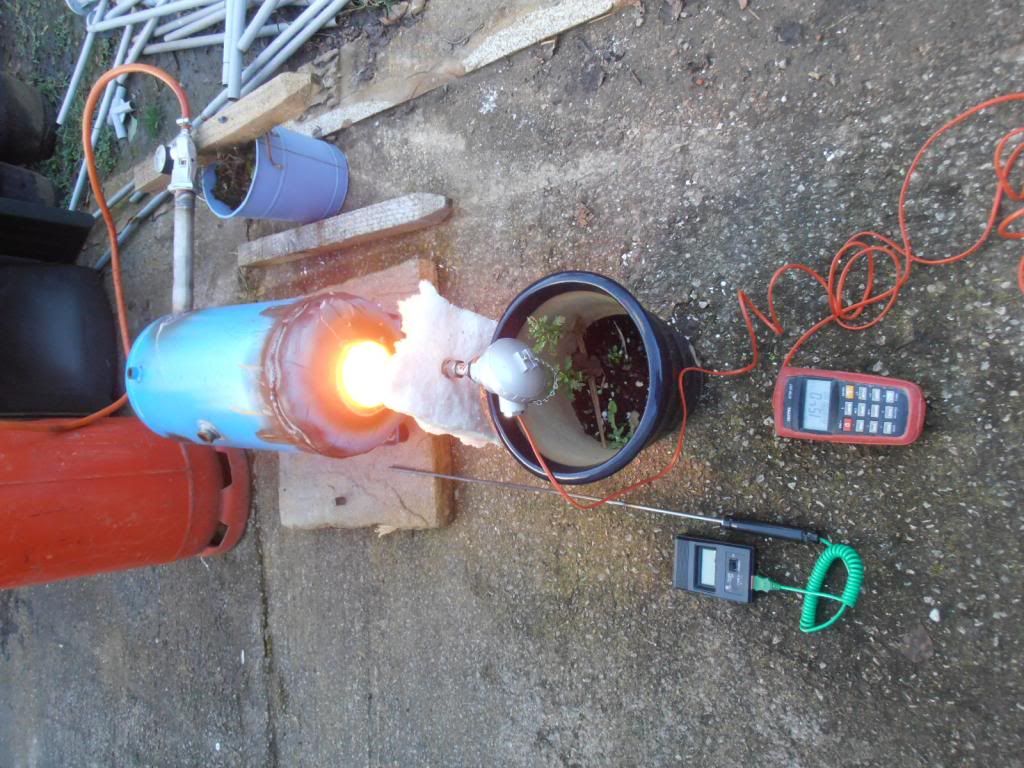
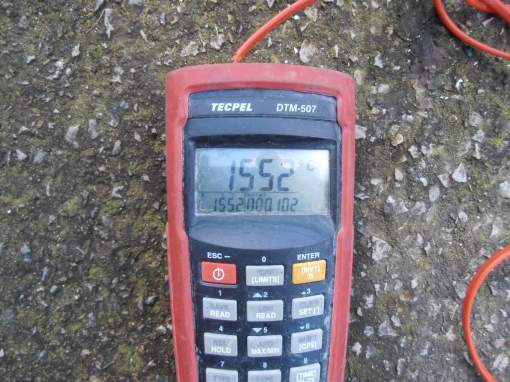
I've measured actual forge temperatures of over 1550 degC ( 2822 degF), but have not really tried to push for any higher. It's hotter than I'm ever likely to need and I don't want to risk an expensive Platinum-based thermocouple chasing unnecessary temperatures. In all honesty though, I don't think I'd get much above 1600 degC, even on a good day, without going significantly bigger.
I was primarily interested in covering the full range of temperatures useful for bladesmithing, from Austenitizing at around 760 degC (1400 degF) to welding at 1320+ degC (2400+ degF) with a single (relatively) cheap-and-cheerful setup that a novice could build with limited equipment.
Near the top of the temperature range:
And towards the bottom end of the range:
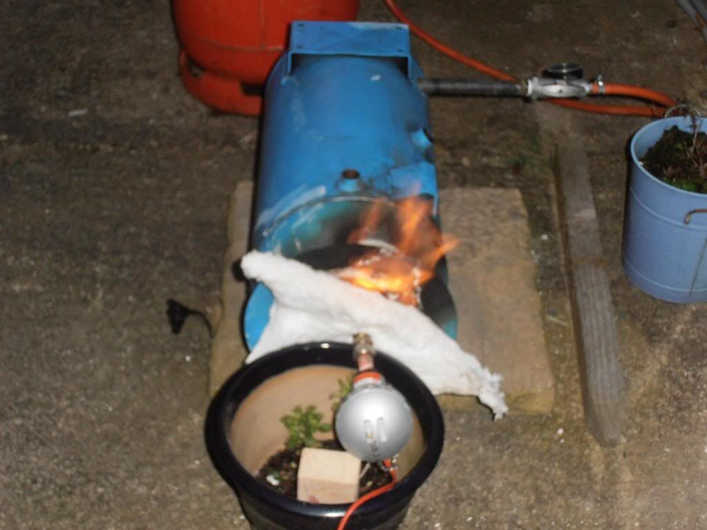
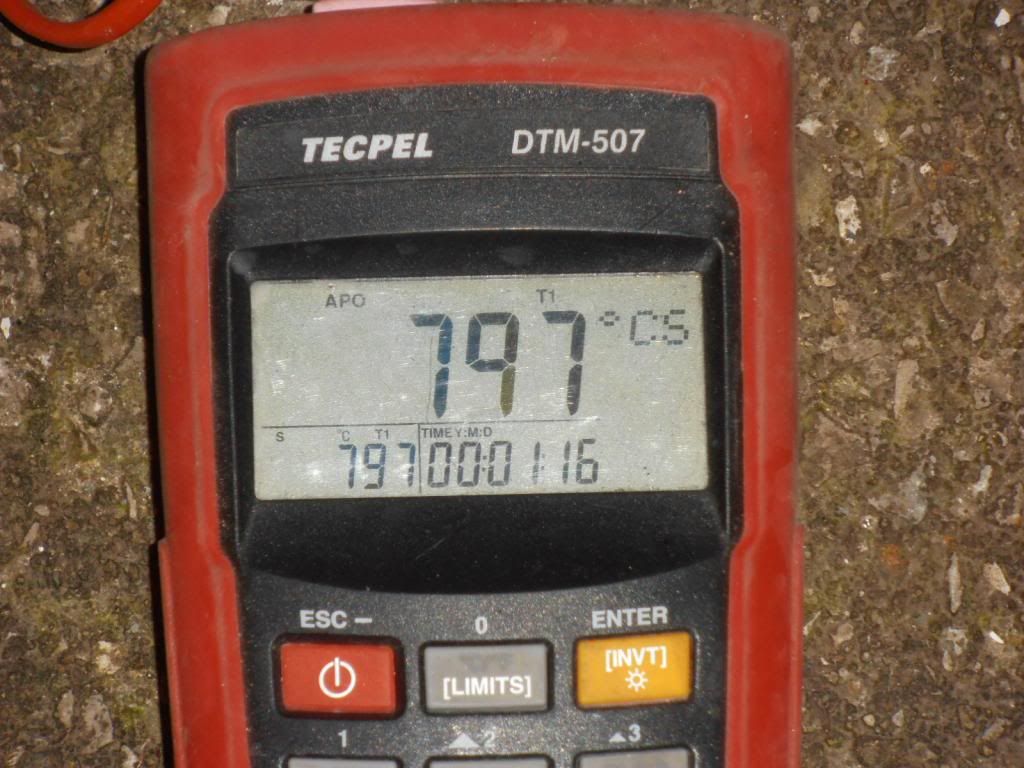
I was trying for 800 degC (1472 degF) and 797 degC is 1466 degF. Incidentally, the minute and sixteen seconds shown is because the pyrometer has autoshutoff after some arbitrary period of time and I'd switched it back on a minute and sixteen seconds earlier.
The Mikey burner had seemed difficult to build for a beginner without a fairly well-equipped shop, while the design of the Frosty T-burner seemed to present difficulties in arranging a choke that would give the sort of fine and progressive control that makes it easy to hold an Austenitizing temperature (here in the UK, we have easy access to O1 Ground Flat Stock, but most other blade steels are difficult to find and often involve high international shipping costs, including 1084, so being able to soak for the time O1 needs can often repay the extra cost of a burner that will do it). I'd been using Amal injectors at work for over 20 years, but had no idea what they cost. When I found out the price, it became a no-brainer to use them. IIRC, the last 1" injector I had cost around 55 GBP delivered (and including 20% Value-Added Tax), equivalent to about 85 USD. Not cheap by hobbyist standards, but it seemed very good value.
-
In the first post, you say you've used the same size jet (.035 MIG tip) in the 3/4" and 1" burners.
You will have a much leaner mixture in the big burner: more air for the same gas flow.
Assuming the 3/4" burner was about right, upscaling to 1" should have the gas jet diameter increase in direct proportion to the pipe diameter.
Try a .045 MIG tip and see if it's better.
-
It is possible, but not at all easy.
The problem you are up against is gas pressure: household NG is usually delivered at a pressure measured in inches of water column. Here in the UK, it's normally 8" WC, about 0.3 PSI.
In a NA burner, the gas velocity through the gas jet is what causes the air to be drawn in, and the gas velocity is dependent on the gas pressure. Most NA Propane forges seem to use 0-30 PSI regulators, giving up to 100 times the pressure likely to be available from your NG line (I actually use a 0-60 PSI Propane regulator).
The energy density and air:fuel ratio differences that Charles refers to pale into insignificance against the pressure problem.
If you have a high-pressure NG feed (usually only for large industrial users), a NA forge is not particularly difficult. Finding good instructions for a self-build is likely to be harder though, since most use Propane.
If you really want to use NG, a blown burner can work well, even on low-pressure NG.
I'm not sure what your rules and regs will require. Here, portable Propane-fuelled equipment has fewer restrictions on what can and cannot be done than fixed NG equipment, so the legal and insurance issues tend to rule out NG forges for the DIYer. Fully-approved NG packages are available of course, but carry a pretty hefty price tag, so tend to be used mainly in industrial and educational applications.
-
They look like they should do the job, but I'm always sceptical about grip being maintained with cyclic loadings in a brittle material like concrete. In a previous life installing heavy machinery, we had lots of problems with lots of different anchors right up until we started using resin anchor systems.
Some of these are remarkably cheap now and they really do work very well.
If you need specs, approvals, etc, Simpsons seem to make a number of them. If you are building the foundation, you'll have control over the material you are anchoring into, so it probably makes sense. If you are working to code, you'll probably have no option. I don't see yours as a critical application insofar as nobody will die or get maimed if the anchors fail.
I only usually get to fix stuff down to something that's already there, and don't usually have the materials spec for the concrete I'm anchoring into. As a result I buy the stuff pretty much on price. I tend to use long lengths of studding (allthread) to ensure there's enough adhesion, even with the worst-case hole-cleaning and lowest resin performance. I usually use Polyester resin because it's usually the cheapest and I don't need to consider chemical resistance where I use them. I buy High Tensile studding (allthread) in grade 8.8 (we're metric over here), usually Bright Zinc Plated (It's mainly laziness: the BZP stuff tends to be clean and the unplated stuff tends to need the protective oil cleaning off).
Over here, the standard resin cartridge is 380ml and needs a special cartridge gun. There are also small cartridges for use in a standard mastic gun, but they work out very spendy for any but the smallest job.
I find the resin squidges out of the hole when the studding is inserted and fills the gap between the surface of the concrete and the bottom of the item being bolted down for a useful distance around the hole. It usually helps to hold the washer down as the studding is inserted to help to force the resin onto the gap. The resin squidge means that even if you only had 3 points of contact when you placed the machine, you'll have a point/area of contact at every hole once you've bolted it down.
-
This is probably just physics/chemistry at work.
In your burner tube, the gas/air mixture needs to be moving towards the forge faster than the flame-front moves through the mixture in the opposite direction.
As things get hotter, the speed of the flame-front increases.
In effect, it is normal. However, most people will get the pressure to where they know everything works pretty quickly and stay ahead of the problem.
One of the balances that needs to be found when sizing a burner is whether you can get the mixture speed up to where it needs to be in normal operation at a realistic heat input. If, to keep the burn where it should be, you have to run at a higher gas flow than you really need to run at to do the job you want to do, your burner is too big.
-
You are absolutely right Thomas: starting from scratch, a blown burner is very simple. There are lots of nice ones out there that work very well and are easy to copy well enough to get the performance required.
Making a NA burner that works even moderately well does need either a lot of luck, a good understanding of the process, or a good set of plans built quite meticulously. Preferably all 3. It is indeed much harder than making a blown burner.
I'd read post #6 above by the OP about hybridizing the burner to get extra air in (presumably for higher temperatures), whilst retaining the facility to run as a NA burner. It seemed to place unnecessary constraints on the design of a blown burner.
Thinking about it, I'm pretty sure I could make such a system work pretty well. However, I never would because I could get a similar effect with higher gas pressure, a smaller jet and a choke for less money and less effort.
I don't think I've actually seen many NA burners running lean (some certainly, but not most). The majority have had Dragons Breath, indicating a rich (reducing) forge atmosphere. That said, I tend to see bladesmithing forges, rather than blacksmithing forges.
-
There is someone in the States listing 3/4" NIB Amal Atmospheric Injectors on ebay. Search for "Amal Atmospheric Injector".
I think the jet sizes will be much too big for Propane, as they are Natural Gas injectors.
http://amalcarb.co.uk/downloadfiles/amal/amal_gas_injectors.pdf
I don't know whether Amal made a version with NP threads for the US, but I doubt it. As standard, the threads are BSP, which might be a minor pain.
When I was messing about with jet sizes for the 1" burner, I used a 1/8 BSP to M5 reducing bush and M5-threaded miniMIG tips. My 1" burner worked well with a 0.6mm tip (.023"), so a 3/4" would want a smaller jet. As .023" seems to be the smallest standard MIG tip, that option is out.
Burlen Fuel Systems supply carburettors for old, mainly British, cars. They certainly ship to the States.
Help with hammer power options
in Power Hammers, Treadle Hammers, Olivers
Posted
As the guys above have said, a VFD works by taking AC mains input, rectifying and smoothing it to DC, then synthesizing a Pulse-Width-Modulated 3 phase output. In simple terms, it does this by switching the DC on and off very fast. The clever bit is that it can vary the output frequency and Voltage to provide variable speed.
If you simply set it to give an output at your local mains frequency, it will work as a phase converter.
For most of us, it's just a black box, so it'll be doing the the same job as any other phase converter.
The single-phase-input VFDs take 230V in and output 3 phases at 230V phase-to-phase, which means they can only run motors that are wound to take 230V in Delta and 400V in Star (Wye).
In Europe, this means most 3-phase motors up to "about" 2.2 kW. Most motors above "about" 5.5 kW are wound for 400V in Delta and about 700V in Star to allow Star-Delta starting on 400V supplies (it's a way of reducing the starting current of big motors). In the 3-5.5 kW range, it seems unsafe to make any assumptions and you'll definitely need to check your motor rating plate.
There are several different types of phase converter and here in the UK, they normally incorporate a step-up transformer to go from 230V to 400V, giving 2 of the 3 phases. Then there's a static phase converter stage, which basically comprises a bunch of capacitors. This will give the third phase, but it is difficult to get the capacitors exactly right to give precisely the same phase-to-phase Voltages, particularly when the load varies.
To help balance the phases, often there is also a large idler motor, making it a Rotary Phase Converter. The Transwave MT3 is a Rotary Phase Converter.
Most phase converters seem to get used to run industrial 400V 3-phase machinery in home workshops. Often it is old equipment which cannot be rewired to run on 230VAC 3-phase and the old-school varnish in the motor windings cannot necessarily cope with the extremely fast Voltage rise of a VFD without breaking down. The safest course of action in this case is to use an RPC, as it gives a nice clean output waveform and you can be pretty sure it will not cause any problems..
There's some pretty good information on Transwave's website about Phase Conversion.
http://www.powercapacitors.co.uk/wp-content/uploads/2015/08/OD1_laymans_guide_converters_inverters_single_phase_supplies.pdf
The Transformer in an RPC is fairly expensive and the idler motor is also fairly expensive. Phase converters tend to be made in small numbers by small companies who largely sell to non-expert customers and need to support their products. As a result, they tend not to be cheap.
With electronics getting cheaper all the time, going the mass-produced VFD route is starting to look like a viable option for the guys who don't absolutely need their machine to be running to put food on the table, pay the rent, etc., and who are running relatively modern motors that can run on 230V 3-phase and have modern resin impregnation in their windings able to cope with the "dirty" VFD waveform.
They may even suit the guys who do need the reliability: the big-name VFDs are pretty reliable now with lifespans not far short of the motors they run. At work we tend to see them lasting 5-10 years of continuous running.
I'd expect the low-cost VFDs to be less reliable, but I've not used enough to get a feel for how long they last.
Searching for "4kw VFD" on ebay will find a good few Chinese-made HuanYang VFDs. Pricing is quite volatile at times, but they are currently available from about £120 delivered. It's not the whole story: you'll need to enclose the drive in an IP55 or better panel and provide it with control switches and power, but your £300 seems to be in the right sort of ballpark.
There are 2.2 kW and 3 kW drives as well, but with the HuanYangs I'd suggest getting a drive rated for at least the next size up from your motor.
The high switching frequency of VFDs can cause Electro-Magnetic Interference and it should be mentioned, though I've put together a few HuanYang VFD packages now and I'm not aware of any interference issues having arisen in the real world.
I'd have no hesitation in running a 25kg Anyang off a 4 kW HuanYang drive myself.