RockLobster
Members
-
Joined
-
Last visited
-
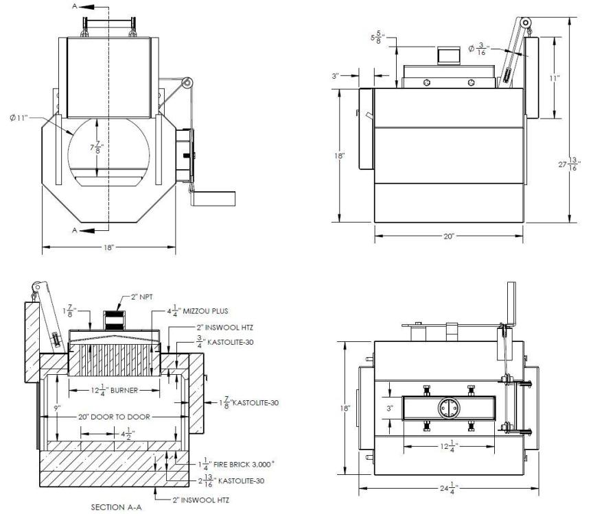
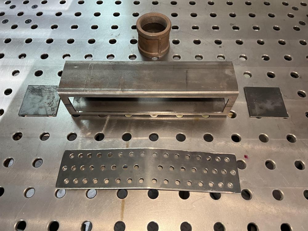
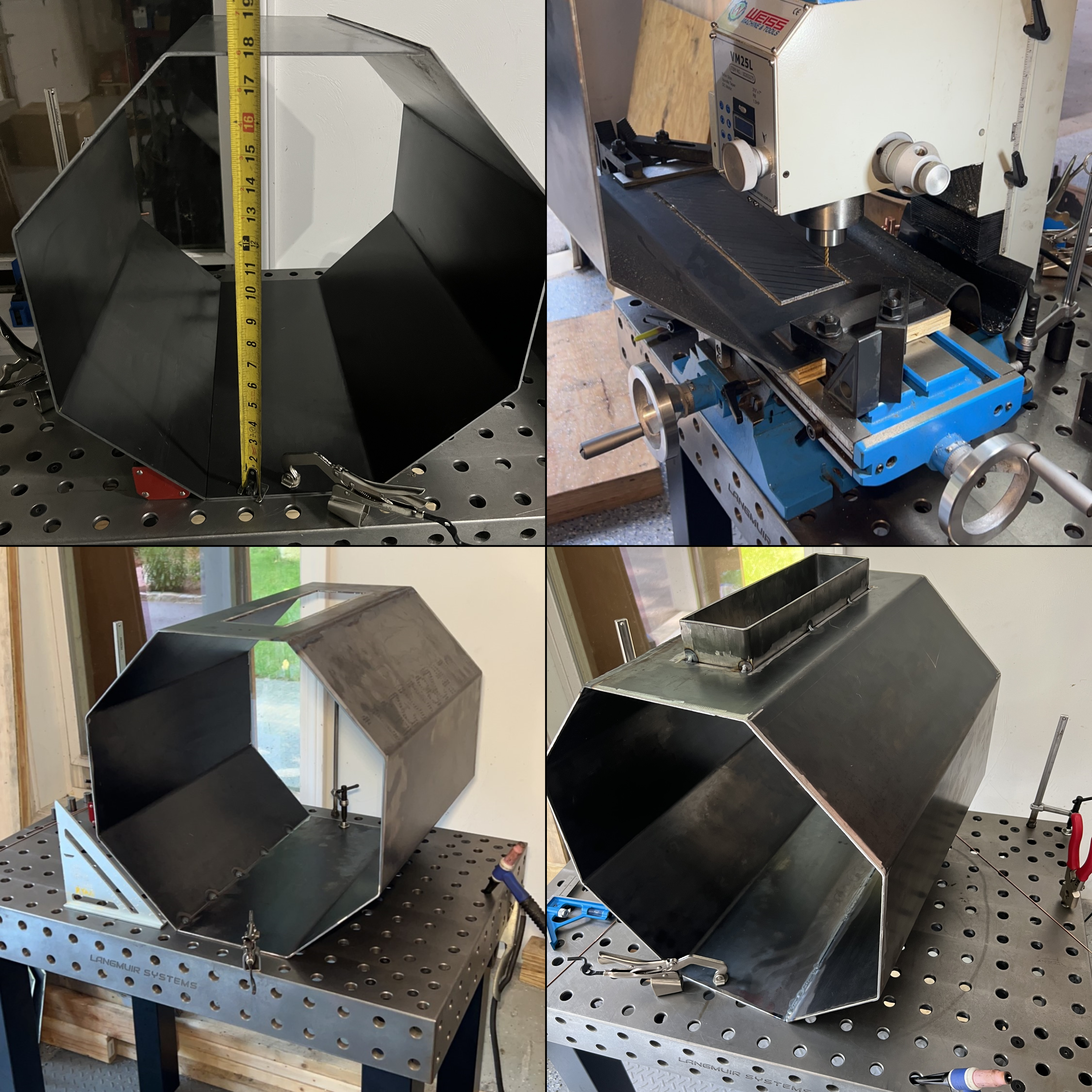
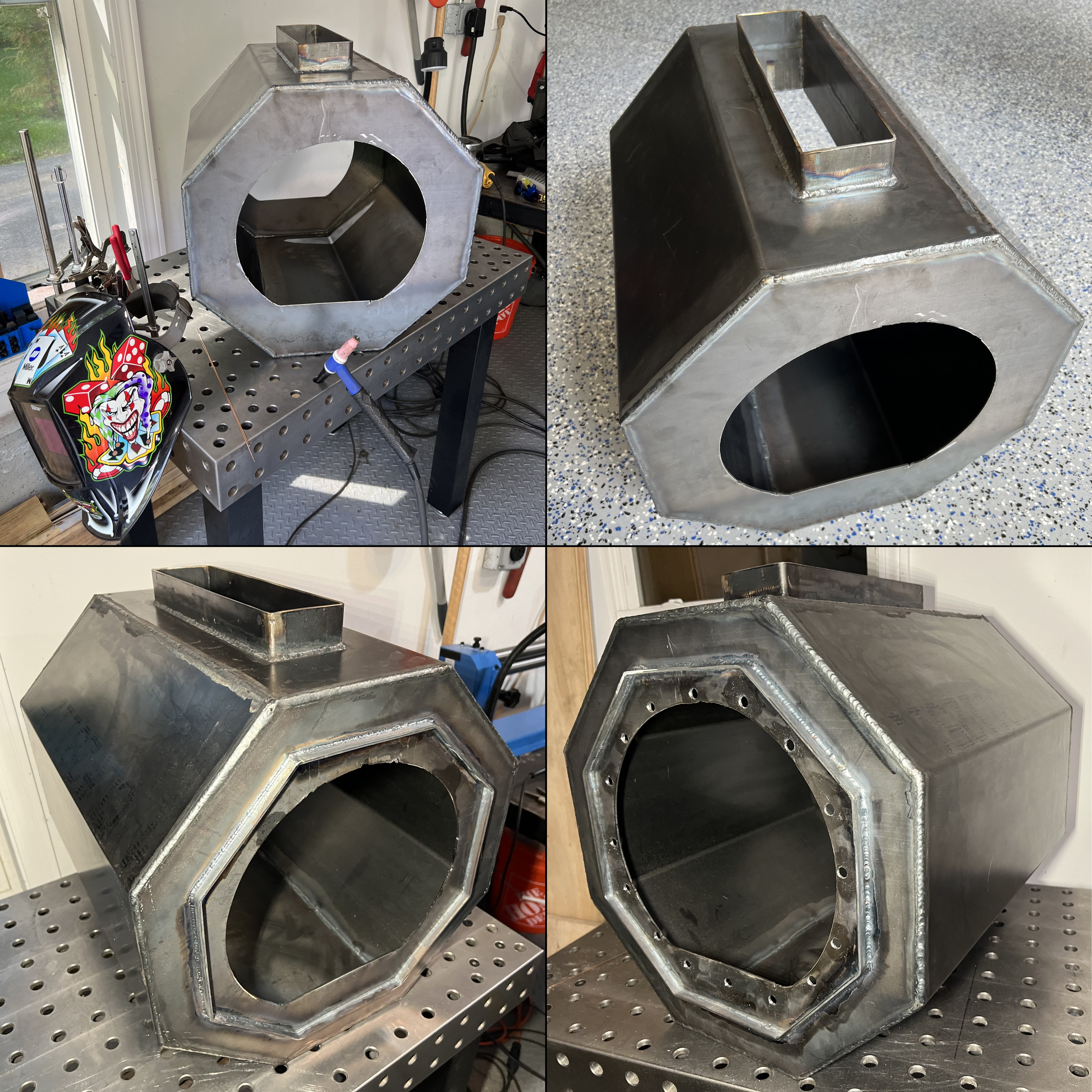
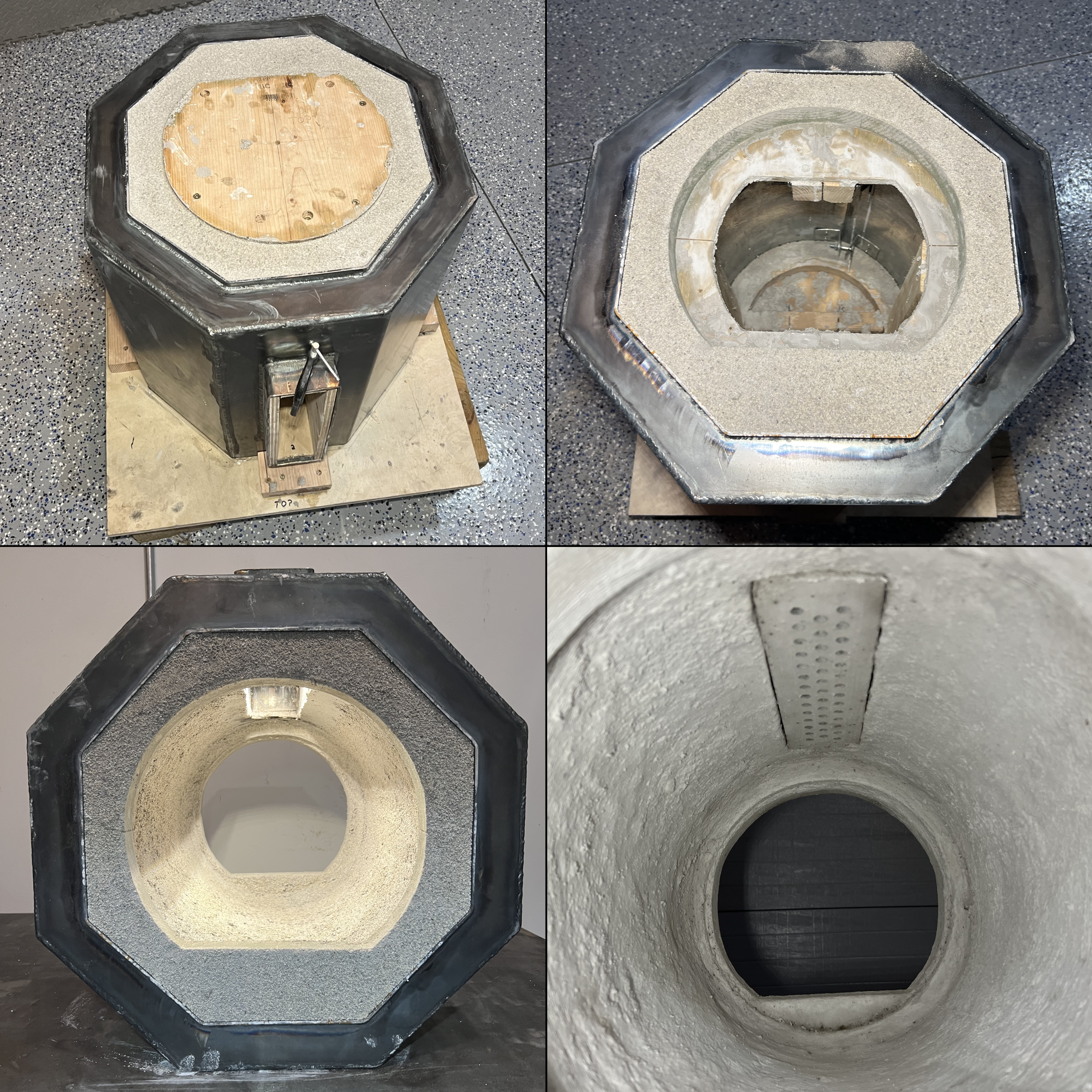
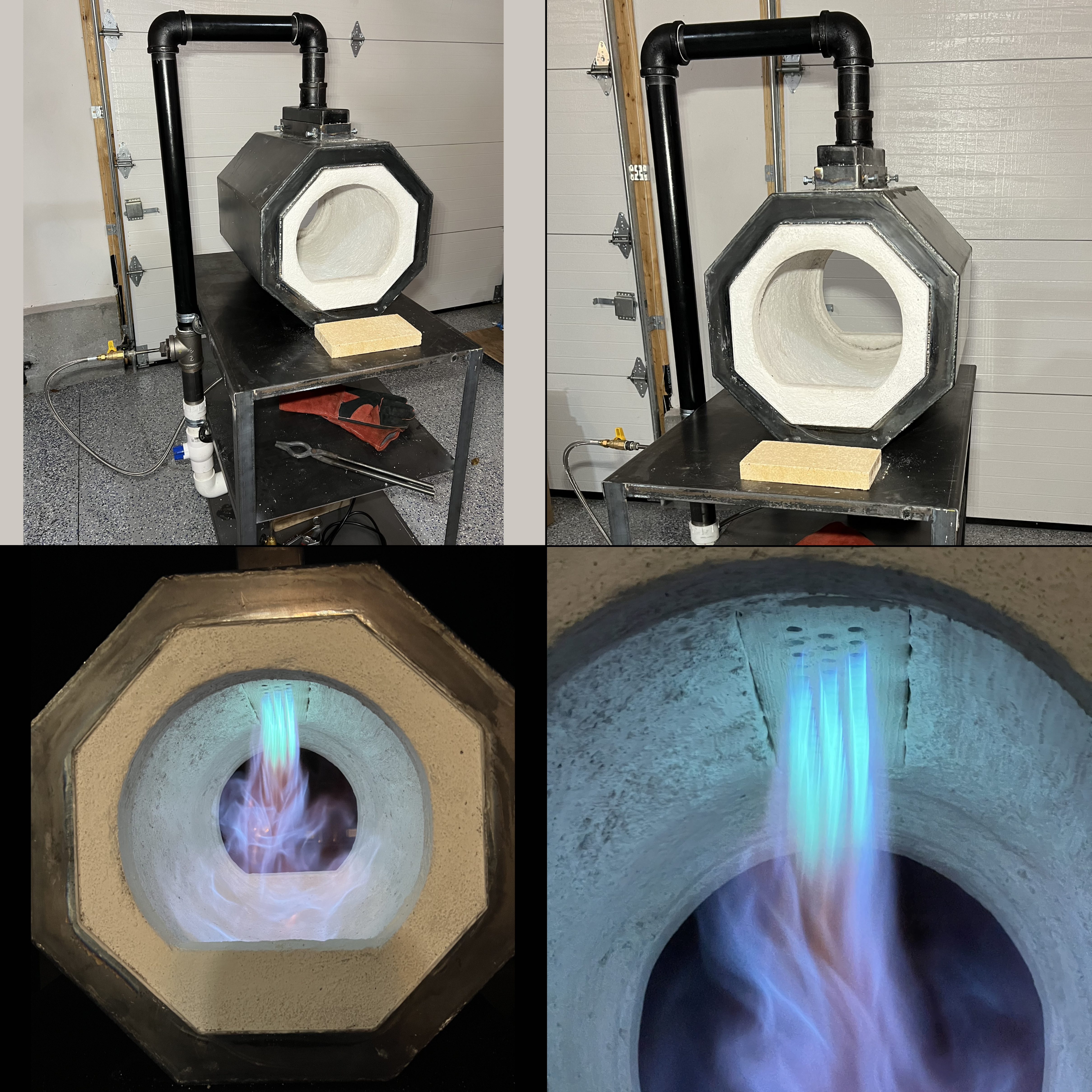
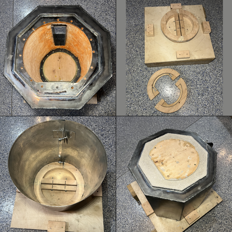
The forge build continued with the fabrication of the forge body shell. This was made from 11 GA steel plate, 11GA is overkill for sure but it’s the thinnest my work keeps in stock. I chose the octagon shape so the interior could be cylindrical while giving flat surfaces on the outside for mounting components. It can also be easily formed in a press brake and I think it looks great. I formed two halves by making three bends in each side. Next I milled out a slot in the top for the burner. I then set a collar into the burner slot extending on both sides. This will help to encapsulate the Inswool at the burner pass-through and provide a solid mounting point for the ribbon burner. I made two end plates for the forge body using a hand held plasma cutter and wood template to trace the outline. Then TIG welded all the seams with a continuous bead for an airtight seal. Next I added 1/2" flat bar in a matching octagon shape, offset 2” from the edge. This gives an easy and clean looking edge to the cast refractory at the outside face. Finally I decided to drill 7/16” holes around the edge of the opening. My thought is this will make for plugs of cast refractory that bond the exterior face to the interior, to help resist cracking and chipping on the exterior refractory. I’m hoping it won’t do the opposite and cause cracks under thermal cycling. With the forge tub weldment complete it was time to line it with insulation, I used 2” of Inswool, (actually 2X 1” layers). I coated each side of both Inswool blankets with rigidizer before installing. When I cut the blankets to size, I slightly oversized each dimension by about 1/2" for a tight fit when installed. Then it was on to making a mold to cast the refractory. One thing I would have changed if I did this again was to make the center of the forge a straight cylinder. I was initially thinking it would be a good idea to have it neck down as to have a lip to help keep heat in the forge. However this made the mold a real bear to make. It had to be made in sections that each disassembled to fit inside and then reassemble in place. It took me nearly as long to fabricate the interior mold as it did to do all the metal fab for the forge body. I used Kastolite-30 refractory mortar, about 1/2" thick in the interior cylinder walls and 1" thick at the end walls. After letting it cure for a few days I removed the interior mold. This was also difficult and I ended up cutting it into pieces to do so. The up side of this laborious molding process is that it left a very clean looking casting in exactly the shape I had intended. I really wanted the opening to have the semi-circle shape with a flat bottom. My thought is this will give a nice spot to rest work without it rolling to the center. Finally I applied a thin coating of Plistix 900F to finish the refractory surfaces. With the forge body complete I installed the ribbon burner and was please to find it fit like a glove. I also fabricated a custom table for the forge to sit on. This made it easier to mount the blower and provided a protected area. I plan to make an adjustable work holder on the table at a later time. At this point I could finally fire the forge! I’ll admit I don’t have a trained eye for fine tuning the fuel/air ratio but I’m extremely pleased with the function. It seems like I have a good range of adjustability which is good because it’s quite thirsty on a higher setting. I fired it for just a short time at first to allow the refractory to cure. After repeating this a few times, I really let her rip for about an hour. I have just a K type thermocouple, I’m sure it’s not particularly accurate but I took readings of about 1,700 deg (amazon says it’s good to 1,800 deg F even though most other K types are not rated for that). Regardless I will need to make the doors for the forge before I really know what kind of temperature it can achieve, I’m just hoping I can do forge welding without a hydraulic press. I did put a piece of mild steel in there during the test and it achieve a nice light red/yellow color.


-
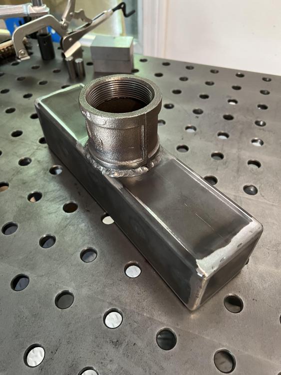
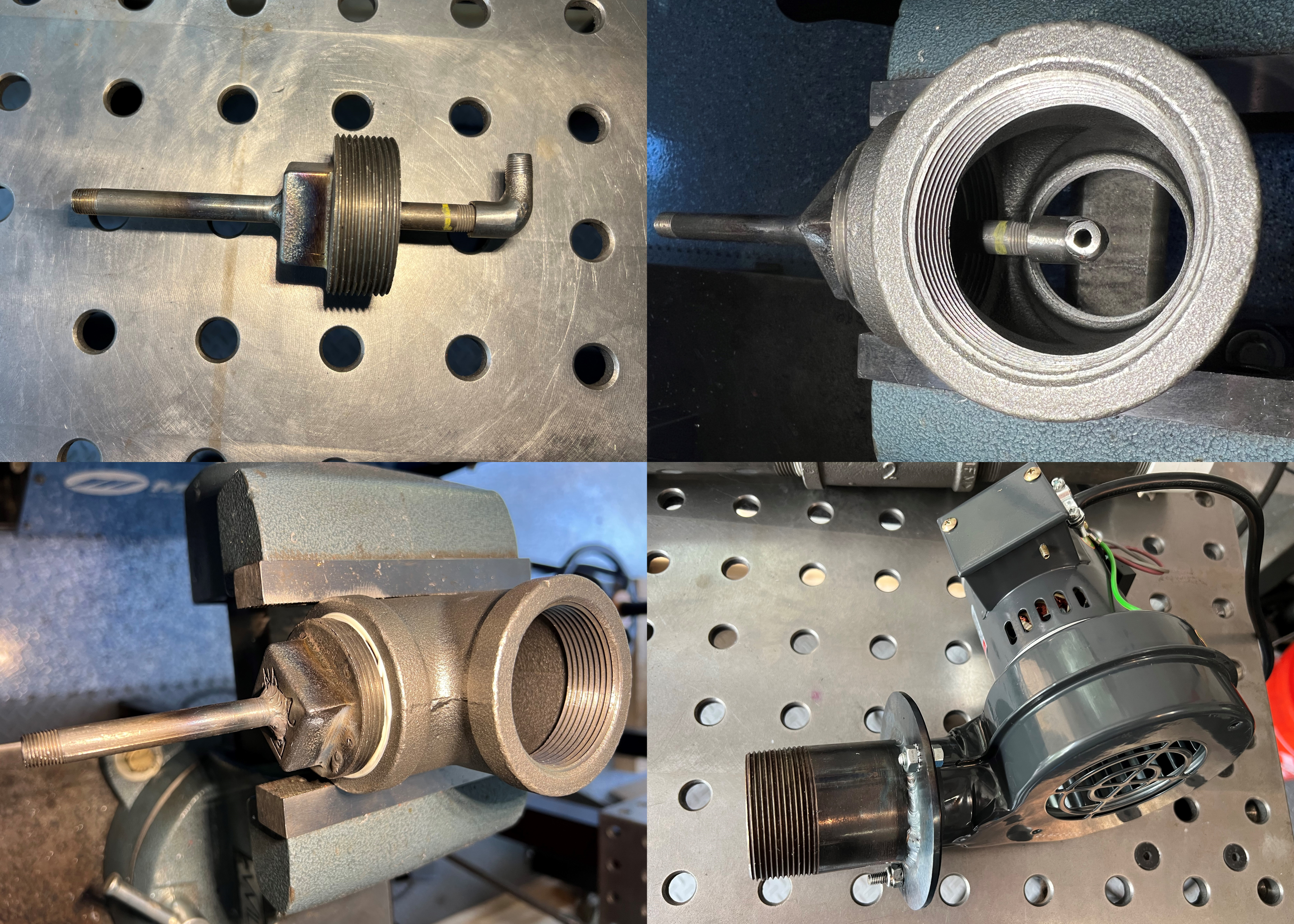
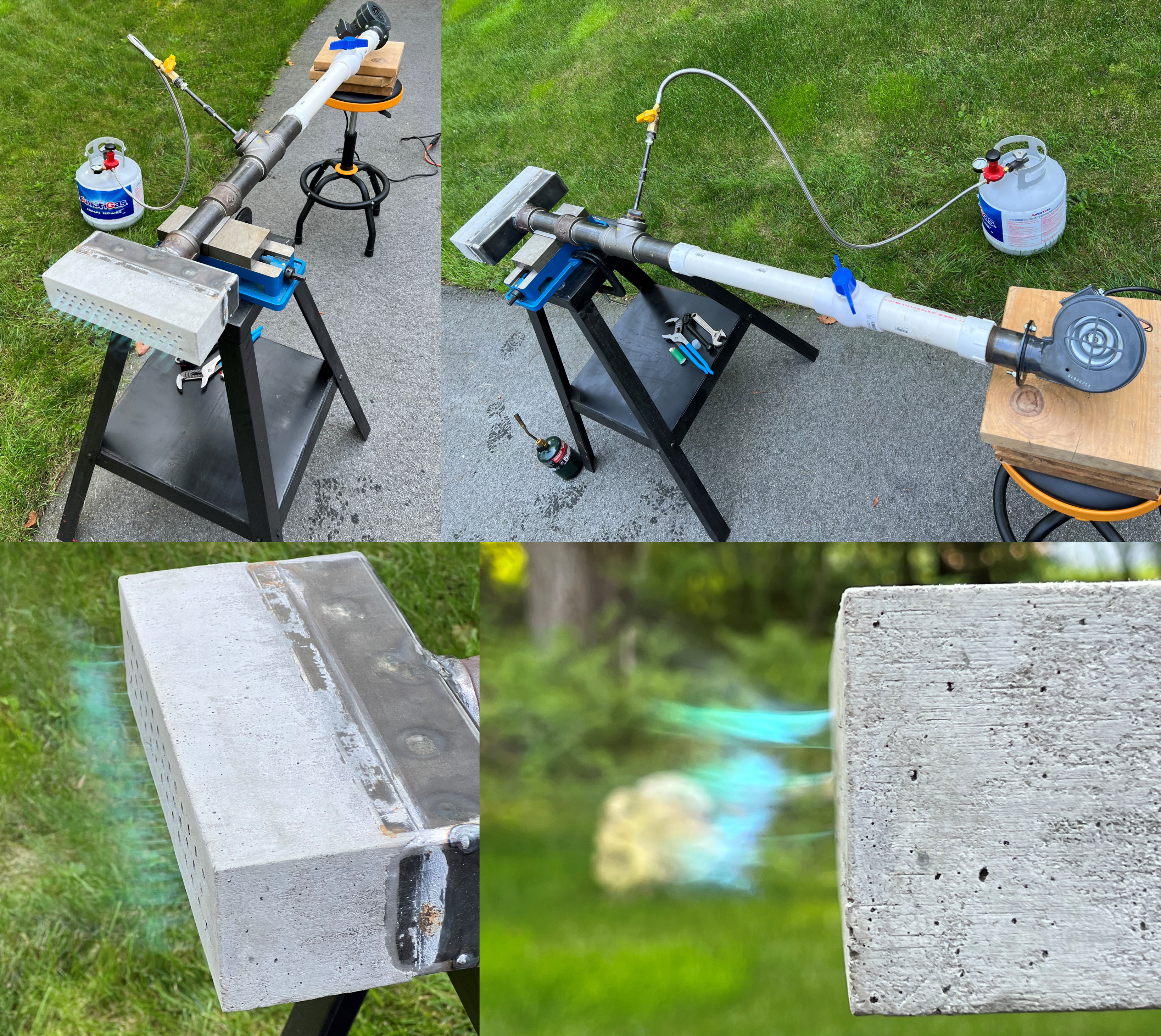
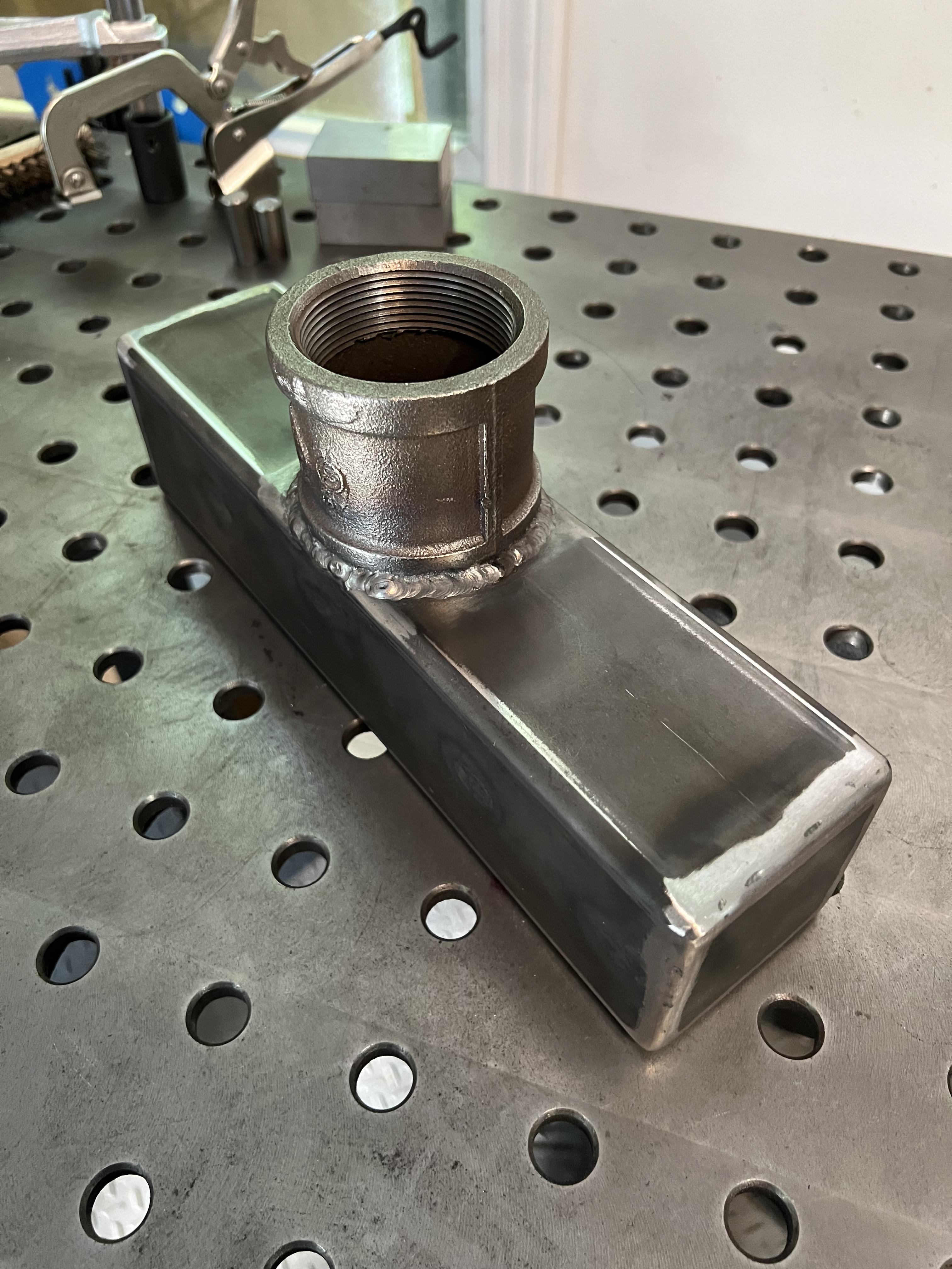
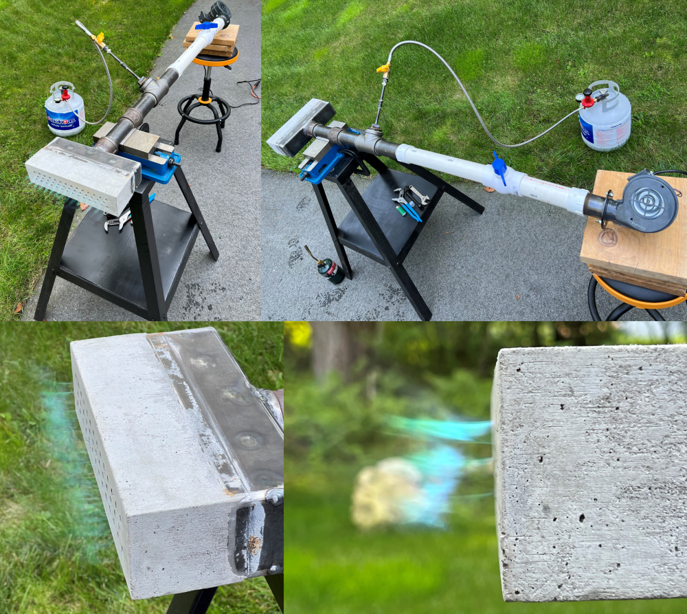
Gas nozzle: Next I fabricated the nozzle to inject the propane into the air stream. The main air pipe is 2", For the gas inlet I used 1/8" pipe. I drilled a hole in a pipe cap and welded the 1/8" pipe to it. I used a 90deg 1/8" elbow centered in the 2" tee, also ground it down a bit to try an minimize the flow restriction. You can also see a picture of the blower I have with a flange to 2" pipe adapter. I had purchased this blower some time ago and was concerned it might be undersized but figured it's what I had on hand and might as well give it a go. Burner Test Fire: At this point the burner had been drying for about five days and I was ready to test fire it. Note that I used a 2" ball valve to control the air flow and 3/8" ball valve for the gas. It seemed to work excellent. I admit I don't have a trained eye for exactly what a proper flame should look like. I found the blower could supply enough air to achieve flame liftoff and even blow it right out. After a bit of fiddling I found a gas to air radio that looked good (to my untrained eye). This is what you can see in the pictures below. Note the ball valve for the air was about halfway closed, so I'm thinking this little blower might just be enough? Anyhow, this is very positive progress and I'm now very eager to get the forge body build! I also realize the flame is very hard to see as I wanted to do this outside. I plan to fire it again at night when I can see the flame better and further experiment with the air to gas ratio.

-
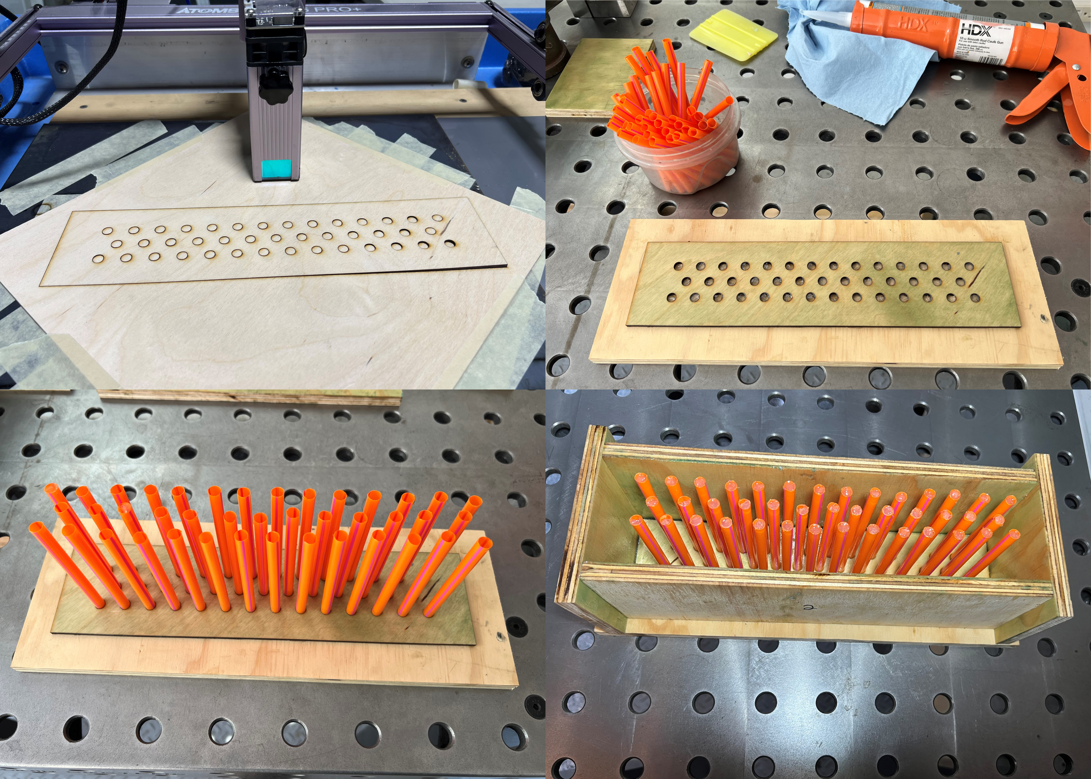
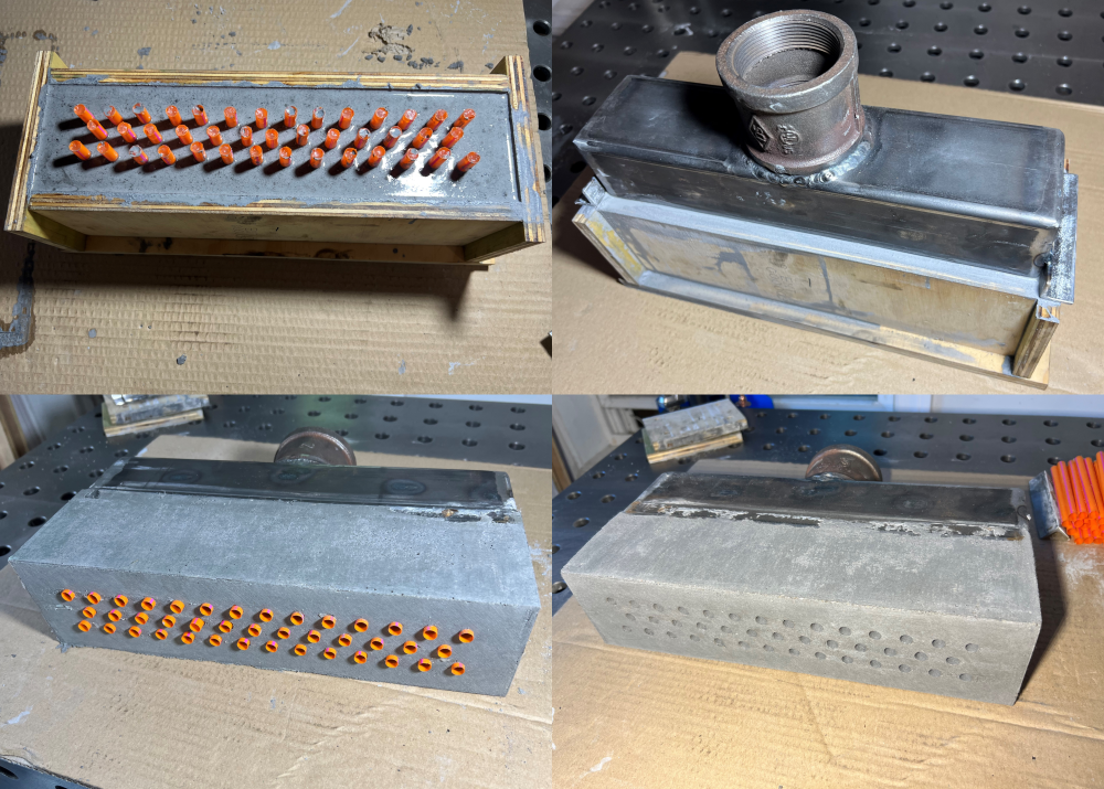
Update: Burner casting, gas nozzle, & burner test fire Burner mold: Making the mold was fairly straight forward, sides are cut from 1/2" plywood. I used a "laser" (cheap diode laser) to cut 1/8" plywood so the straw layout would be exactly as modeled with CAD. This saved me hours of drilling. I then coated all the inside surfaces with axle grease and let it soak into the plywood. Note that I did reduce the thickness of the Mizzou. Originally I had it at 4.25" thick and I reduced that to 3.5". Casting the burner block: The casting also went well, I probably mixed a little too much water in the Mizzou but I don't think that was any problem. I added it in four layers taking time to stir the Mizzou around the straws and vibrating with a drill (bent steel rod in the chuck). Then set the burner weldment in the mold and waited two days before removing the wood. The straws worked perfectly pulling right out of the casting, no messy crayons to drill/melt out :).

-
I’m starting to wonder if the 40 nozzles is a bit excessive. I see other people using 32 for a similar size burner. However you bring up a good point that holes can always be plugged up after the fact. My thought on the 40 holes is the combined area (cross section) of the nozzles should be similar to slightly less than that of the inlet pipe (2” SCH 40). At 41 the combined area (2.90 SQIN) is still less than that of the 2” pipe (3.36 SQIN). I’m certainly not looking for 2 FT of dragon’s breath at the forge door. Side note: plenum baffle open area is 3.68 SQIN (5/16” hole X 48) 11 GA is certainly overkill but it’s the material I can easily get from my work. Thank you for the detailed comments, I certainly appreciate the advice.
-
I want a good sized forge, one with a rather wide mouth. I plan on making decretive iron railing sections and also want the ability to forge a good sized axe head. It’s similar in volume to one I’ve used before. I’m more hoping that I will find the burner is well sized for the volume. No power hammer but I've already got ideas on making a press as my work does hydraulics. I plan to leave ¼” gap. I’ll mill down angle iron for make the track. Good advice, I was thinking I may need to alter the casting a bit for this reason. I’m planning to use an interior form while casting the refractory. The casting will probably need to be done in two parts to get the form out. I’m hoping that won’t leave a seam between the two cast sections which would be prone to failure. Plan is to tighten the bolt to apply enough friction to hold the door open. If I don’t like how that feels I can add a counter weight or locking mechanism. I will probably never run the rear door fully closed although I show it that way in the model. The baffle holes were made to give more open area than the input pipe as to not cause too much restriction. I could make the burner block a little less thick maybe 3” or 3.5” at a minimum. My assumption is the 41, 0.30” holes should allow for pretty decent flow. I will certainly need to play around with air & gas flow. Hopefully that doesn’t involve finding the point where blow back is possible. With air & gas mixed in the plenum I’m sure there is a danger here if the flow is too low. Anyhow the burner is designed to be replaceable if I find this one is simply no good.
-
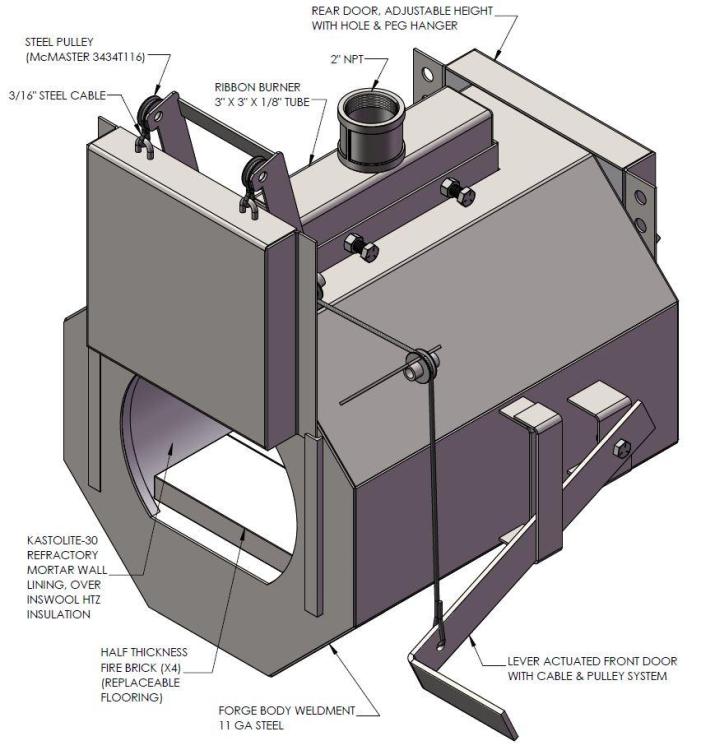
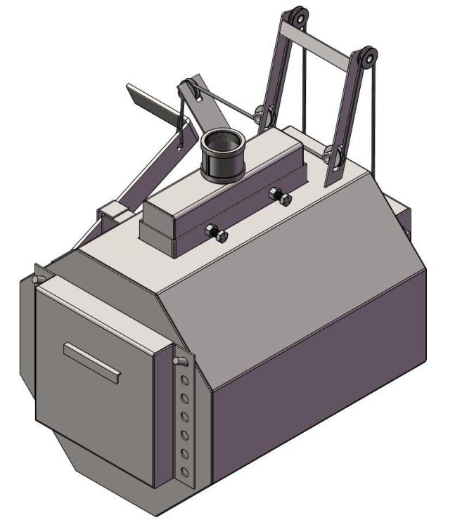
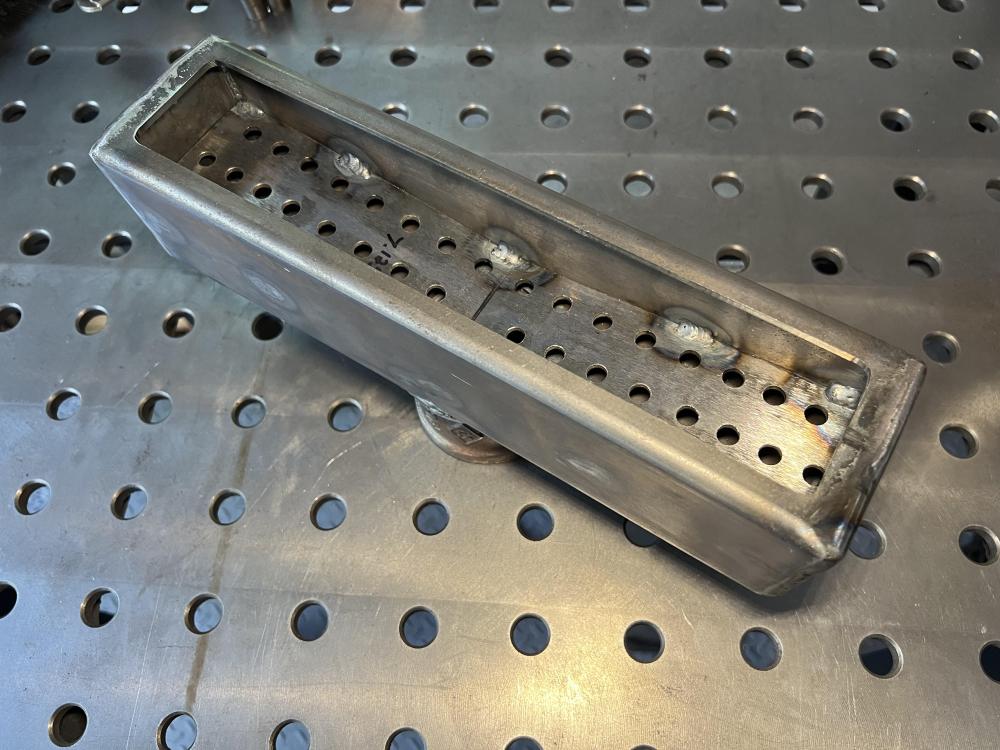
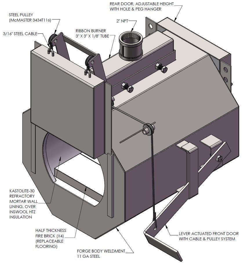
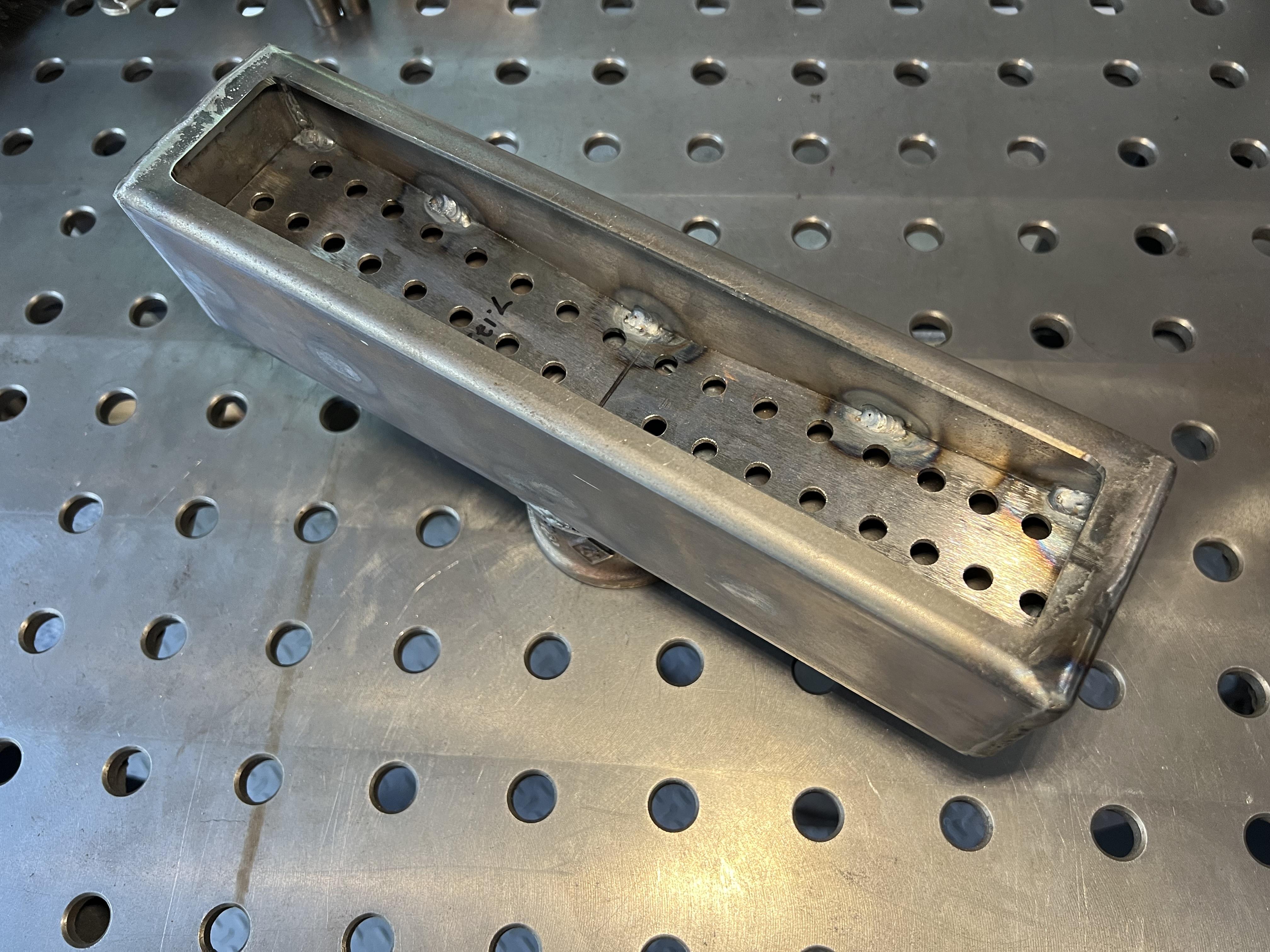
I’m in the process of building a forge and plan to use this thread as a place to document this build. Please feel free to use any of this information or provide helpful comments. A little about me and my thoughts for this build: I’m relatively new to smiting. I’ve taken a number of classes on blade making and blacksmithing but now the time has come to set up my own shop. This is a hobby for me but I take pride in having a quality setup. Initially I planned to buy a middle tier propane forge but I enjoy fabrication and thought I would enjoy building my own forge to my standards. After some research on various forge styles I settled on a ribbon burner propane forge. The inspiration for the design comes from a forge I used at The Steel Yard in Providence RI, so I have a good idea of the functionality I’m looking for. It may be slightly more complicated than is necessary but as I said, I enjoy the fabrication process. The initial design (REVA): My initial thoughts for the design are as follows, this is likely to be subject to change as I get deeper into this project. I have access to CAD (solidworks) so I’m able to fully model this before I get to building. I also plan to make a full drawing set and post it here for anyone to use, once the design has been proven to work. The forge body will be formed from 11 GA steel plate. Two halves welded together to form an octagon shape 18” wide with an overall length of 20”. Insulation will be 2” of Inswool covered by ¾” Kastolite-30 refractory mortar. The floor is sized to allow for (QTY:4) half thickness fire bricks to be placed as a sacrificial floor and easily replaceable. The front door will open vertically on a cable pulley system. Right now I’ve got a handle mounted to the side to actuate the door but this may change once I see how I like the function. The rear door is a less complicated peg & hole hanger system and will have a removable handle so it can be moved while hot. Burner: The burner body is a 3” x 3” x 1/8” tube, 12” long, with mixing baffle, and 2” NPT pipe union. It will be cast from Mizzou using the straw method with (QTY: 41) 0.30” holes. The burner slides into the forge and bolts in place as to be removable for future repairs. Forge Stand & Blower: I also plan to make a steel table for the forge to sit on which will hold the blower. Design for this to come later. So for I have fabricated the ribbon burner weldment assembly.