Skidpad13
Members
-
Joined
-
Last visited
Everything posted by Skidpad13
-
Have you guys checked out Colin Peck's "The Artful Bodger's Waste Oil Furnace"? He has been pretty successful with an oil burner for a casting furnace. I have his book but only got it recently so I have not had a chance to do a build. Exhaustive reading & research will be completed first of course.
-
I feel both enlightened & a little woozy from all this knowledge. Mikey, you are the best kind of wizard there is. Thanks!!
-
Mikey, although it is now "old tech" I am going to finish your earlier design burner (with your clarifications to the dwgs I posted last week) and document the build process both on video & with updated mechanical dwgs. That being said, I'm very, very interested in the 3D print concepts & will follow that conversation with great interest and anticipation. You guys have forgotten more about burners and FAM theory that I can fit into my brain housing group. On the subject of ordering nozzles from Amazon, I got confused at first & thought that you meant the actual 3D printed assemblies were available. However now I realize you're referring to the hot end nozzles. I have a bunch of E3d nozzles from a dual extruder build I was pursuing a few years ago. Now I just have to find that box... Thanks again for everyone's humor, patience, & wisdom. Cheers!
-
-
Mikey, following up on this. If using the 1/8" schedule 80 nipple, how critical is it to grind the threads off the end that the MIG contact tip will be threaded into? If the idea is to streamline, I would think that both these threads and the transition to the tip should be as smooth & gently tapered as possible. Thanks for indulging my neuroses
-
Twigg, you're wise words ring true. Architects know a little bit about too many things. It usually ends with me diving into a subject and emerging a few months later with a deep respect for those who've been doing it a long time. The thought had flashed by as I was finishing that last post and my brain said "squirrel!" so I tacked it onto the end without the normal amount of consideration I'd give. I'm going to spend a good amount of time reading & listening on this new-to-me subject. Then I'll draw up what I think I understand and see how that works. There are lots of incredibly smart folks on here and I have no problem following in the path someone else has already worked to clear.
-
Thanks to everyone for your excellent clarifications & detail. That being said, my head is now exploding with the 3D thread (so thanks for that, ha). My son and I built a Prusa i3 with a 12"x12"x12" build volume back in 2014. I haven't run it in a few years as it started developing a nasty habit of going out of level during bigger prints. So, we're still going to build the burner in the drawings above to finish what we started. However, expect to see me lurking with questions about the new tech. Holy cats, I mean seriously! 3D flexibility combined with high-temp ceramics for parts? I have Colin Peck's book on waste oil furnaces that I was going to open up later this year. Now that I see the possibilities of ceramic & metal casting I'm losing my mind. This all feeds my creation addiction way too much. It's similar to when I was deep into homebrewing. I couldn't tell which I preferred more; making the beer or drinking the beer. I know that I have problems and I promise to see a specialist about it very soon. Thanks everyone! Out of curiosity, has anyone used a computational fluid dynamics (CFD) modeling program to prototype expected mixing flows in the 3D nozzles? I apologize for asking this question completely blind since I haven't had a chance to read through the whole thread. I just thought I'd ask since I have some experience with CFX4 from work I did some years ago. I can't wait to dive down this newly discovered rabbit hole...
-
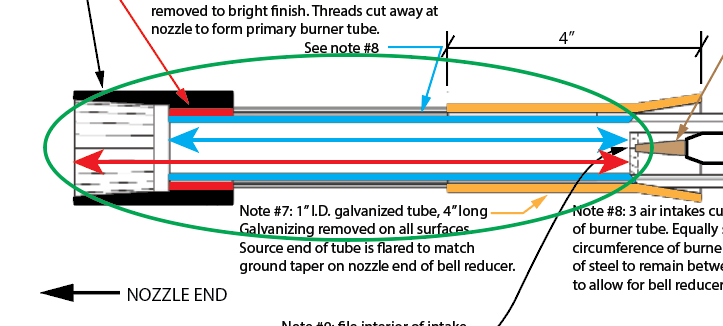
Mikey, thank you so much for these clarifications! I apologize for missing your comments in the book re: odd-numbered intake openings, I'll be more diligent going forward. I understand now that the step ring serves to give the enlarged opening for gas speed reduction so the taper in the SS nozzle end is no longer required. I'll eliminate that from the build. I had intended to also ask about the one thing you have already clarified, the burner tube length. I want to further clarify this for my all-too-linear mind. In the attached image, should the length of the tube, at 9x inner diameter, be measured from the outer end of the nozzle (red arrow) or from the tube end where the expansion/step ring allows for gas/air mixture expansion (blue arrow)? Finally, I truly appreciate your attention to this older design. I've read many posts so I'm guessing that the design currently taking the fore is the ribbon burner? I'm going to follow a similar documentation procedure for Frosty's NARB but I want to go see Wayne's forced air clamshell version before I go down that road. Cheers! -Paul
-
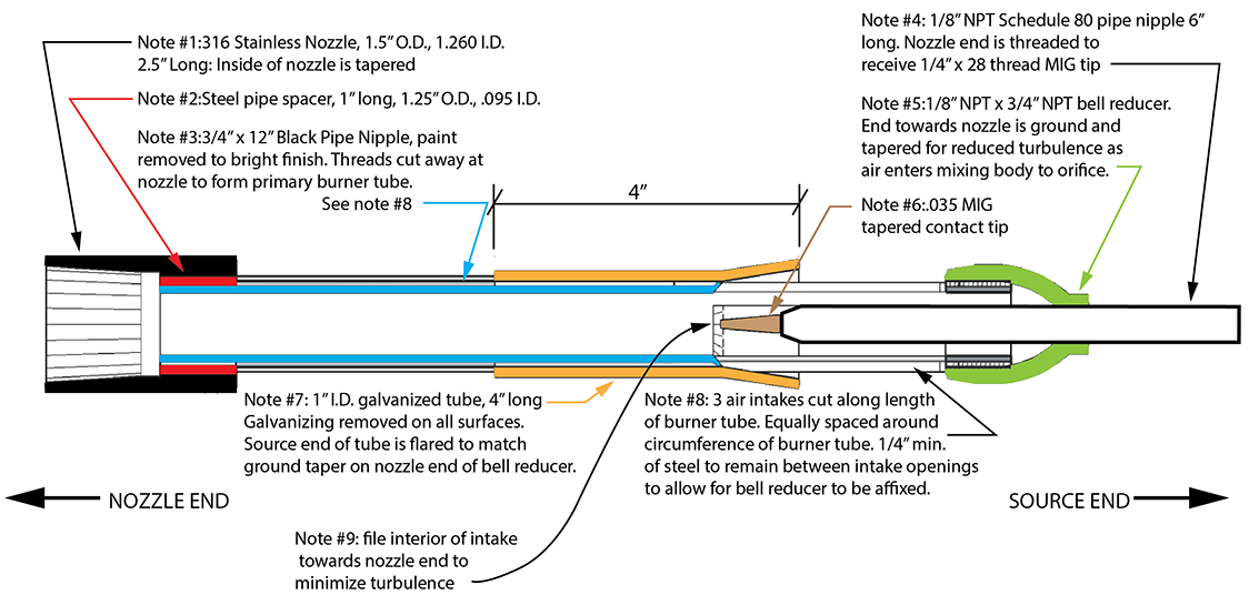
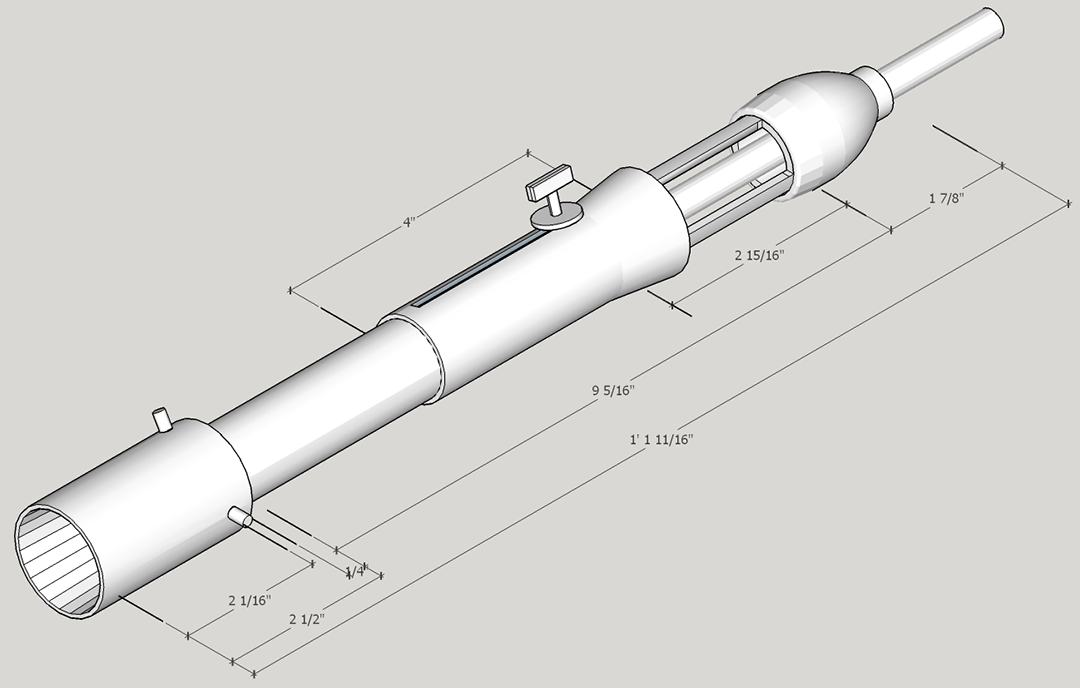
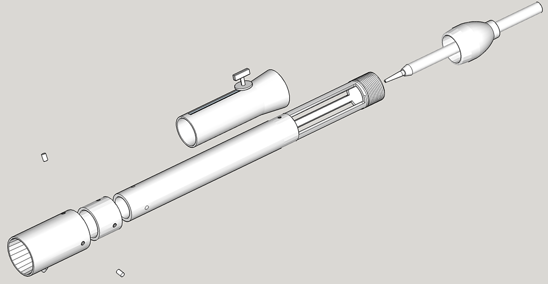
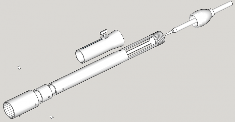
Good evening everyone. I've scoured the thread as much as my eyes can bear. Likewise, I've been re-reading Mikey's book over and over. I have picked up that there have been some modifications to the original designs as presented in the original book. Some of the modifications I have been able to find are: (A) change the number of intake openings to an odd number in order to reduce cross currents, (B) ensure that the length of the burner mixing tube is between 8-9 times the diameter of the tube and (C) there may be some builds that benefit from a smaller orifice opening than the .035 tapered contact tip. So, with these specifications in hand, I've documented the most current version of the design as best I can assemble it in my mind. Since my day job is as an architect, I couldn't help but to lay this out in the computer first where it costs less and saves time to make changes. If this entire exercise has already been completed and I just missed it please disregard this post and kindly direct me where to look as I have been unable to find this despite many searches and pages upon pages of reading. I would greatly welcome everyone's input, especially that of Mikey if you would be so kind. Although I know, especially from recent posts, that each build is slightly different and tuning and modifications will be necessary for each one, I still want to start off on the best foot if possible and then tune the build. One of the questions that I think I know the answer to I will state here for clarity: in optimal recommended configuration, where should the forward (gas discharge) end of the contact tip be in relation to the intake openings? Should it be in line with the forward edge, set back some distance? This is the one dimension that I feel is somewhat nebulous in what I have been able to find so far. This will drive the length of the accelerator tube connected behind the contact tip. In relation to this, does everyone find that forward/rearward adjustment of the accelerator tube in relation to the bell reducer, is essential? If so, my thought to solve this is to drill out the threads in the bell reducer and allow the 1/8" pipe nipple to move freely forward and back with three set screws providing both a locking mechanism for this as well as providing aiming screws for the centrality of the accelerator within the burner body. Please use the attached images, especially the section view with callouts and notes, to document my understanding of the latest generation as well as for edits, comments, corrections, etc... the axonometric view and the exploded view are just to show any 3D context that the section view may leave out. This and possibly a twin, will be used in a soon to be constructed forge. As many posts have suggested I am going to go and visit a local guru to see their setup before I begin on ours. I'm only a couple of hours from Wayne Coe as we are here in Nashville so I hope to visit him in the next couple of weeks and see his forge(s) before beginning to build ours. Thanks for any comments or advice, corrections, etc... I'm always humbled by the amount of wisdom and patience from the members of this forum. SF Paul


-
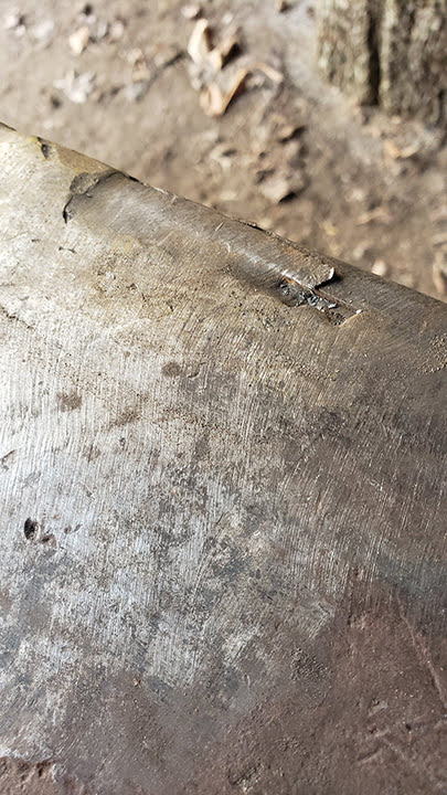
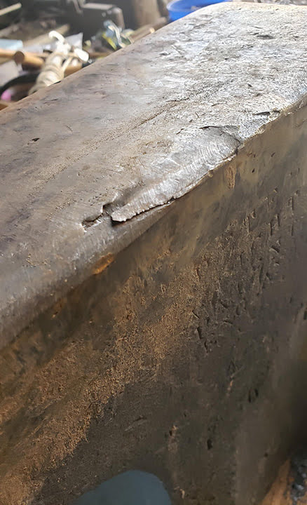
I really appreciate the advice from everyone. My biggest concern was doing more damage to it with that small edge sticking up. If the consensus is to leave it alone I'll take that advice. I may hand file the small 1/4" edge that's sticking up just enough so it's not a sliced finger waiting to happen. I'm also suspect of it's use as a mobile anvil (having moved it enough myself) but that's what my older friend told me he'd been told. Not really relevant now anyway since it'll be here for a long time. Out of curiosity, what was the average thickness of the hardened steel top on these? I appreciate your perspective Glenn, time has a funny way of turning oddities into beloved "features". Thanks!
-
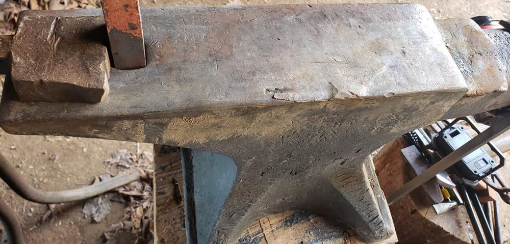
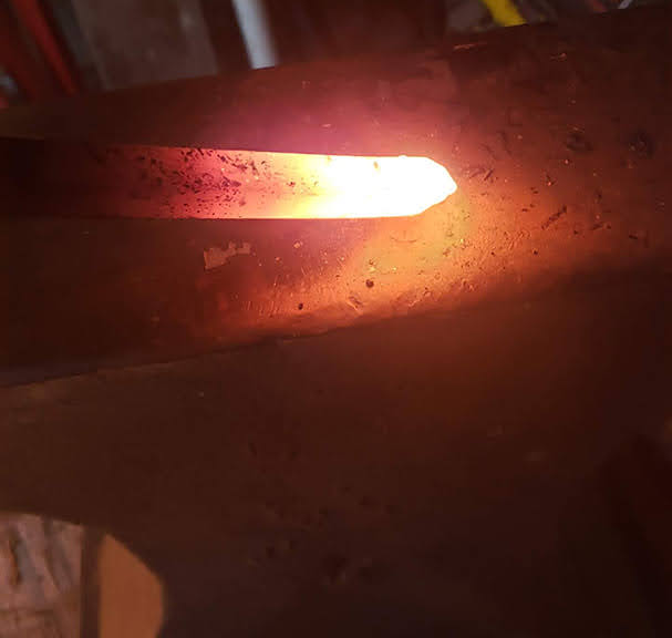
Hello folks, 1st time post here. I've read and done the research that many of you have recommended in other posts before I put this up here in the hopes of being as informed as possible before asking the community for assistance. Now I'm ready to ask for you advice or opinions. My son & I recently started collecting blacksmithing tools in hopes of making it a fun hobby for both of us. A good friend had this 1 3 1 (197lbs) Peter Wright anvil that he sold us for well under market price. Since the anvil was part of a Christmas surprise for our son, it was obtained & stored in wintertime cloudy & dark conditions (which is why I didn't notice this blemish until recently). The story behind this anvil is that it was used on a wagon as part of a mobile blacksmithing set in the late 1800's. From everything I can tell, this damage was here but kind of covered in a light patina before we started working on it. In one of the pictures below you can see the hint of the damage in the background as it's lit by the incandescent 1/2" bar stock in front. So, fast-forward to now and we're the new proud owners. It's absolutely usable by working around this one side of the work surface but my OCD (I'm an architect by trade so let the good-natured ribbing begin) would like to do something at a minimum to prevent further damage or preferably repair this spot. I've read and re-read the Rob Gunther & Karl Schuler process for anvil repair including their later amendment to change from Stoody rods to Messer rods. We're in Nashville in case there are any experienced anvil restorers in the area. Otherwise, based on these pictures, what would you seasoned pros recommend? I want to thank the group in advance here. I've spent hours reading posts & think this is an amazing community of truly helpful and genuinely interested craftsfolks. Thanks!