

Fowllife
-
Posts
165 -
Joined
-
Last visited
Content Type
Profiles
Forums
Articles
Gallery
Downloads
Events
Posts posted by Fowllife
-
-
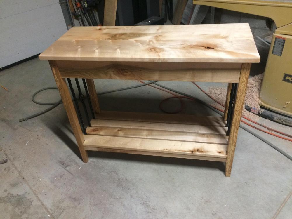
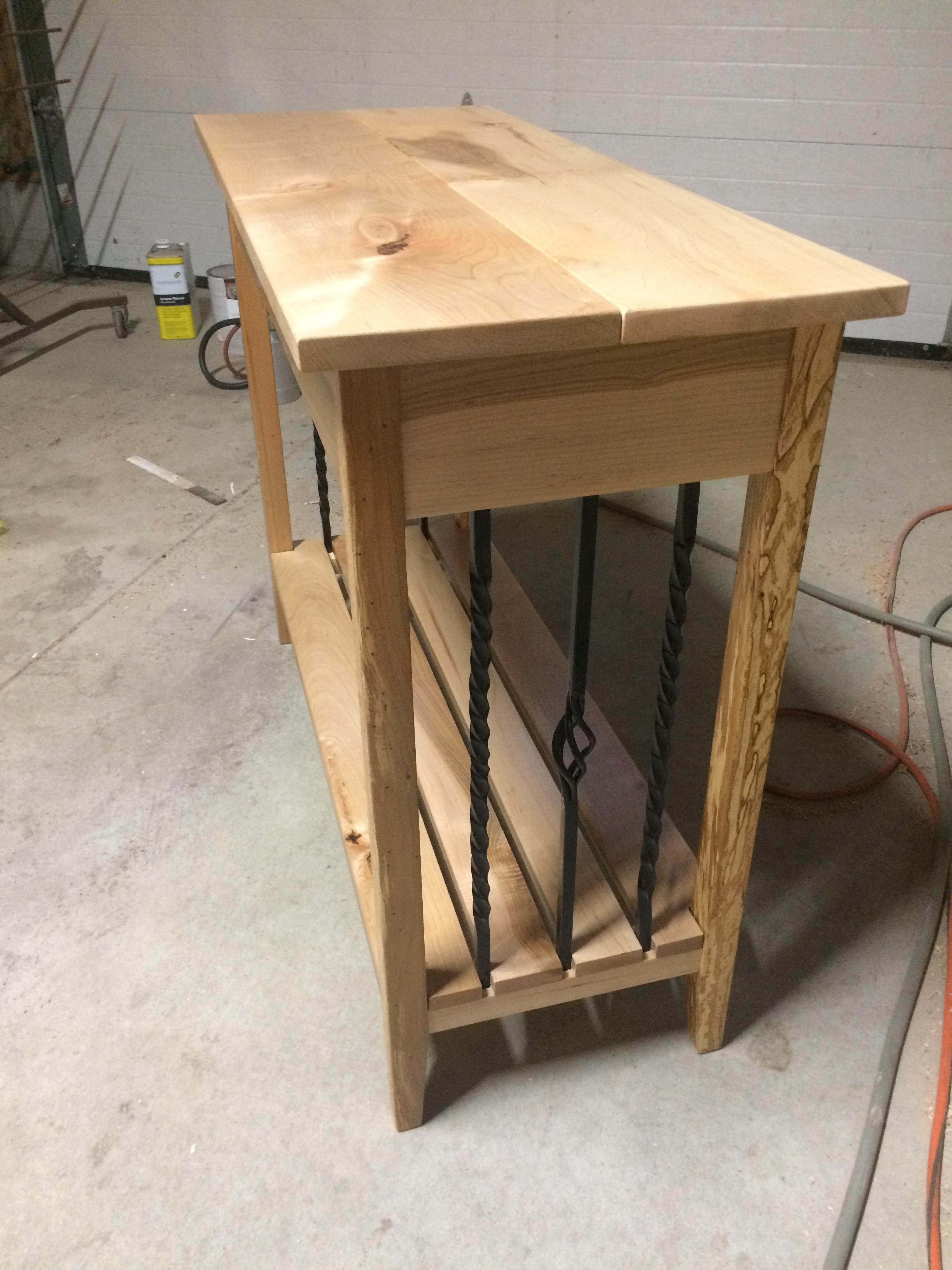
Not today, I have been working on this table the last couple weeks in my spare time. My wife requested another one and once again gave me the artistic license to do what I wanted in terms of style. I have an idea in mind, so since I woke up early this morning I started on a couple bending forks before making breakfast.

-
I made my own last year when I put an addition into the barn. I used the Simpson Strong-Tie LCB/CB style of anchor as a guide. If I remember right I used 1/8" plate at about 4' long each. I was using 6x6 post so the plate was either 4" or 5" wide, you would want to use 3" wide for 4x4 post. I bent them into shape and them welded a piece of 1/4" in for the intermediate base.
I'm not really a fan of the concealed connectors that Charles mentioned, like the Simpson CPTZ style connectors. I feel the U style provide a lot more support.
Another thing to keep in mind, the manufactured connectors will be galvanized, the ones you make will not be.
-
On a similar not, check the speed rating on the disc's you are using. I learned that lesson about 15 years ago when I bought my hand held gas cut off saw. I grabbed a new 14" blade from somewhere and never though twice. Within the first 3 minutes of using it to cut a house trailer in half the blade exploded, cut a heavy duty fiberglass ladder in half, and then went through the opposite side of the trailer.....stationary abrasive saw blades are rated for a few hundred RPM's less then what a hand held gas saw will spin.....luckily it only cost me a $120 ladder
-
On 9/30/2019 at 5:26 PM, Ben Hoover said:
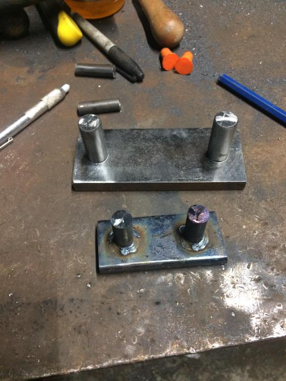
I know not to mess with the tool dies, I am going to use them as a poor man's swage for the moment. I THINK the quarter by half inch steel he gave me (about fifteen to twenty foot long sticks of it) are tool steel.
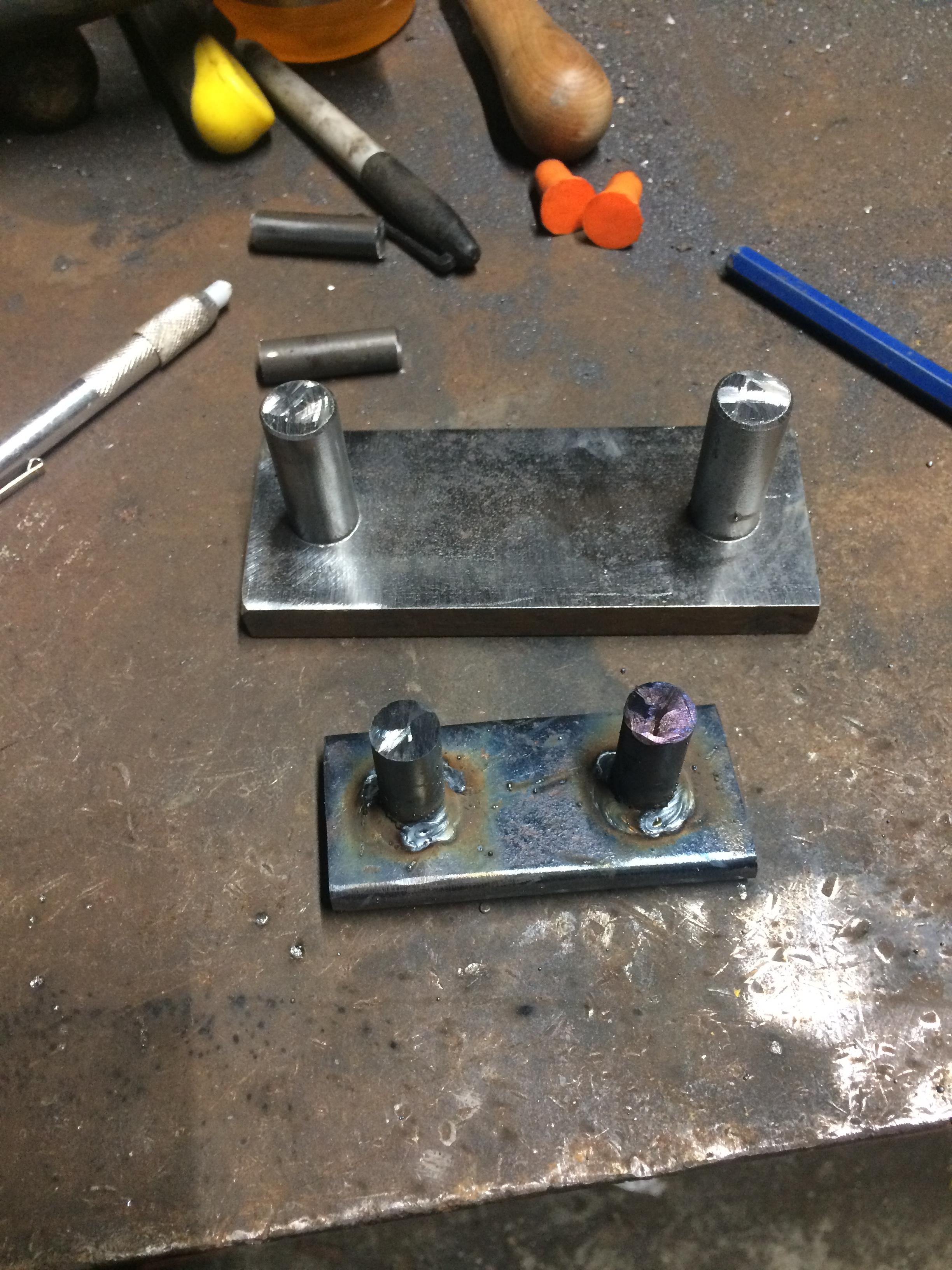
But those pins? I have not a single clue what they are. Any ideas?
I agree that the studs are Nelson studs. I'm not say they are not galvanized, but I would be surprised if they were since they are usually welded to structural members.
It looks like some of the other stuff is shim packs and weld backers bar. Depending on the type of connection they sometime send loose material to fill gaps for either a snug fit or to make it easier to field weld. I would also say the are probably A36 and not higher carbon steel.
-
If your doing a one of piece that takes you 10 months to finish, working full time, the only way to handle that would be time and material.....or a very large bid amount. Lucky for me I'm not that good at anything I do to have to worry about a project like that.....well, I have had projects take that long, but it was just stuff for my wife.....and I get distracted easily...
Latticino - You Sir are correct, there are some firms that do a lump sum contract instead of a percentage, Working for a D/B contractor we do very little plan and spec work, so I'm just more familiar with how some of the locals we work with usually contract. You are also right, I would much rather work on a large hotel then a large renovation. Luckily we don't do much design work for hospital renovations since more of them are plan and spec/ competitive bid.....I take it you're not a fan of VE.....I wont say any more......Thanks for mentioning "Hammer's Blow" I will make sure I check it out.
Anvil - I compare construction to blacksmithing because I am more familiar with it. In some ways they are very similar as they are a business that needs to be ran in a way that will make a profit. In other ways they are vastly different. We will do projects on a time and material not to exceed basis, we will also charge a design fee on certain projects, we will roll design cost into our bid, or even eat the design cost of we need the labor. The key is everyone needs to find what works best for their area, how they work, the projects they do, and the clients they work for.
-
On 9/25/2019 at 8:42 PM, Daswulf said:
An old lincoln tombstone stick welder followed me home today.
I know this has been discussed in length, but I believe I have the same pair of welders as you so I though I would give my input. I have a Hobart 140 along with the same stick welder. I use my MIG for 95% of what I do. The only time I really used the stick is for welding my just rusty equipment back together (6011 rod) or for heavy or structural welds. I wouldn't bother buying any 3/32 rods, as you will be able to MIG what these will do. I would stick with 1/8" unless you plan on welding 1/2"-3/4" material then 5/32" can be easier at times. 6011 is a deep penetrating rod good for dirty or rusty steel, and it not the easiest rod to use. 7018 AC would be ab easy rod to learn to use. I have noticed the Hobart brand rods I have seen at the farm stores have the amperage range printed on the end of the tube which will help you to start. I'm sure there are charts somewhere as well.
-
This topic is fairly timely for me and has a lot of great info. I have always seen things in straight lines. In art class in high school my teacher made us do a sketch every week, mine were always barns, houses, and buildings & done with a pencil and straight edge. I was told weekly to step outside the box and try something else, but I just couldn't make anything else flow. Last night when I was struggling to make a small scroll for an accent on a table I'm making that thought came back into my head. Thanks for the reference material, it was perfectly timed.
On the topic of design time, and charging for it. I work with CAD all day, and then do house plans from time to time after work, along with building cabinets and custom furniture. I never charge for design work for a cabinet or millwork project, it is just added into the estimate/bill. If I can't add the 5-20 hours of design into the price I think real hard if I should be pursuing the prospect. For house design I am being paid just for the design work, and nothing else. I have went to a minimum charge plus $xx/hr. In the commercial construction world design is charged mainly in two different ways. A design/build contractor will almost always have the design cost rolled into their price, so the owner doesn't see a separate design fee. Even on $5-10+ million dollar projects their is USUALLY not a design fee. Going the plan and spec route were an architectural or engineering firm is hired to do complete design, they would charge a percentage of construction cost.
-
The numbers I plug in for insulation value are actually the U-value for a tested system by an insulation manufacturer for the building type and application in use. Some of the variables are in which energy codes is used and the year of release.
As for overhead doors, there are some really nice commercial doors available right now with some great U and R values and some more effective weather stripping. I would have to look through my notes when I get back to work to give you some more specs.
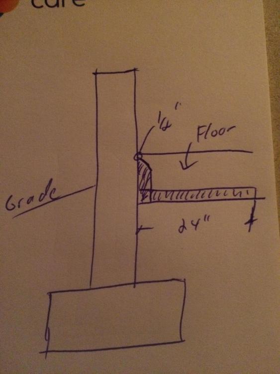
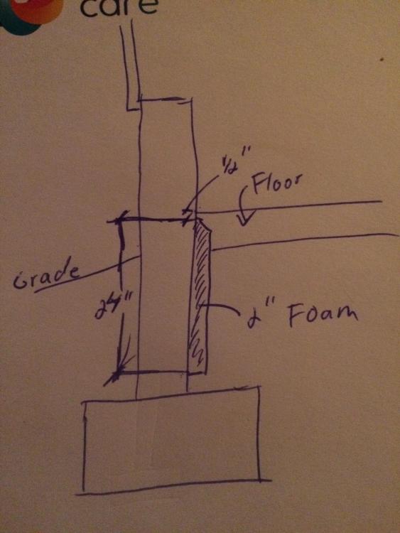
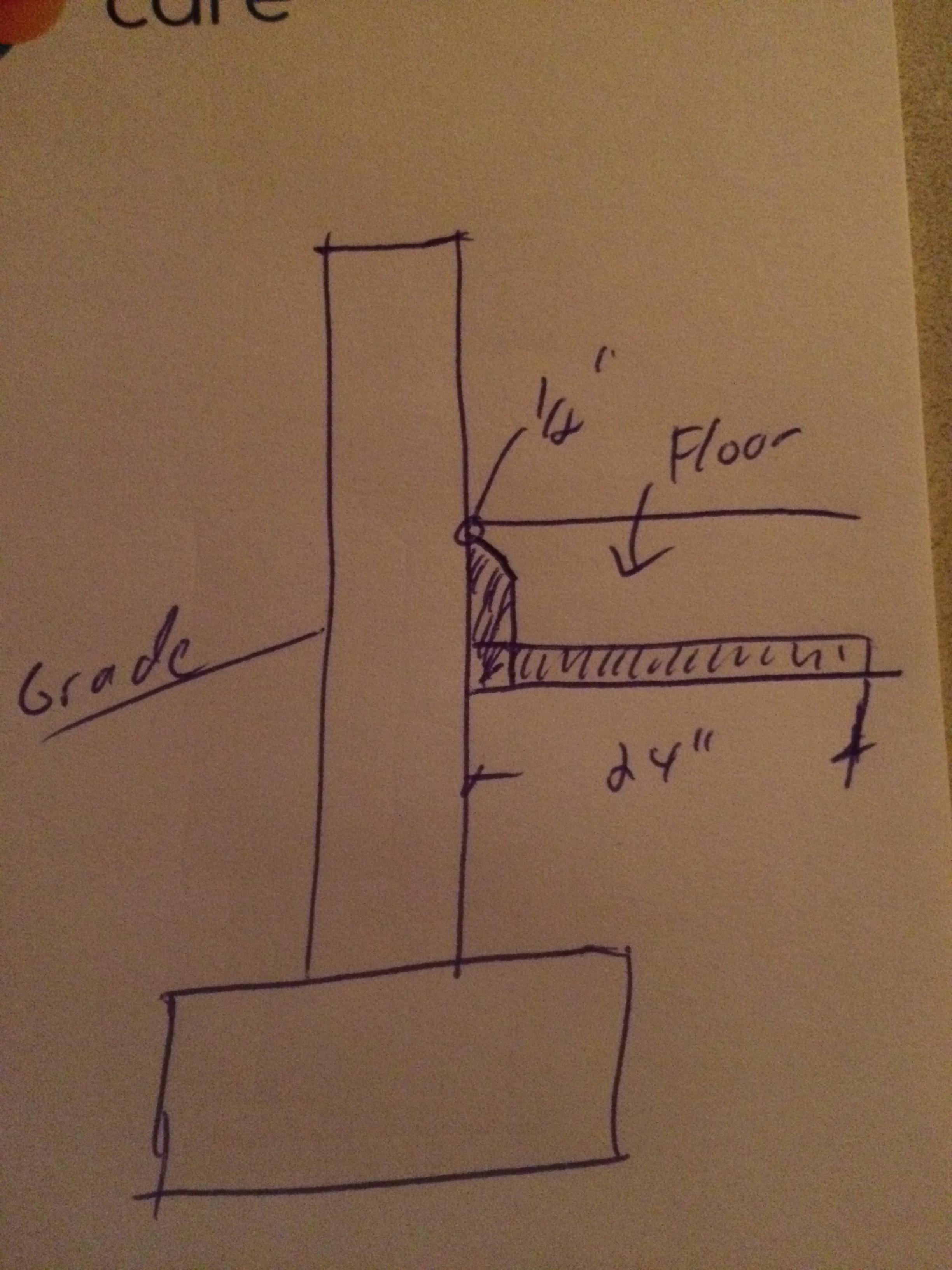
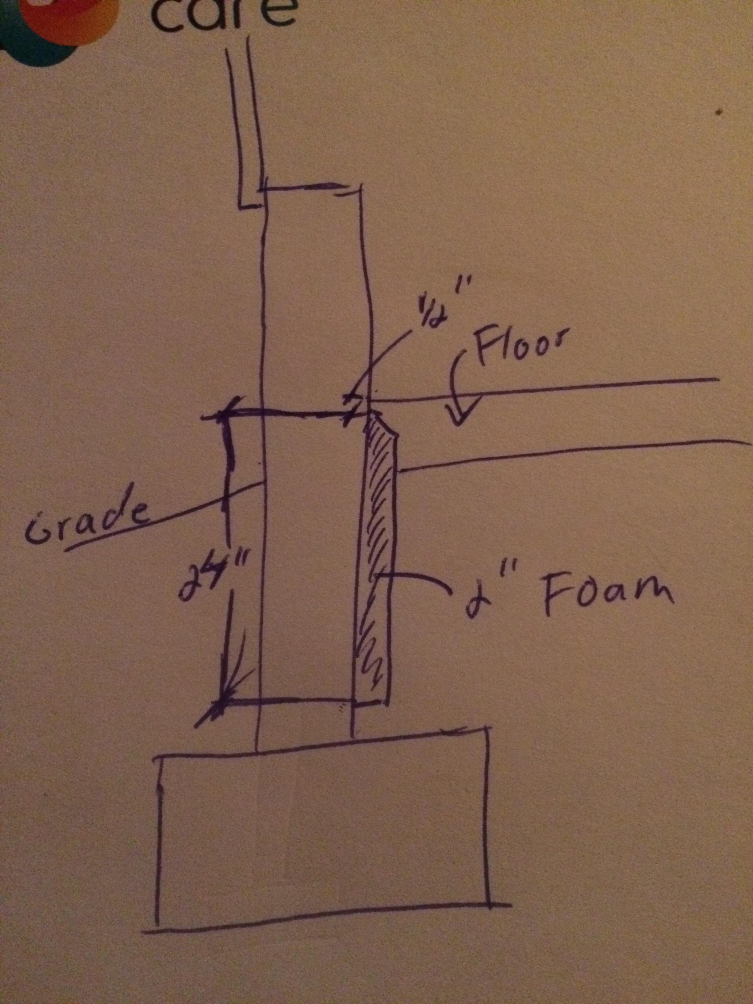
Vertically is how I would have done the insulation, I just wasn’t sure if you had enough depth to get 2’ bellow finish floor. The main key with the chamfer is being able to run the insulation as close as you can to finish floor without causing a week spot at the edge. Breaking the thermal short circuit between the floor and the wall will reduce the amount of heat transfer.
-
I did get a chance to run an envelope Comcheck on our building tonight. I had to make some guesses on a couple of things and just used the standard values for windows and doors. Running it with 6" in the roof and 4" in the walls it only "failed" by 4%. To get it to pass i needed either 8" in the roof & 5" in the walls, or 2 layers of 6" om the roof and 4" in the walls. I actually needed more insulation to "pass" in my location then you needed in yours, which surprised me a little. There are varuables with this program, but that gives you an idea. Using 6" in the roof and 4" in the walls would give you a decent envelope, but more is always better if you can swing it.
I’m not quite sure what your asking about the insulation. Attached is a rough sketch of what’s done in this area. Hopefully my rough sketches make sense.
-
R-10 should be 2” which is good. I prefer running it vertically on the inside of the foundation wall from 1/2” below finish floor down 2’ with a 45 chamfer on the top edge.
As for roof and wall insulation, there are variables. How do you plan on heating it, and what is your ideal working temperature? The usual answer is as much insulation as you can afford. With a pre-engineered metal building like you are putting up the insulation is typically installed between the secondary framing members and the siding and roofing panels. There are different options in how you can order the building that will affect What your options would be now. In my area it used to be typical to use 4” in the walls and 6” in the roof. With the energy mandates in the current commercial building code those numbers don’t work any more though. It seems like 2 layers of 6” in the roof and 5” in the walls is more typical now. I’m assuming you have a screw down roof, we don’t use that type of roof so I’m note sure what would work for that until I do a little research.
If I get a chance tomorrow I can try to run your building through the Comcheck program and get an idea of what would work in your area.
-
My comments were based on the assumption that there would already be some kind of mechanical ventilation. Building design is what I do for a living, and I just happened to be working on a mechanical plan for a warehouse that day so louvers and fans were fresh in my mind. I sometimes forget to turn the switch from commercial to more home/private type construction. I'm well aware of thermal loss from different sources. A lot of times insulation type, thickness, and how it's installed can cause more heat loss then openings. On the commercial level we have to design everything to comply with the energy code for building envelope. You would be amazed at how much the details can affect compliance. If I remember right building code requires 0.5 air changes per hour but we design almost all of our buildings for 1. Oversizing fans and adding a VFD would let you dial in the air change depending on need. Like I said, my mind gets stuck on building code stuff and I'm just babbling now.
But, I digress. Point of use systems are not a bad thing, it just takes a lot of planning if your going to put them in the floor since after it's in your not moving it. If in the floor is what you would prefer that is fine, it's just not very common in a commercial application.
-
On 8/5/2019 at 1:19 PM, jlpservicesinc said:
Frosty sorry if my PM sounded stupid but maybe now you can see why I asked about how you laid out the vent pipes in the floor.
What kind of vacuum pump or blower were you thinking?I'm out of the loop with what you are talking about here, but if you have a high water table I would avoid anything exhaust piping in the floors.
I'm assuming you are putting some exhaust fans and wall louvers in? If so just up size them for 2 or 3 air changes per hour and forget the floor vents. Install the exhaust fans on the same side as the welding/fab area and the louvers on the opposite wall. Have the exhaust fans on a VFD interlocked to the louvers, much simpler and easier system. Maybe it's a regional thing, but of all the fab shops I've either been in or worked on design, non have floor vents. The only time we seem to see those is auto or truck repair shops and most owners would prefer to see them ceiling mounted instead of in the floor.
-
Thanks Guys
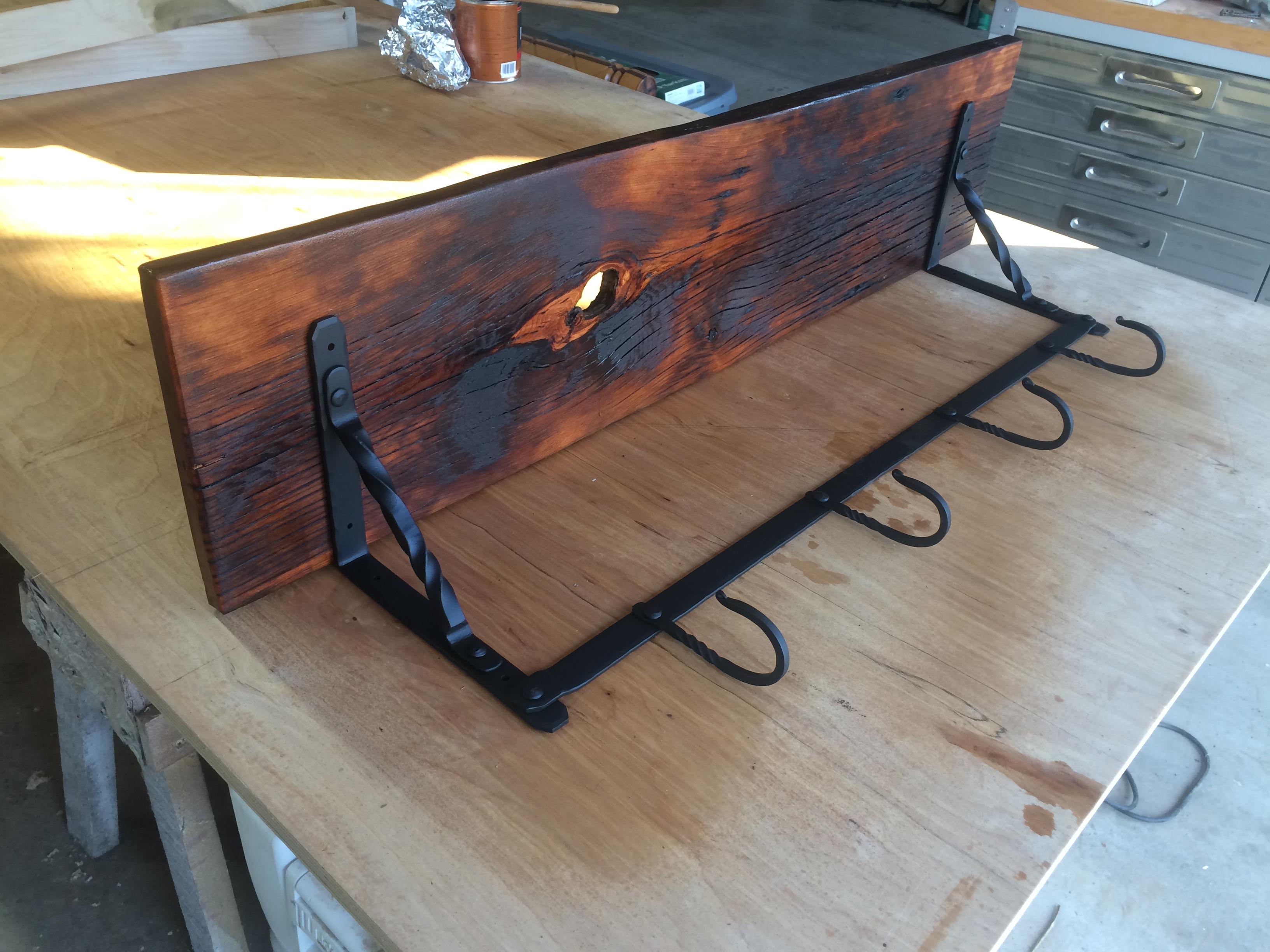
Jim, thanks for the suggestion. I was more thinking decorative instead of functional I guess. The bottom bar is only 3/16x1” so I wasn’t envisioning I lot of weight on it. I would have like to round out the rest of the hook after the twist and do a better taper, but time wasn’t on my side.
-
Not really today, but the last few days after work. My wife has a fund raiser at work and I volunteered to make something to donate. First time for me using rivets to hold it all together.

-
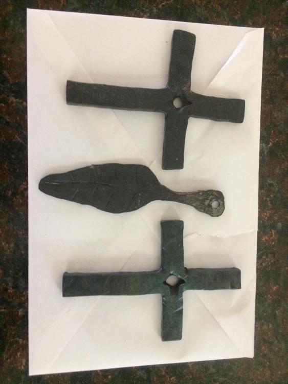
Our son is home on leave and wanted to give working some hot steel a try. He made a pair of split crosses and a “leaf”. I think he plans on attaching some cord and giving them to his grandma before he goes back. It was nice to teach him a little of what I have learned over the last few months.
-
A quick check shows that a stock MTD log splitter has a cycle time of 19 seconds with a 25” stroke, or 2.6”/second average. I suspect older units are slower. The one I referenced earlier would be around 3.3”/second. If yours is 4”/second it would do a complete 25” cycle in 12.5 seconds. That’s quite a bit faster then the average log splitter.
As for the detend valve, both of the ones I use are a 3 position valve, extend, retract, and home. There is no reason that type of valve would not work for a press. I have not personally used a splitter that would automatically retract without being able to stop mid cycle.
-
I find it odd you have a 30a outlet on a 60a breaker. It’s not a good thing to have an outlet with an over rated breaker, although your dryer won’t use more then 30a.
i love to spend other people’s money, but have you thought about using your spare 60a breaker from the basement and putting a sub panel in the garage?
You could also just use that breaker to run a new outlet to the garage, which would solve your 220v issue.
-
Just like anything else, it depends on what you start with and what you expect in the end. If it has a big enough 2 stage pump it could be plenty fast. Both of the splitters I use make a complete 20" or 24" stroke cycle in around 15 seconds. Mind you those these were both custom build, I have never used a factory built splitter to know how fast they are. I also have never tried to use one as a forging press.
-
Frosty brings up a good point about draw from a 3 hp motor. Someone smarter then me can correct me, but I believe the full load drawn from a true 3 hp motor on 115v is over 20 amps. If I remember right a true 3 hp motor on 110-120v should have a 30 amps breaker? I know I used to have a "3 hp" air compressor and I had to be careful where I plugged it in. I could not use and extension cord, and it would pop breakers pretty easy plugged directly into a 20a outlet.
It may work for you, but I would look at circuit length, wire type, and breaker size before you get too carried away with buying a motor. There is a reason "most" motors 2 hp and under are 110-120v and "most" 3 hp and over are 220-240v.
-
Looking at the picture of your current motor to pump connection, I would try to straighten your pump mounting plate if you can. That's a love joy connection, typically the rubber cushion doesn't last very long if they are not lined up.
I was wonder how your setup would work with the slow speed. Seeing that you aren't overly impressed makes me second guess trying to use my 2 hp motor for a press. It almost seems like you need at least a 3 hp motor to et decent speed and power, but a 5 hp is better. It seems like the route Peppie went is the best, 5hp motor with a 2 stage pump. I have not looked, but I wonder if you could fine a 2 stage pump with low enough flow rates to work with your 1 1/2 hp motor?
-
14 hours ago, JHCC said:
I did just spot a small hydraulic pump at the industrial surplus place that (according to the manufacturer's website) does 2 gpm at 1,200 rpm and 2.5 gmp at 1,500 rpm; I deduce that it does about 3.6 at my motor's 1725 rmp, which is well within its maximum speed of 4,500 rpm. The maximum psi is 2,500, which would give about 15.7 tons of force.
If we us the formula HP = flow x pressure / 1714 that pump would take a 5 HP motor (3.6x2500/1714=5.25hp). If you run the numbers backwards I think the best you could do with your 1.5 hp motor would be 1gpm @ 2500 psi.....Going to a 1gpm pump would speed up your stroke by about 30% but would reduce your force to about 15tn going to 2500 psi.....if my numbers are right.
-
I would say you definitely want to use a nut at the cylinder cap so you can torque to the proper spec, and then attach to the table top. I would also think lock tight would be a good idea on both the nuts holding the cylinder together. Maybe your contact at Parker can help you with that, and a torque spec.
Frosty - I would agree with in regards to big box quality all thread. I would absolutely not trust that in this application.
-
In tension I would agree with that, a bolt is only as strong as its weakest point. In shear it’s a different story.
By heavy do you mean longer/taller, or thicker? A long nut would give you more surface area and wouldn’t hurt at all if you can make it work.
-
I have the bites & drills that would make your job easier
So, how many guys plumb in pressure gauges to see what operating pressure they are running at? Seems like a no brainer for pressing out bearings and such, or for cold steel work. Maybe it’s not a big deal for hot work?


Anyone need help?
in The Business Side of Blacksmithing
Posted
Are you a member of the WRABA (Western Reserve Artisan Blacksmith Association) or the NOB (Northwest Ohio Blacksmiths) Both of these groups would be much closer then SOFA for you and may be able to give you some guidance. Maybe get a hold of Cleveland Blacksmithing and see if they could use any more instructors?
I would start by joining the WRABA if you haven't already and go from there.