
Another FrankenBurner
-
Posts
625 -
Joined
-
Last visited
Content Type
Profiles
Forums
Articles
Gallery
Downloads
Events
Posts posted by Another FrankenBurner
-
-
Yeah, I too am guilty of spending too much time on burners/forges and too little on the fruits of that labor.
-
8 hours ago, Mikey98118 said:
It was short for flame retention nozzle
When I write the term nozzle, your "flame retention nozzle" is implied. At least in my head, which others don't have access to. I suppose I should write it out in full as well so that there is less possibility for confusion.
8 hours ago, D.Rotblatt said:I don't know if the pressure in the plenum is comparable to venturi theory.
I was more so meaning that the connecting tube which you are sliding the burner in and out of is responsible for the pressure changes. I am with you on the plenum being it's own monster as far as variables and what is happening to the stream once it exits the connecting tube into the plenum. I have a mental picture of what may be happening in there but it is speculation at best.
8 hours ago, D.Rotblatt said:It may be more sensitive to nozzle length being that it's flowing into a box rather then into the open air or a forge.
It doesn't sound like it. My burners can go from lean to rich by changing the nozzle overhang alone. I am not sure if it is changing induction dramatically or if the fuel/air ratio has a small range of happy.
8 hours ago, D.Rotblatt said:so I may have to make a new one that has a larger opening on it that can take different sized tubes.
More speculation, I wonder if you made dramatic changes here, if the burner wouldn't like it. To the point that you may need to increase/decrease the quantity of ports. Mikey's stepped flame retention nozzles are stepped to make a more dramatic expansion to slow down his high velocity FAM stream. To put on the brakes as he puts it. Your port quantity is balanced to your stream velocity and volume. If you slow it down too much, maybe you get to flashback territory. I am not sure how picky the NARB's are with this. Especially yours since it seems to be below the quench distance. I should probably get off my butt and start playing with ribbon burners a bit deeper.
9 hours ago, pnut said:How do you think the forge would hold up outside covered by a plastic tote or box of some sort when not in use.
I once had my forge directly rained on for quite a while, which upset me greatly. I started it in bypass flame for a nice low heat. After the steam stopped billowing out and the forge got to a low red, I turned up the heat and all was good.
Somewhere I read that the refractory is hygroscopic. If this is true, you heat the forge regularly which keeps it bone dry and when you shut it off, it absorbs moisture from it's surroundings. I have no idea if it's true but I start my forge with full heat and have not had any problems. If my forge has been off for weeks, I give it a few minutes in bypass before I kick on full heat. Not sure if it is needed but it only costs me a few minutes.
-
On 10/13/2019 at 11:44 PM, pnut said:
So it's more a matter of justifying the expense and finding time.
I understand. If you are looking to justify the build, one thing I can say is about the time savings. I like both solid fuel and gas forges. In terms of not having much time but wanting to smite some steel, the gas forge is a time saver. I can forge more often because of the simplicity and ease of the gas forge. It's an unfair comparison but liken it to cooking dinner over a camp fire vs a gas stove. No time spent building or managing the fire, no clinkers, no shoveling fuel, no smoke. Light it, let it preheat, do your work, shut it down. I have done it several times in one day.
On 10/14/2019 at 9:29 AM, D.Rotblatt said:Latest cast burner. Works great.
And it looks good. Nice job.
As to the step flare talk, I like the term nozzle which I think I picked up from Mike's book. Flare makes me picture an expanding taper on the end of a cylinder. Like bell bottoms, the flare with flair. Now we have 3D printer nozzles to add to the confusion.
I suspect you are tinkering with plenum pressure. The definition of Venturi effect that I find most often is a decrease in fluid pressure as a result of passing through a constricted section. This would apply to any burner using a reducer as the inlet and it is part of why so many use a reducer. The outlet taper from the throat of a Venturi tube is for the opposite effect, pressure recovery. Converge to drop pressure and diverge to recover as much as possible. This is where the 1:12 angle comes from, it is the fastest expansion possible that does not cause turbulence which would hinder this recovery. While you are stepping, which is a faster expansion, it is still better than the huge immediate expansion at the plenum. More plenum pressure, more push, more induction. Leaning out the flames a bit.
This is what I suspect but I could easily see the opposite being true instead. Your flames being too lean, you increase nozzle length, which increases drag and decreases induction.
Either way, as Frosty stated, it is a final tuning by making small changes to the fuel/air ratio. One reason Mikey controls the overhang on his sliding stepped nozzles.
-
Thank you. I originally started this thread to list my feats and failures in the hopes that some could learn from it and others could educate me. I have been educated, inspired, encouraged, and motivated here.
I am still tinkering. It has slowed as I am studying for an exam for work. After reading code for several hours a day, my mind is too melted to think burners. Hopefully I will be done with that soon.
With the straight burners, I have not improved beyond v46. Lots of experiments(up to v80) but not a lot of change. I am playing with inlet shape in the hopes of reducing the size of the inspirator. I have also been playing with straight ribs to eliminate the helix vanes. They reduce air induction some and they require investment casting, at least so far. They are doing something special though, I can't seem to get away from them.
I am also playing with 3/4" burners. I don't see myself using them for forges. These things put out way too much heat. We are using one in the foundry furnace. I like smaller forges though. We have a 450 in3 forge running two 1/2" burners and it seems like a cavern. The 185 in3 forge demands much less fuel and accommodates most of the things we are doing over here.
On 10/11/2019 at 6:40 AM, pnut said:take the plunge
I interpreted this as meaning that building a forge is a monumental task. If it is correct and it is causing hesitation, I did the same on my first one. Once I got started, it finished quickly, I wondered what all the fuss was about and moved on to thinking about the next forge. I hesitated longer than it took to build the forge. Plot what you want and get started. Building a forge the easy part.
-
It is possible. I took a 3/4"(0.824" actual ID) burner which used a mig tip and increased it's performance by going to a 3D printer nozzle.
If you are over it and just want to forge, try your burner as is. Post pictures of the flame in the forge and we can try to help tune it the best it can be.
If you need/want to go to new build, try a recipe burner. The easiest is the Frosty T. This will reduce the tinkering required so you can get to smiting your metal.
If you are playing with a gas forge, learning to interpret flame is helpful. The difference between a tuned burner and an out of tune burner can be dramatic. A difference in forge/flame temperature, dragons breath, fuel consumption and carbon monoxide production.
-
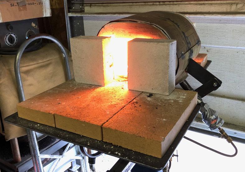
We made a 4x4x2" mold which we line the bottom and sides with 1/2" of Kast o Lite, we pushed a piece of rigidized ceramic wool into the middle, and cap the top with 1/2" of the refractory. They have held up well as our doors.
-
On 8/29/2019 at 11:49 AM, bertie_bassett said:
(yes it is a little crooked)
That last photo you posted, it may just be the photo but that orifice/jet looks very out of alignment. If so, that is a problem. Out of alignment, even a little, can cause major problems. If you can disconnect the burner from the fuel line and connect it to a water line, this will tell you immediately.
-
No need to apologise. Since there are no set terms, it is hard to talk about.
I understand now. One concern with doing that is that it would take away the ability for the orifice position to be adjusted. I like adjustability so that the burner can be tuned when it in it's final position. I suspect the best jet position may be different depending on the intended use (small forge, big forge, ribbon burner, hand torch).
Not that I don't think it wouldn't work. I think it would work just fine with the best average orifice position.
-
I am not quite following what you mean. Could you describe/define what you are meaning when you say injector tube and also nozzle.
I think by nozzle, you are meaning the fuel orifice/jet? By injecting tube, are you meaning a divergent outlet from the throat?
-
When you say 0.036-0.040 jet, are you meaning actual diameter? I thought you were running a 3/4" injector at 035-045 mig tips with your NARB.
-
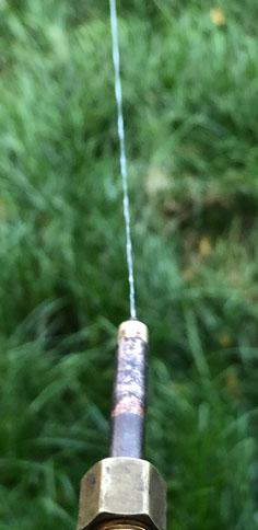
Now that I know the 1mm is measured running the forge hotter than the rest, I setup a burner in open air to take a good look at the flame. I also took a look at the same burner with the mig tips I was running previously to see if I noticed a difference.
Previously I had run this burner with the 030 mig tip. I forgot I had run it with the Miller 030 mig tip because it ran better than the generic. The Millier is at 0.037" and the generic is at 0.039".
With the 1mm(0.0394") printer nozzle, the flame is shorter and louder. It is exactly what Mikey describes as a neutral flame. A uniform light blue color.
-
That is the "small" forge which is at 185 in³. It has 1 inch of blanket and half inch of kast o lite. The next will have 2 inches of blanket, 3/8 inch of kast o lite and a coat of plistix 900F.
-
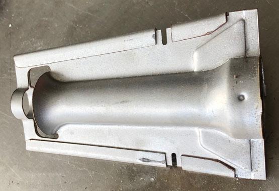
We are using these nozzles with a printed/cast inlet chamber. In the image of the forge, you can see it. Unless I am misunderstanding what you mean.
-
There is no dent or burr. I was excited about playing and made the connection too quickly/sloppy. The printer nozzle was brazed in at a small angle.
I am a full convert. 3D printer nozzles over the mig tips. Working with brass instead of copper is great. These induce more air per orifice diameter. I suspect they are putting out more fuel as well.
Thanks for the suggestion G-son.
We made up several new tips with the 0.4mm, 0.5mm, 0.6mm, 0.8mm, and 1mm 3D printer tips. We drilled out a few to 0.043", 0.046" and 0.052". We have quite an assortment to play with now.
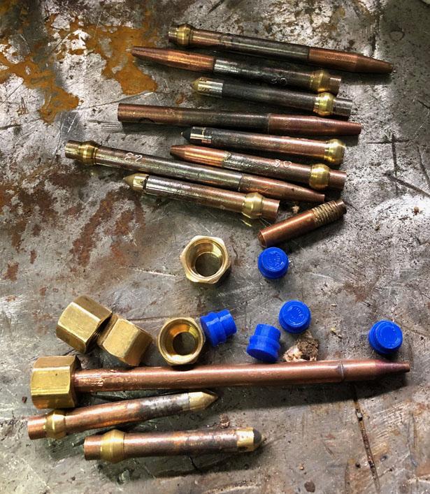
The 3/8" burner does well(in free air) with the 0.8mm and the 1mm. It will be interesting to see what it does in a forge. I suspect it will back down to the 0.8mm.
We ran the small forge for several hours while swapping out tips and leaving the pressure alone. It has the 1/2" burner which originally had an 030 mig tip. We tried the 0.8mm, 1mm, the drilled out 0.043" and 0.046". We listened to the sound, inspected the main flame, monitored the dragons breath, and did some temperature measuring.
The 1mm tip is hands down the winner. No dragons breath, violent loudest roar, 100°F higher forge temperature. At 5 psi we are running 2450°F in the forge.
It is interesting that the 1mm(0.0394") was the replacement for the 030 mig tip which measures at 0.039". On that thought, we drilled one out to 0.052" to match the 045 mig tip in the foundry 3/4" burner. This burner turned into a whole different dragon. We are looking forward to the next pour for a real test of performance.
I am now planning a 1/4" burner which uses these. Maybe a smaller burner, just because I have the tiny orifices to go with it.
-
We have been testing the 3D printer nozzles as jet orifices. I had one which performed much worse than expected. I connected it to water:
Hmm. We were a little quick with the assembly of this one. More care with alignment. Since I had the water rigged up, I checked several tips. Most of them were great. I had a generic mig tip which the tip itself was aligned but the jet veered off.
As to the printer nozzles as orifices, the 0.8 mm and the 023 mig tip are similar bore. When connected to water, the printer nozzle stream jets out twice as far as the comparable mig tip. When put into the 3/8" burner, the flame is shorter and has a roar. It looks very good. I like it.
I am going to try the 1 mm in the 1/2" burner next. I think I will have to drill out the 1 mm to larger sizes to find a good match for the 3/4" burner. You can get a few larger sizes but they are not common and the range of sizes falls off.
-
Brick House burner

-
I was meaning that the term naturally aspirated does not describe the shape of the burner tube. It simply means it does not have a powered air supply.
Mikey burners are a straight burner because they have no reducer. Reil burners are constricting. The inlet constricts to the mix tube.
Add the tapered outlet and you have what looks like a Venturi tube. They use the terms convergent section, throat, and divergent section when talking about Venturi tubes.
-
I had picked up on disdain for Venturi. Now I understand. Thank you for the information. It is disheartening that history is filled with so many examples of trading integrity for notoriety and a pay check.
At least you can't really know about Venturi without knowing about Bernoulli. To use a Venturi flow meter, you have to use Bernoulli's equation. Not every Bernoulli is a Venturi but every Venturi is a Bernoulli, kind of thing.
I think I understand what you are meaning with the mechanics. You are saying that the same dynamics which entrain air in a burner without a constriction(e.g. a Mikey) are also responsible for some of the air entrained in a constricting burner?
For nomenclature, Venturi burner is an industry term. So is naturally aspirated, which is interchangeable with atmospheric, but this describes any burner which isn't blown/gun/powered/forced air and is not a description of constricting burners vs straight burners. I recently found the term inspirator but it also describes the naturally aspirated device which could be constricting or not.
We can use the term waisted in lieu of Venturi, but it opens the door to "My burner is so waisted that it can't work."

-
I don't believe the curve has anything to do with the measurements of the pitot tube aside from preventing turbulence at the ports. The center port is pointed parallel and into with the fluid flow so it is being pressurized by both the static and dynamic pressure, the total pressure. The side ports are perpendicular to the fluid flow so they are pressurized only by the static pressure. The difference between the two measurements is the dynamic pressure. With these measurements, the Bernoulli equation can be solved for velocity. In a plane, you can determine your airspeed. In an HVAC duct, you can determine the air velocity which can be used to calculate air volume.
-
Great stuff happening in here.
I have done a bit of research on the Venturi effect and have found nothing except the decrease in pressure through a constriction stuff. One page stated it as "Increase in fluid speed results in decrease in internal pressure." One page listed airfoil lift as an example of the effect which did not fit the in a pipe narrative but it contained the same explanation and listed gas burners as one of it's other examples. Several of the pages with examples included inspirators(burners). Several of the pages list different jet pumps as examples of the effect. If researched, inductors, injectors, eductors, and ejectors all lead to several pages which state that they employ the Venturi effect. They appear to be using similar dynamics.
Unfortunately, I can not find a good source to explain what the Venturi effect is in any more detail. I found his writings converted to English but it is a deep dig.
If not for the lower pressure, what is the purpose of the constricted section in the griddle burner I posted above?
As to the pitot tube and Venturi, I don't understand. As far as I know, the pitot tube has nothing to do with the Venturi effect. The front port measures the total pressure which will be a higher pressure than the side ports static pressure unless there is no flow across the device. I thought the rounded front was to reduce drag. There are two tube versions which measure the stagnation pressure with a straight tube. The pitot tube and the venturi meter are two contrasting methods of flow measurement.
-
That is a long post, thank you. I will have to churn that for a day.
I have to respectfully disagree with the burners not using the Venturi effect. We are forcing fuel down a constricted pipe and using the resulting low pressure to draw in air.
7 hours ago, Frosty said:Too small a gap and the flame leans out, too large and the flame richens up and weakens.
This is interesting and I am quite curious about it. I am planning several experiments to understanding more about the basics.
-
The read somewhere that the measuring venturis typically have an inlet cone of 30° and an outlet cone of 5°(included angles) to reduce aerodynamic drag. This would give you a throat angle of 200° which isn't very sharp. That is provided the cones line up. These venturis have a different intention and a lot of them are used in applications where the stream being measured is moving in relation to the venturi.
Page 17 of the 3D printing thread, member BriJasher links a couple of videos talking about the purpose of a trumpet/bell shaped inlet for turbine engines on a test stand. It deals with efficiently inducing non moving air into an object with a static position.
-
23 hours ago, D.Rotblatt said:
I was amazed that just because of this I was limiting myself to a preset tube size
Yes, but it's fun. It's kind of the blacksmith burner way. Trying to squeeze as much down the pipe as possible. More btu's without staying within those confines is easy.
We are reinventing the wheel back to the venturi burner but it isn't a fair fight. Venturi burners are almost the only NA burners I see commercially. I have been experimenting, trying to increase my understanding of the inner happenings. I originally thought the outlet taper was about reduced downstream drag and vortex geometry but the more important thing happening is the increase in static pressure of the FAM at the delivery point.
Now I am trying to determine how changing the inlet reducer shape, throat diameter, and outlet taper length changes the static pressure, what the limits are(and why), and what this does to the flame. As Frosty stated, it's an endless journey.
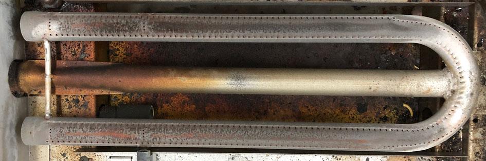
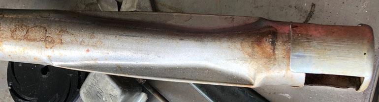
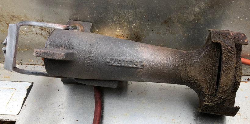
I took a handful of pictures of some of the commercial burners I have seen recently . These are all low pressure, relatively large orifices, and low temperature application.
This guy is one of 20 burners which were in a large HVAC unit.
This one is out of a large griddle top. The orifice is behind the wall on the left size which feeds into the venturi under the cross bar.
Here is a shot of that venturi, after I cut the burner apart.
This big cast guy is for a pizza oven. IIRC he is 170,000 btu/hr. He is a blown burner.
I thought this one was neat. It is the only one that I have seen like it. It was on an old condemned HVAC.
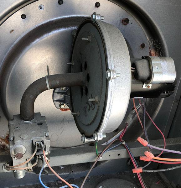
On the lower left you see the gas valve which is plumbed right into the blower housing. The orifice discharges into the blower suction and the blower mixes the FAM as it is delivered.
-
Question for Frosty, do you happen to know what that final pipe size is in the forge you posted?
Thanks for the information Billy. Are your water cooled NARBs something you are keeping close to the vest or are you willing to entertain the curious?
4 hours ago, D.Rotblatt said:is this then a 1" burner, or a 3/4" burner?
As Mikey stated, your mix tube is mostly 1 inch pipe. I suspect this burner will need a larger jet, probably a bit larger.
Full length tapered mix tubes can not be categorized into the same size categories. The commercial burners I deal with are all rated in output capacity(btu/hr). Not so easy to determine in your garage. If you are using mig tips, you could compare to pipe burners which use the same tip at similar pressures.
I am playing with similar. The small tapered tube we cast is an adapter for half inch heads to a 3/4" mix tube. I am able to go to the 045 tip in this burner. I also have a straight 3/4" head(No tapered outlet from throat or spiral vanes) which induces similar air using the same jet. I am now trying to figure out if there is much of a difference in performance(possibly in different applications), how so, and hopefully why.
I look forward to your results.
3D printed plastic burner experiments (photo heavy)
in Gas Forges
Posted
I should have stated that differently. What I meant was that I am guilty of not balancing my time well. I fully intend on spending much more time on burners. I just have to fit forging in. For me, forging is therapeutic. If I start to get grouchy and life seems to not make sense, I need time at the anvil. Then all is well again. At least it's a manly binky.