
Another FrankenBurner
-
Posts
619 -
Joined
-
Last visited
Content Type
Profiles
Forums
Articles
Gallery
Downloads
Events
Posts posted by Another FrankenBurner
-
-
In my case, I used an oversized piece of PVC pipe. I went with dimensions that closely match Mikey's stepped nozzle which left a tolerance between the mix tube and the kastolite. I varied the depth of the mix tube into the nozzle area (control over hang) but it didn't seem to make much difference, maybe because of the tolerance. It stays lit and I have been checking the mix tube for oxidation. So far so good but it hasn't been used much yet.
I believe it was in Forges 101, someone talked about turning a wooden plug with a taper to ram a tapered nozzle in the kastolite. I'm not sure if that would be a better idea.
I am also going to play with partially blocking the area between the burner mix tube and the burner mount tube to vary the amount of secondary air that might be drawn in to see if it changes anything within the forge.
-
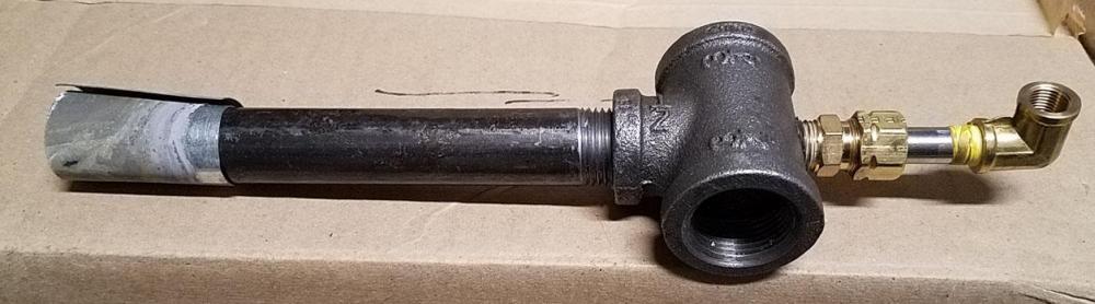
Howling dog forge: I used a lathe to drill and tap the Tee which made easy work of it.
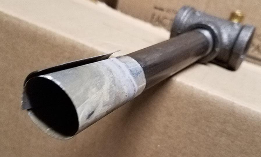
The flare in the images was a very temporary (read impatient) nozzle to see it running. I cast the outlet nozzle in the kastolite hot face so I don't have a metal nozzle at all.
As to mix tube length, Mikey has information in burners 101 about that. IIRC, longer softens but lengthens the flame, shorter gives a shorter bushier faster flame. He recommended longer for hand torch type use and shorter if trying to prevent impingement on your work. But for general forge use, it's sounds like a happy middle ground. I was happy with the burner at 4 1/2 inches.
-
Yes sir, I think what you are describing is correct. The further back away from the mix tube, the more air is induced. I see shades of green in your flame photo, definitely need more air. How does it run with the jet threaded as far back as it can be?
I measured my burner mix tube and it is 4 1/2" as well. I use the .023 mig tip and it will stay lit through a good range of pressure, outside of a forge, with a very crudely rolled tapered nozzle. They do work. Though I seem to recall that these burners don't do particularly well without the back pressure created by the forge.
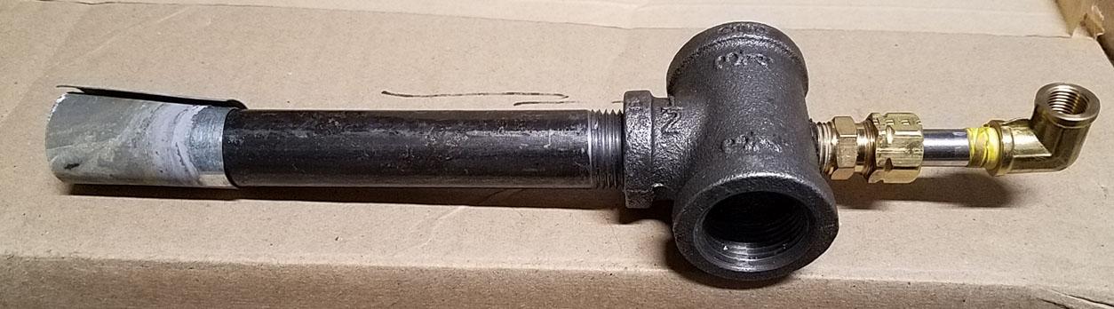
I don't have my burner connected so I can't show any flame photos right now but here are a few of the burner if it helps any.
-
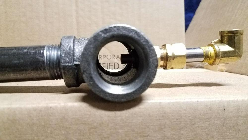
You said you drilled new jets. Can you get a good picture of your fuel fitting assembly including the jet? Is the jet's position adjustable within the Tee?
-
According to Ron Reil's website, the .023 mig tip has an actual orifice of .031" and the .030 mig tip you are currently using has an actual orifice of .038". I have built the 1/2 Frosty T burner using the same T and length of mix tube. Even the .025 tip ran a little rich for me so I installed the .023 mig tip and it does better. It turned out to be a nice burner.
-
I had not thought of that, with the NARBs. They are an orifice of a given size at a given pressure. Do you feel that the NARB you are using is equivalent to what would be the matching tube burner? At least in terms of heating the same volume of forge to similar temperatures. Do you suspect a 3/4 inch NARB would follow the 300-350 cu. in. general suggestion?
-
It seems like the burner block itself would determine the minimum and maximum through put of the air/fuel volume and the rest would be adjusted to be within that range. In the case of Frosty's NARB, he had to design the burner block to match the available air/fuel volume at the low pressures. Where as the blown version that Wayne Coe has on his site has a bit more nozzellette area but the blower and fuel can be increased to match it.
A lot of the ribbon burner builds I see, don't use a fuel gas jet but a needle valve. With no way to quantify fuel input, the ability to pump in air and increase fuel, different input plumbing, different blowers, and different burner blocks with different quantities and sizes of nozzellettes (Frosty's term), wouldn't that make the ribbon burner output too variable per burner to make a general suggestion?
This post is meant to be a question for those who know more then I do. None of this post should be read as fact.
-
Thank you Mikey and Frosty. I will purchase the Plistix because of it's higher melting temperature for the current forge. I will also be purchasing some Zircopax Plus, Bentonite, and Veegum, just for some experiments.
Here is an image of a refrigerant jug, small and large disposable helium cylinders, and a 20lb propane tank incase anyone wants to see a size comparison:
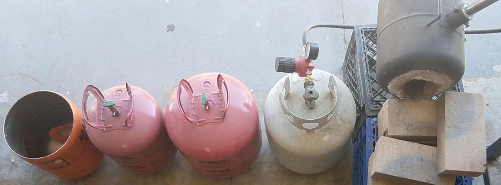
The smaller helium tank is the same size as the refrigerant tank but it is lighter weight if you worry of wall thickness. When I cut it open, I will measure it's thickness compared to the refrigerant tank. They are both 9.5 inch cylinders. With the ends cut open/off you get between 10-12 inches in length depending on how much you cut. The larger helium cylinder is pretty much the same size as a 20lb propane tank. It is 12 inches in diameter and gives the same 10-12 for length. Quite thinner wall then the propane tank which would make for a lighter forge.
You can see part of my first forge which is a refrigerant jug forge.
-
I do not mind having to work or experiment in order to use the Zircopax. I am looking for other members advice/experience on the subject before I start experimenting. I am looking for the re-emissivity for the energy savings. I used ITC on my last forge and from what I have read here, because of the kaolin clay, it sounds like it may not be the best thing to use for forge purposes. While I have read Matrikote and Plisix are used with good results by others, they seem to be more of an armor then an energy saving re-emissive coating. I may be missing something. They both are missing Zirconium Silicate or might have very low unstated percentages of it. I thought I had read that ITC has a very high percentage of Zirconium Silicate. I am seeking a kiln wash for re-emissive qualities, not for armor qualities. If I can have both in one, that would be great, but if I can't, energy saving is more important then armor for me.
-
After seeing the steveomiller's about the Plistix, I started to question the Metrikote sold by Wayne.
The only thing I could find was for Matrikote 90AC which I believe is what we are talking about:
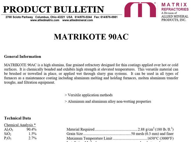
As you see, the alumina oxide is a few percent lower, the silicon oxide is very close, they state phosphorus pentoxide, and a bit over 5% unstated. Below this screen shot of the MSDS is stated "*Proprietary ingredient not included in chemistry." No stated zirconium. It's seems to be something that is strong at high temperatures. Like the plistix, is says nothing about re-emissivity or energy savings. It also states a maximum temperature of 3000F. Plistix SDS states a melting point of 3400F and further into the document it includes 0.02% Quartz, 1-5% Aluminum Phosphate, and 1-7% Bentonite.
Matrikote MSDS: http://alliedmineral.com/app/docs/pdf/reverberatory-furnace/MATRIKOTE 90AC.PDF
Plistix SDS: http://plibrico.com/uploads/MSDS/sds Plistix 900F.pdf
Move on to ITC-100HT:
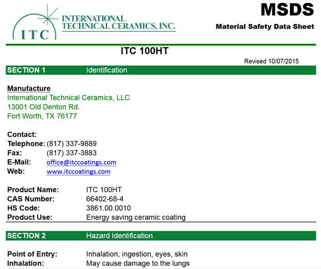
The mix is not stated, but the product use is. It states "Energy saving ceramic coating" and has a melting temperature above 4000F. I tried to follow the CAS number and found a lot of "Proprietary Formulation" road blocks. I did find this page: https://www.lookchem.com/Ceramic/ which mentions ceramic but that page is above my chemistry pay grade. It doesn't seem like it is talking about ITC though.
ITC MSDS: https://www.norheatinc.com/wp-content/uploads/2017/11/ITC-100HT-SDS-2015.pdf
I am looking for a good kiln wash with for re-emissivity. I have read that ITC has kaolin clay which doesn't get hot enough to vitrify. The alternatives that Wayne offer don't seem to have the re-emissivity as their intended goal. I can't seem to find the source but I had read that Matrikote was not to be applied to hard refractories but to the ceramic blanket directly. I am wanting two to three inches of rigidized ceramic blanket, 1/2 inch of Kast-O-Lite, and a kiln wash. I have read that several people have applied the Plistix or Matrikote directly on Kast-O-Lite without problems from either and most say they did help with heating the metal.
A few questions which I know are dabbling to the experimental side. Some of which I may have to do. Does adding Zircopax Plus to either of the above, probably Plistix, scream out a bad idea to anyone who knows more then I do about this stuff? Is the Zircopax Plus with 5 % bentonite a better idea still, aside from being cheaper? An alternate idea, does adding either of the above between the Kast-O-Lite and whatever re-emissive wash I end up using make any sense to anyone? Possibly to protect the Kast-O-Lite. The Kast-O-Lite is pretty tough stuff.
Has the dust settled on the Zicopax Plus with 5% bentonite or with the veegum? A question for Frosty, have you produced any sort of a hot face wash with the Kast-O-Lite mixed with Zircopax that you are happy with? Zircopax is inexpensive so I am willing to experiment. Based on previous readings about, I believe Mikey, using water to separate some ITC, I am guessing the Zircopax Plus with the finer Zirconium Silicate is going to be what I want over the plain Zircopax?
Forgive the long legs and overthinking on this one. Forgive me if any of these questions have been answered elsewhere. I have read the Burners 101, Forges 101, Narb, and T burner threads and so there is a lot of overlapping information in my head.
-
Frosty: Back on page 40, John in Oly,WA posted a image which demonstrates the concept of the vortex burner. It is a linear burner with an impeller axial fan at the air inlet reducer. The purpose of the fan being to increase vortex down the mix tube more so then to provide air force. Mikey said they can be run without power to the fan as just the vanes are enough to promote swirl of the induced air but the main purpose is to run the fan to increase the output capabilities of the burner based on the vortex. In John's number 4 and 5 videos, the burners are skipping the fan all together and the white plastic things are just vane devices to cause the induction air to swirl.
-
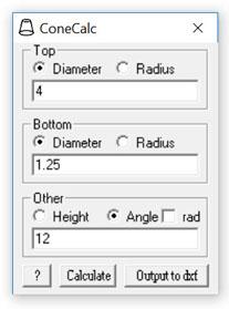
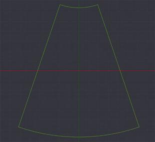
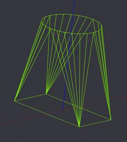
Back on page 35, G-son gave a cone making tutorial. I had written a small program a while back that will layout the template. It can output a dxf file which can be used for scale printing or cnc cutting or give the numbers for manual layout. It takes the top and bottom radius/diameter and either a height or angle to output. I originally wrote it to produce the frustum for a cyclone separation system but it would work equally well to produce cones for burner purposes. I have found that a frustum in light stainless can be rolled with some round stock of the right size, my own thigh, and a little sweat.
Here is a shot of the program and it's output file:
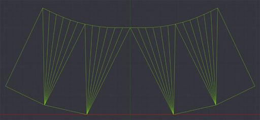
I have also written a less refined but very functional square to round transition producer. This was for some HVAC work but might be useful to someone here. Here are a couple of images of it's outputs, one flat layout, one 3d model:
Both programs are a little over 50 KB each but zipped are under 12 KB each. Less then the images I uploaded here. They are legacy VB6 applications but still work properly with Windows 10. If anyone is interested, let me know and I can upload one or both.
-
I'm new to IFI, late to the party. I have read the NARB thread, Forge 101, and Burners 101 entirely in the last couple of weeks. It has been a pleasure. A bit daunting at times as there is so much there. I will have to read them all a couple more times to get it all in. Calling it 101 after reading it all makes me laugh. As far as homebrew is concerned, it is as cutting edge as I have found. Vortex and NARB burners... certainly not freshman material. We have to be pushing 500's at least, right?
I cobbled together a Freon forge a bunch of years ago reading Ron Reil's pages and any information I could pull from Larry, Wayne, and the hybrid burner page. Somehow I hadn't stumbled across Mr. Porter's book back then. While the forge is good and serviceable, I always wanted more information. I also developed a bit of an obsession with burner design. I can only imagine it's a similar itch, that Mikey has. It has been wonderful to feel almost overwhelmed with information. Not only that but information from Frosty and Mikey. Information they(you) are treating as open source. Two members who have produced burners of their(your) own which work so well they are known by the blacksmiths. Members who are humble enough that we can trust the information they(you) share. If that wasn't enough, their(your) burners are two ends of a spectrum in my eyes. One being as KISS as possible while still being a powerful burner, the other being as precise as possible which might make it a bit pickier but also makes it very adjustable. You disagree at times, you agree at times, others bring in more tangents to the conversation. Like I said, it has been a pleasure to read and gain understanding.
That said, I am a technician by trade. I fix all kinds of stuff. I get to play with all sorts of commercial burners. As I work on them, I will start getting pictures. I hope that I can bring a lot of information to these threads, at least as I understand their workings. I see venturi burners, Bernoulli burners, jet ejector burners, power burners, and sometimes combinations of these. I see these in both Single Outlet Buners(SOB) and Multi Outlet Burners(MOB). Manufactures nomenclature varies but typically MOB's are called high efficiency burners and most of them are Power Aspirated(PA). Not all though. I do work on a MOB which is 6 inch by 10 inch which is NA. They employ large numbers of much smaller holes. The way I see it, more smaller holes allows the block to be thinner while still maintaining laminar flow. This also causes much more even heat and allows for high velocity flames which are short which means hot without impinging material below. I suspect the thinner burner block cools better with the incoming mix gas. That, along with the high velocity, prevents backfire. I believe, the number of holes is selected to match the input pressure created by a jet ejector into a venture. I will get pictures as soon as I can. That said, this burner works on lower pressure natural gas with a much larger orifice then our high pressure propane burners. It does go infrared but it is open air so I don't know what it would do in a forge as far as temperature and I imagine the increase in back pressure would cause it to not function properly if at all.
I look at burners as three major pieces. Flow input, carburetor, burner head. Flow input can be powered or induced. By carburetor, I mean any device that mixes fuel and air. By head, I mean the device that the flame burns at. These pieces often combine functions. My goal is to build a NA, adjustable, high induction carburetor. After that, to use it with a multiple outlet burner. This would be my holy grail. I think powered burners are easier, even though people mess them up as often as NA for the same reason, lack of understanding. While I know that I could power a low power blower remotely, I'd rather not be tied to electricity when I don't have to be. I also have a desire to build micro burners. Not for practicality, just for fun. If I was always practical, I wouldn't be a blacksmith.
I will have lots of questions, hopefully good ones. I will try to ask them in the appropriate threads. If they are already answered somewhere, please direct me. I will fully search for them before I ask but IFI is awesomely gigantic. For now, only one train of burner questions. Sort of burner questions. Idle valves. Are they worth the effort? Does the forge chamber maintain a high enough temperature to not have to wait upon return? Does it cause thermal cycling of the wall materials in a way which they won't like? Does it require a choke which should to be adjusted when set to idle? I would guess several of the questions will be answered with: it depends on the burner.
One last thing, as stated, I am a technician. I will give any information I can that I think helps anyone, I will not state it as fact unless I know it is. I am reasonably sure of the things I know but I assume that anything I know can be wrong so please point it out if you know it is wrong so I can educate myself and not be a future source of incorrect information. I also work on refrigeration systems so if you happen to be in or around Boise, Idaho, I have an almost unlimited supply of refrigerant tanks. We scrap them as they have no other purpose and I can fit anymore into my own garage. I believe they are a bit heavier wall then the helium tanks for those who want that. My next forge will be the larger disposable Freon tank as it is 12 inch diameter and I suspect it will make a great "small" oval forge. After that, I want to build a NARB powered K26 brick mini forge. OK, enough about forges in the burner forum.
Thank you to all have contributed to my understanding of burners and forges. Sorry for the long winded introduction. Forgive any typo's or miss words, I had a heal event a few years back that muddles my noodle from time to time.
-
Jbradshaw - On page 6, Buzzkill posted February 18 a 1/2" version. Forgive me if the link does not work, this is my first post on IFI.


Burners 101
in Gas Forges
Posted
Here is the flame Mikey is referring to: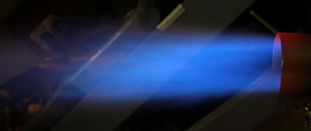
I have been experimenting with burners air inlet shapes to learn. This is a 1/2 inch burner with an 0.025 mig tip for the jet. The nozzle is a temporary nozzle as there was some excitement to see it lit, so the flame is not concentric. You can barely make out the vice grips holding the tabs on the stainless sheet metal nozzle in the lower right.
I will be adding a better nozzle, playing with mix tube length and changing the jet size to further experiment. I will try to get better images without the back drop clutter. I was so focused on getting an imagine which had the color I was witnessing that I didn't think of back drop.
This particular burner was an attempt to force the induced air to spin down the mix tube to see what it does to the flame. At low pressures ( < 5 PSI), the spin is very obviously noticed in the flame but at higher pressures ( > 10 PSI) the flame moves fast and straight. I believe I remember reading Frosty talking about toroidal flow down the mix tube so I am not sure if the spin helps or possibly gets in the way of toroidal flow. It seems to burn very well. I took it up to 20 PSI which burned stable and angry.
In my current forge, I have a modified side arm burner. It's flame is much shorter, slower and bushier. The forge gets hot enough to weld and the burner does not produce a flame like in the image. This experimental burner flame is very straight and longer. I am not sure if that is good or bad as far as forge use. I also have not experimented with the mix tube length to see how it changes the characteristics.