rls1160
Members
-
Joined
-
Last visited
Everything posted by rls1160
-
Wow, looks like 4 Ausie's, that will keep you busy!
-
Looks very comfortable, probably nice a warm when sun heats up the coal pile.
-
As he should be
-
Good guard dog and or waiting companion. Husker has the best seat in the house!
-
Thank you Frosty, Merry Christmas to you and your family. Thank you George, it's going to be a cold couple of weeks coming up here in Wisconsin. Bundle up everyone
-
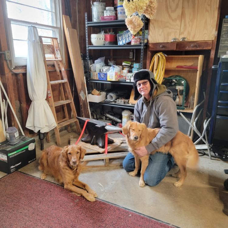
Today was a happy day! New anvil arrived and the girls came to check it out. KC is the 8 year old and Dale is the 6 month old. The baby in the middle is a 250# Fontanini anvil. Merry Christmas!
-
Frosty Thank you for the input. I went through a ton of pages in both the 101 forge, 101 burners and ribbon burner pages. Yes I invested time effort and money into a casted D-shape forge using the refractory I used for the burner. I learned alot through the process and by the mistakes made. My local refractory supplier can get Kast-O-Lite 30 LI in 1-2 weeks. So my plan is to use the IFB bricks to figure out sizing. The forge I casted is 15" deep x 12" wide by 9-3/4" to center roof. It is D-shaped and has interior cavity volume of 1,515 cu.in. a bit less than 1 cu.ft. I got to that size by based on what I typically forge. A 4" x 6" pine ridge ribbon burner had a forge capacity of 1 to 1.5 cu.ft. I didn't feel it was appropriate to use the the general approximate 350 cu.in. per burner as a guide as referred to I'm many of the iForge posts throughout the burner and forge sections. It's very difficult to determine the btu output on a multiport burner so It felt a bit like trial and error to find thebsweet spot. So rather than continue to waste others time on the forum I decide to move forward with the information and productvI had on hand. I knew the refractory I used was borderline on the based on what I had leaned via iForge pages. The forge bottom feed burner table is great, I really like the flexibility it provides for what is used as the forge cavity. So what to do now? I can purchase Kast-O-Lite 30 LI and recast. If I recast is my cavity size workable? What thickness should the casting be, my current one was 2" thick. I have 1" thick Ceramic board that could be used as an other wrap insulator to the castable. Or I can use the 2300 IFB I have to test sizes. Once I figure that out, purchase 2600 or 3000 IFB bricks and just settle on a brick pile forge. The internal cavity size of the IFB brick pile test forge is 14 1/4" deep x 9-1/4" wide x 9-1/4" high that equates to 1240 cu.in. I was able to get to a low forging heat but not forge welding heat. I did not expect to hit welding temps with a make shift set-up like it is. I am not a knife maker so I need something that will accommodate a bit larger form into the forge.
-
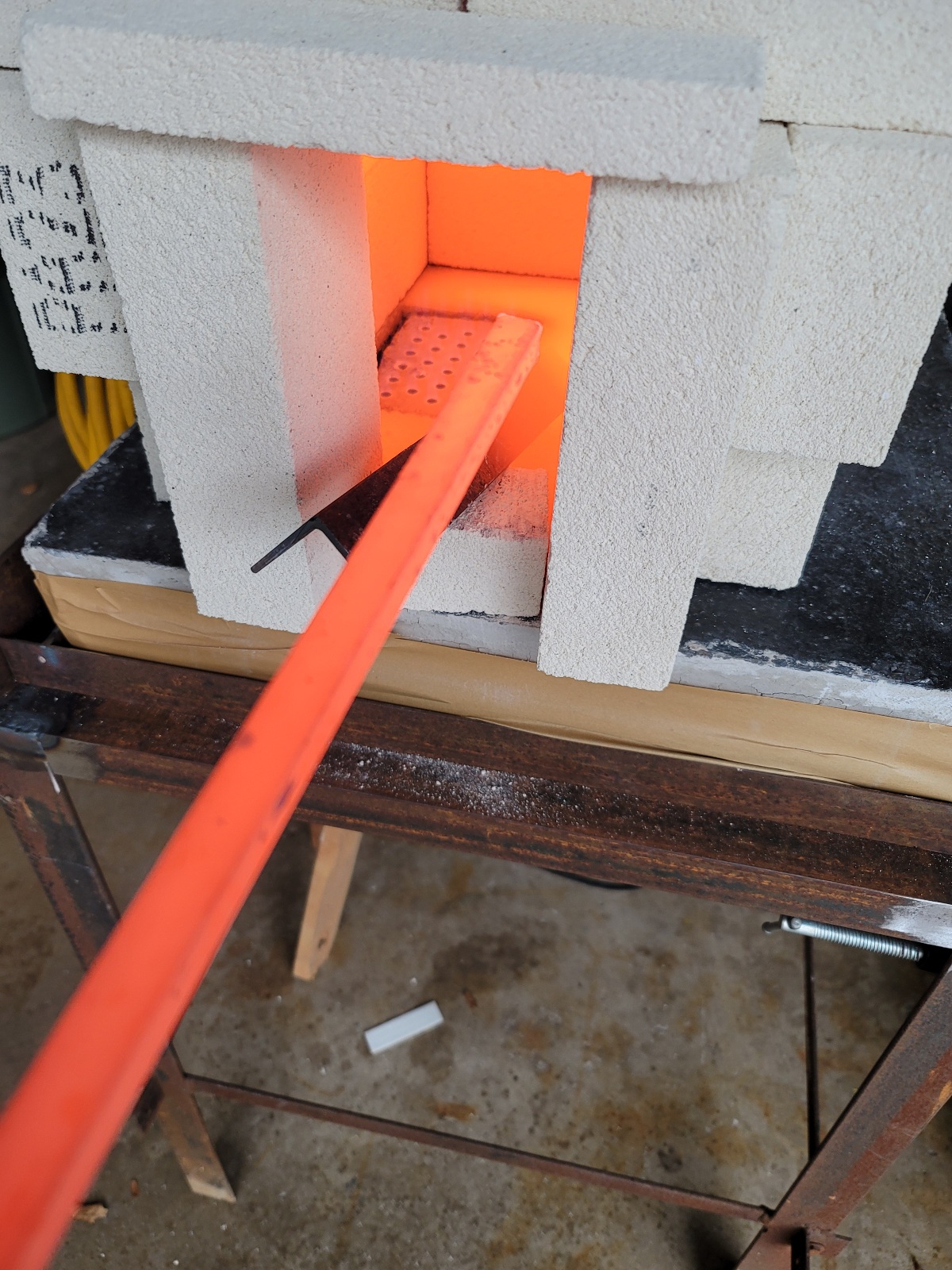
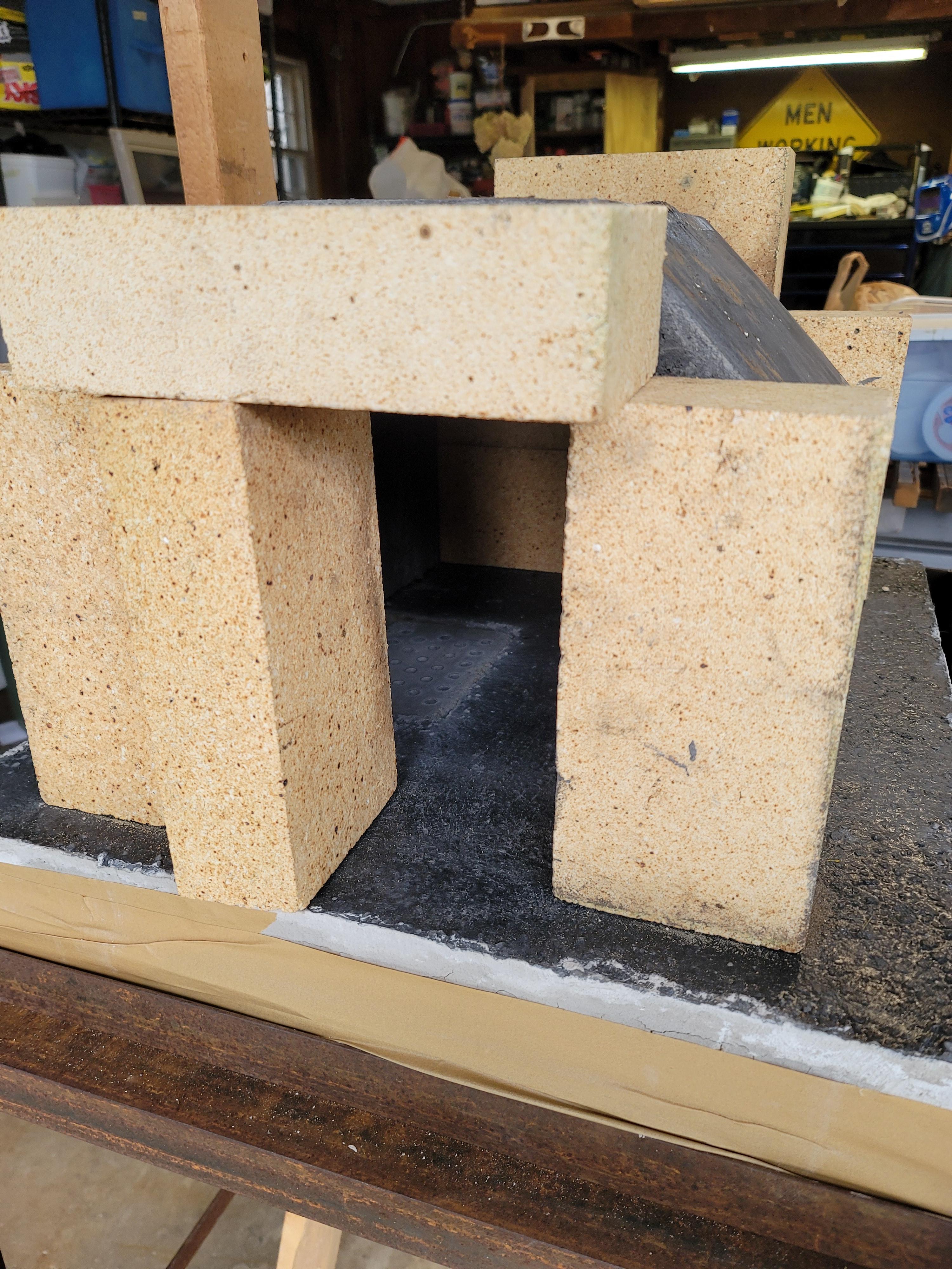
Update November 15th Well my HWI Versaflow 60 casted forge cavity has too much thermal mass and the product has a thermal conductivity rating of 7.9 so basically it socks the heat away from the forge preventing it from reaching proper heat. Today I crafted a makeshift brick pile forge for testing. I used 2300 degree IFB bricks without any IR coating. The results were amazing! I have not been able to find Kast-O-Lite locally there is a refractory supply house that can order it. What I am considering based on my tests today is to split the 2300 IFB bricks I have in half to make 1-1/4" x 4-1/2" x 9" bricks and mortar them inside the casted forge as a lining then coat with Pilistix. Is this a reasonable way to address the issue I am having. Or do I simply abandon the concept of a casted monolithic forge cavity in favor of an IFB brick pile forge until I can secure a proper insulating castable? 20221115_103754.mp4

-
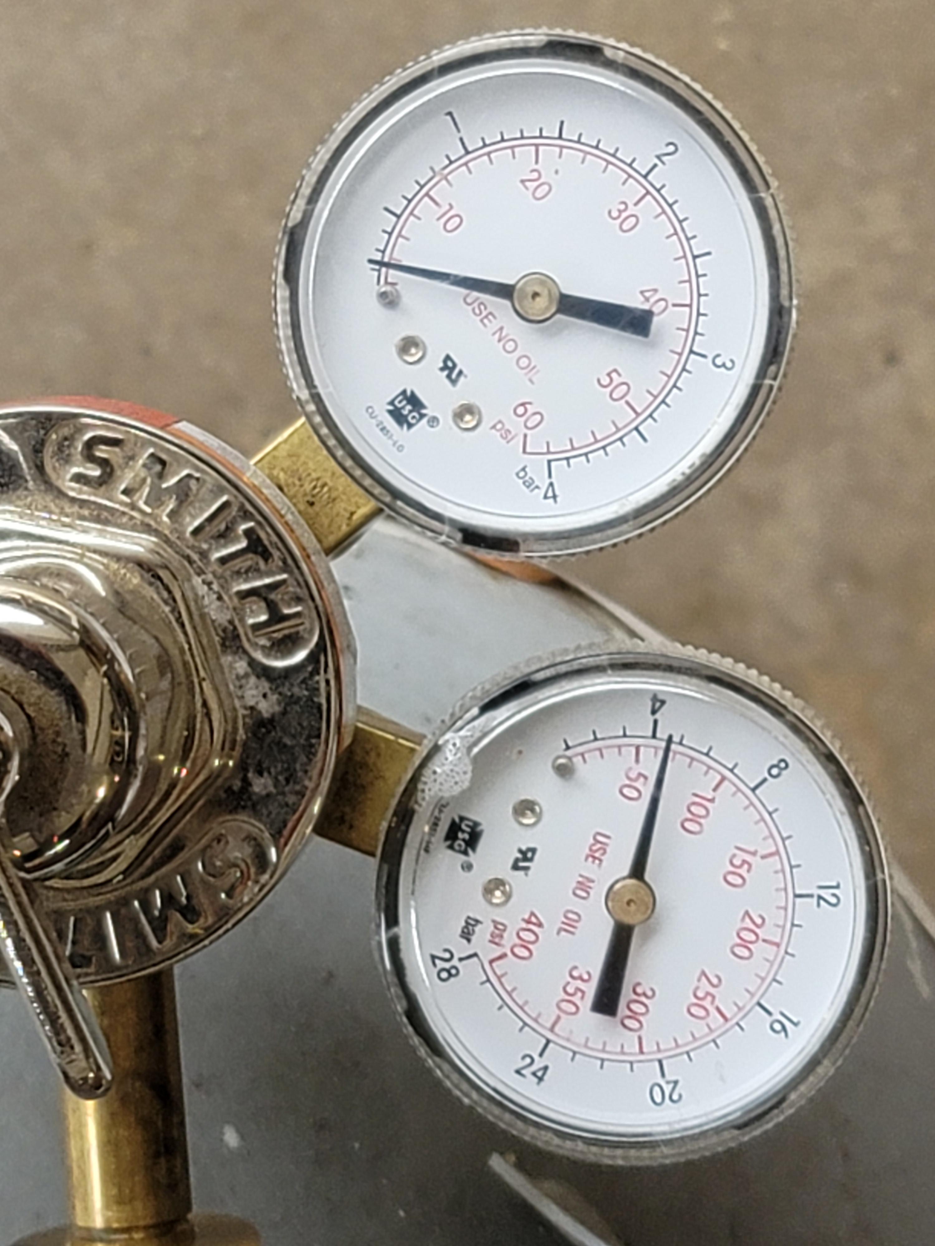
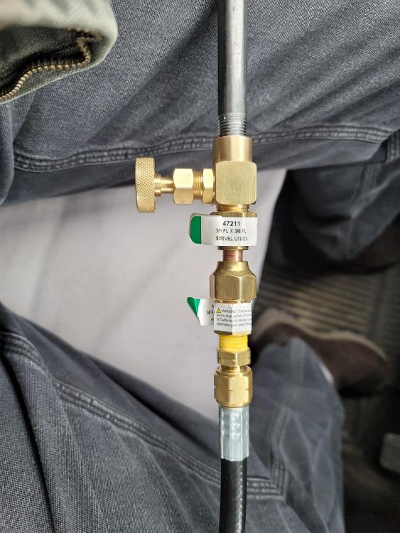
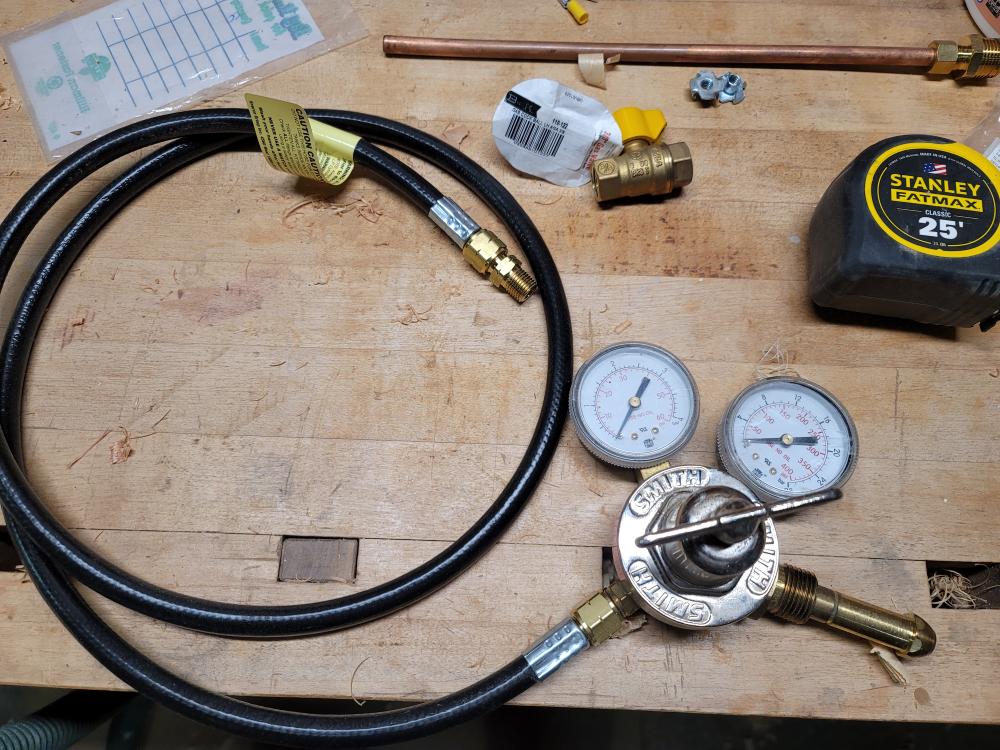
Irondragon, Thank you for the nice compliment. As for the regulator, it's a regulator from my propane gas cutting and heating rig. I had purchased that regulator long ago from my welding supplier when I switched from oxy-acetylene to propane to run my large rosebud torch and then converted cutting equipment to propane. A Cheaper and safer gas for cutting and heating. I will double check the model and specs to make sure it's good to go for propane. That you for the heads up on that one. Rick Irondragon I will look into how to reduce image size, sorry about that.
-
Latticino the internal forge dimensions are 12"w x 9-3/4"h x15.5"d. However it has a sloped roof (D shape) so I calculate something less than 1800 cu.in. or about 1 cubic foot. That burner was fashioned off a pine ridge burner that was spec'd for around a 1.5 cu.ft. cavity. I can tell you the thermal conductivity rating on tye refractory I used is higher than kastolite, I realize it's going to be on the higher end of thermal mass scale. The supplier was local and unfortunately I had the material before I discovered other materials with lower thermal conductivity numbers. Thank you for tyhe insights.
-
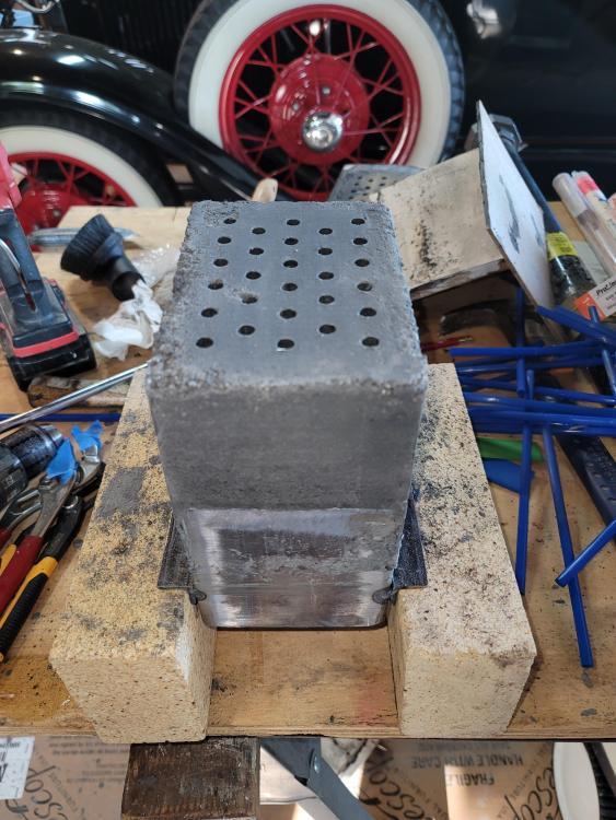
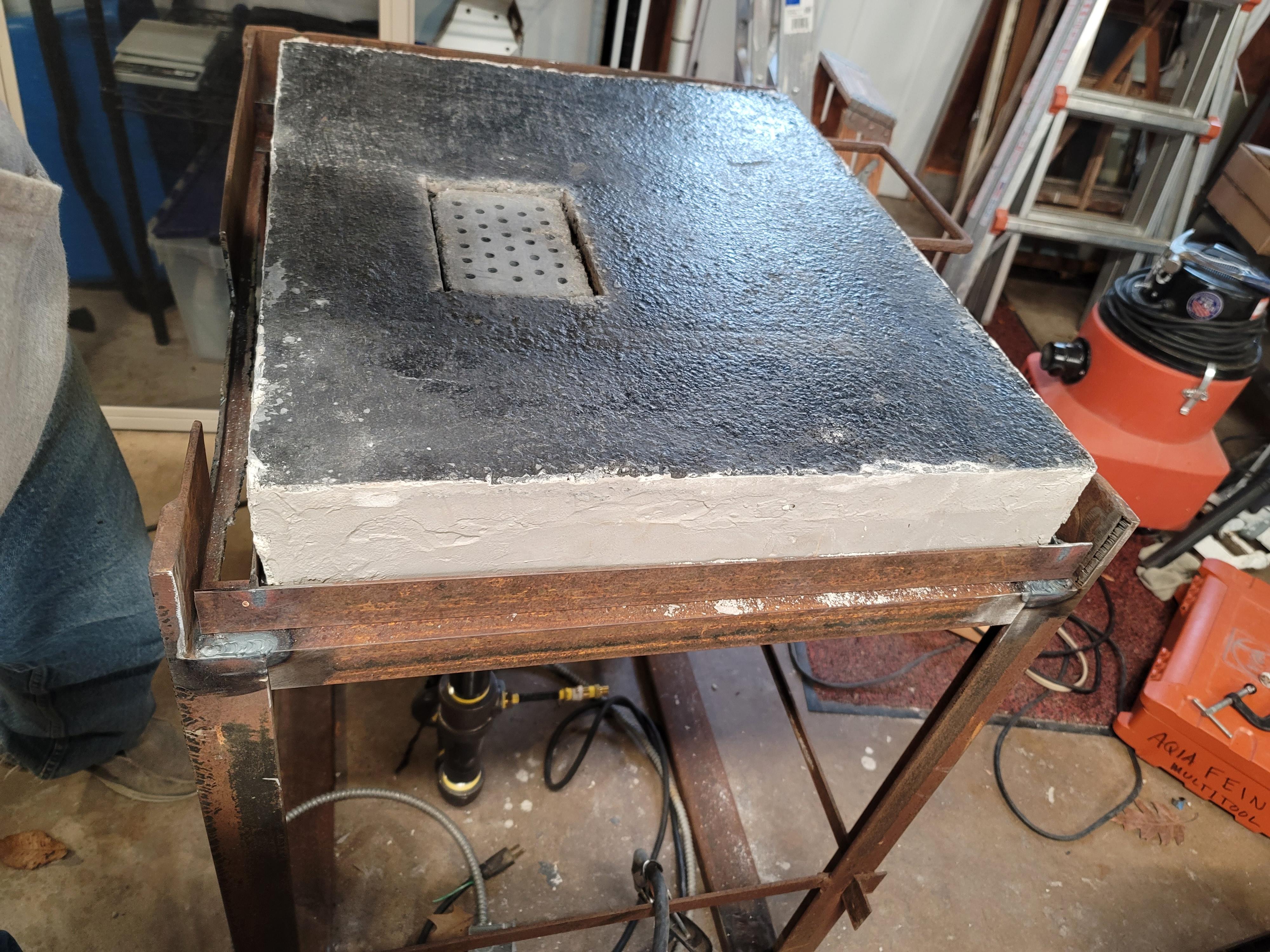
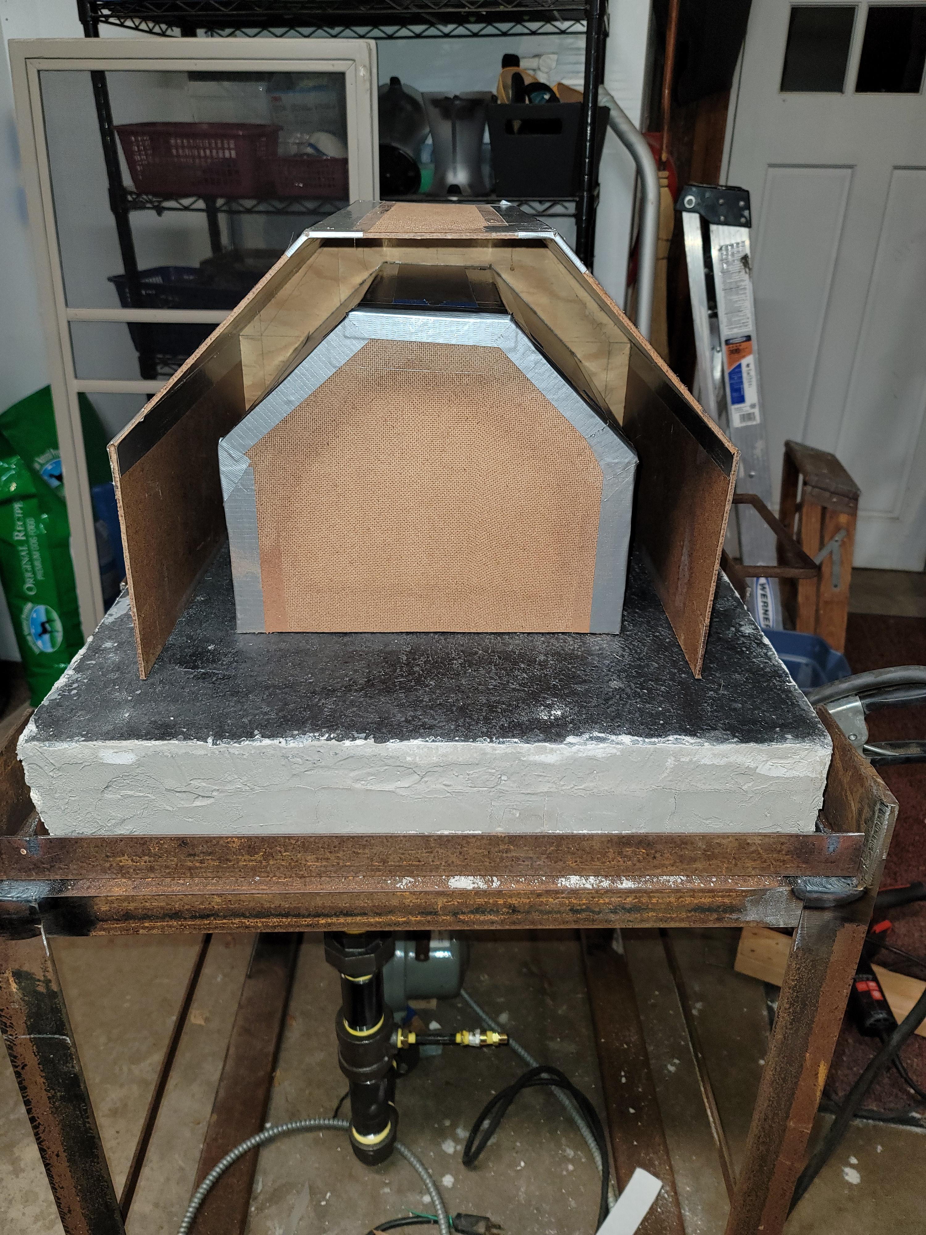
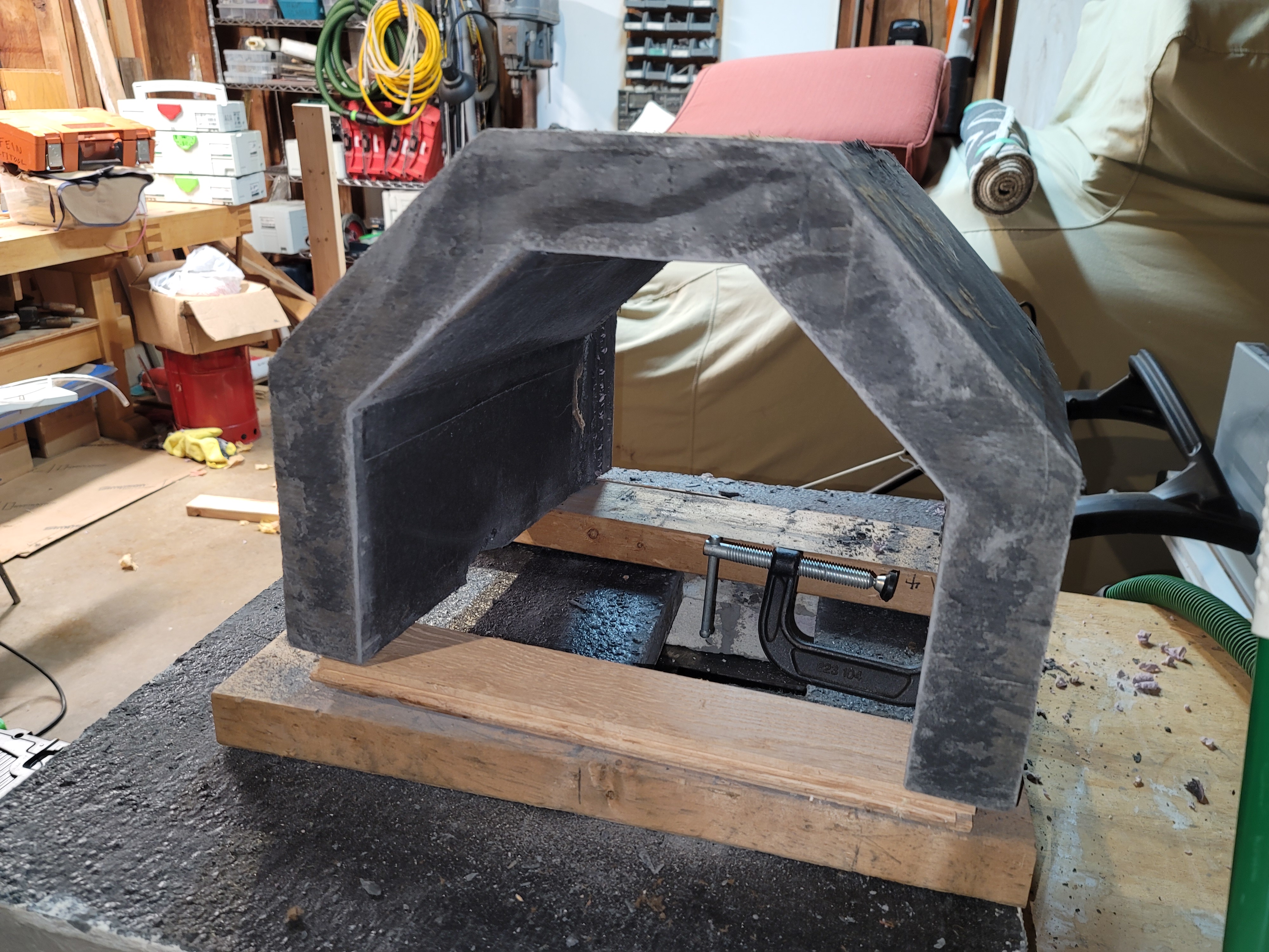
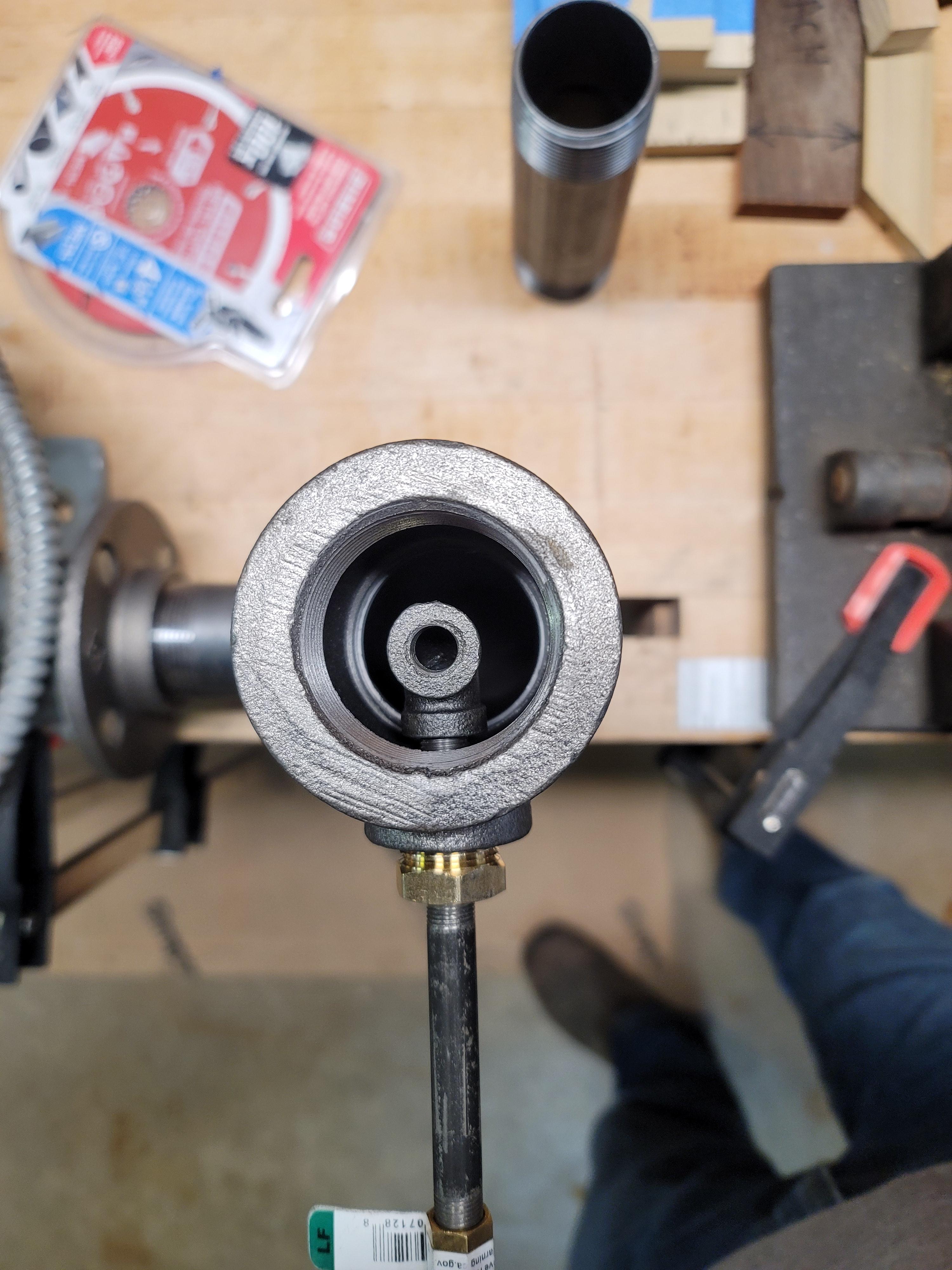
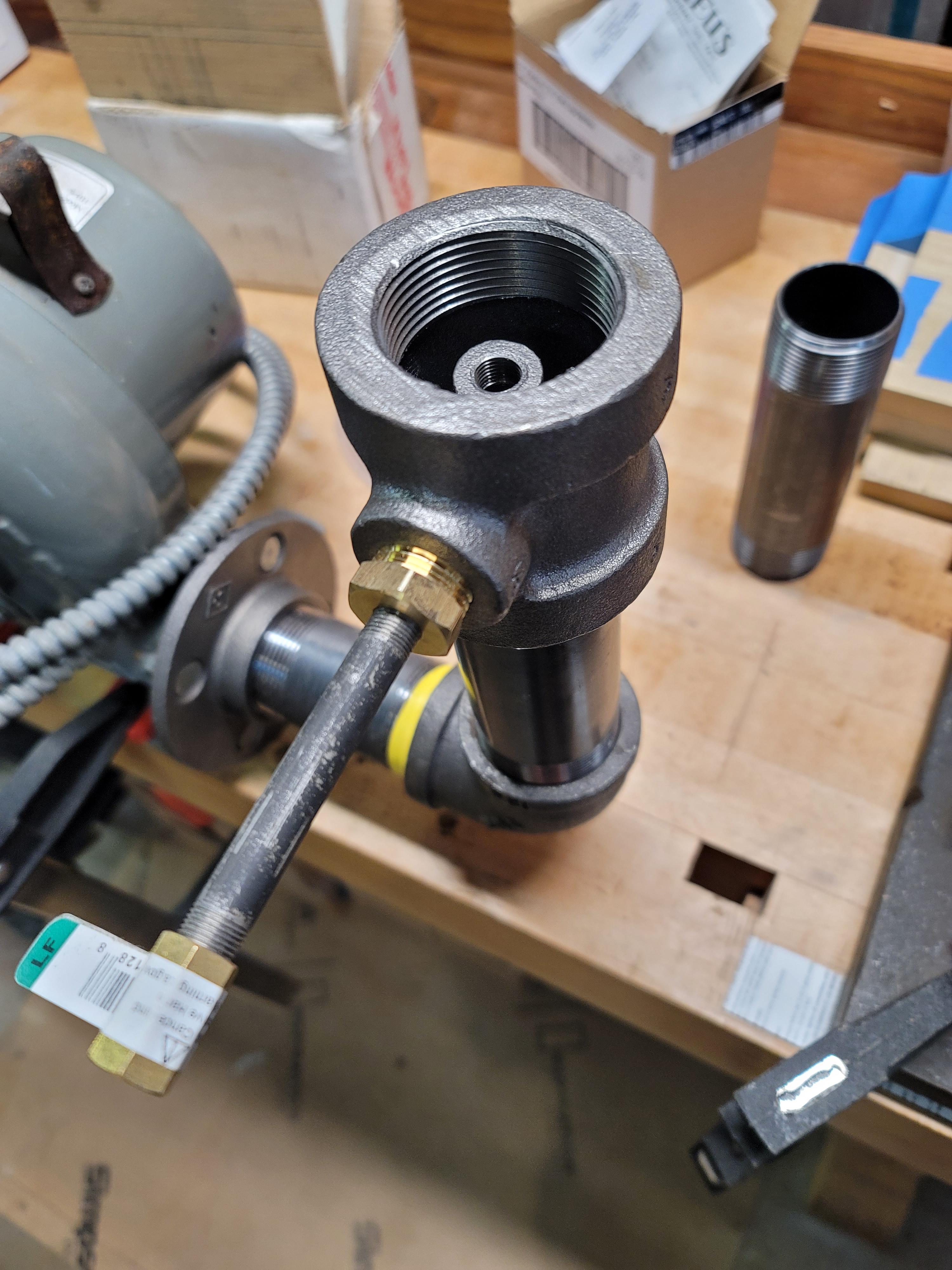
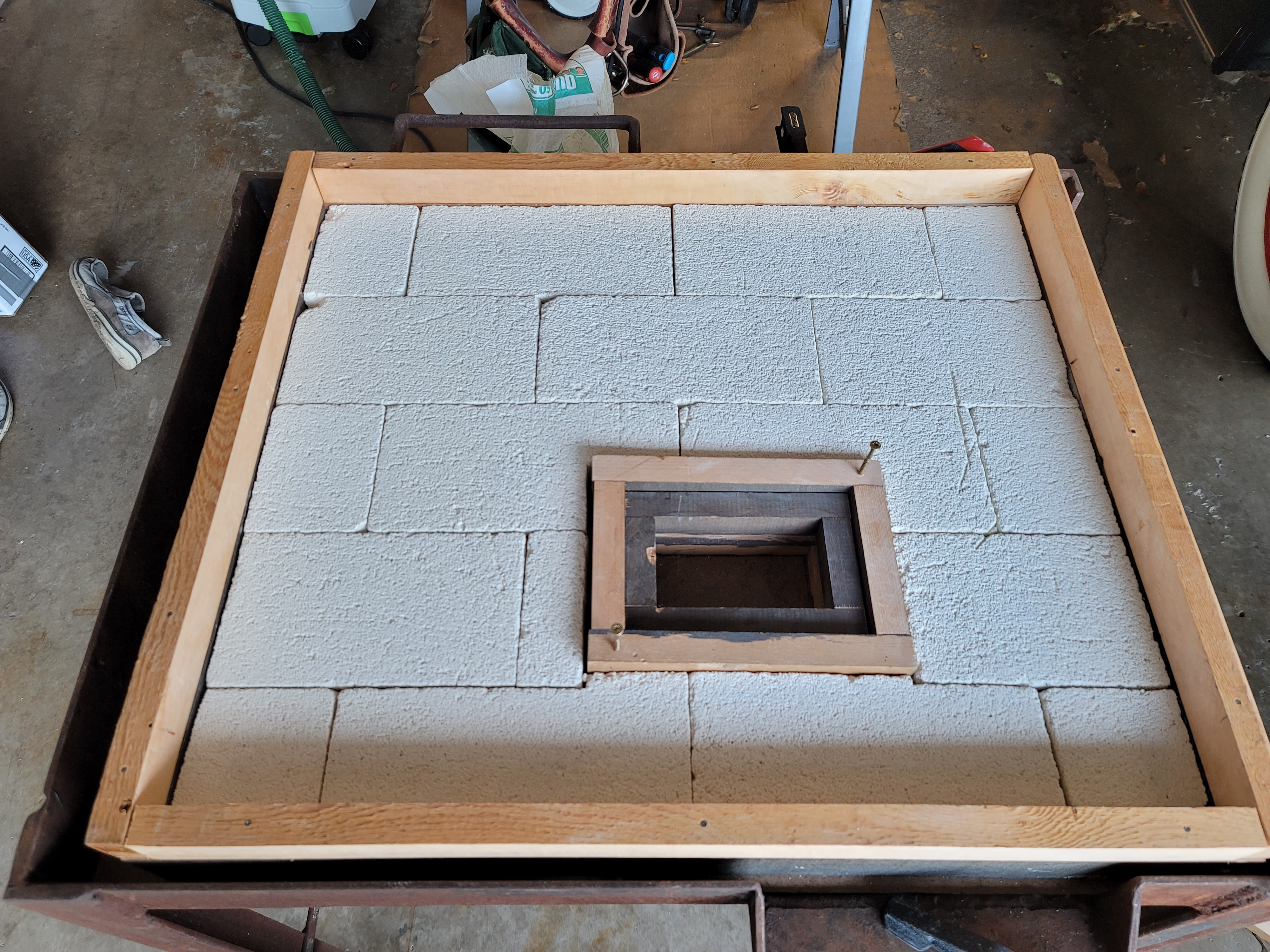
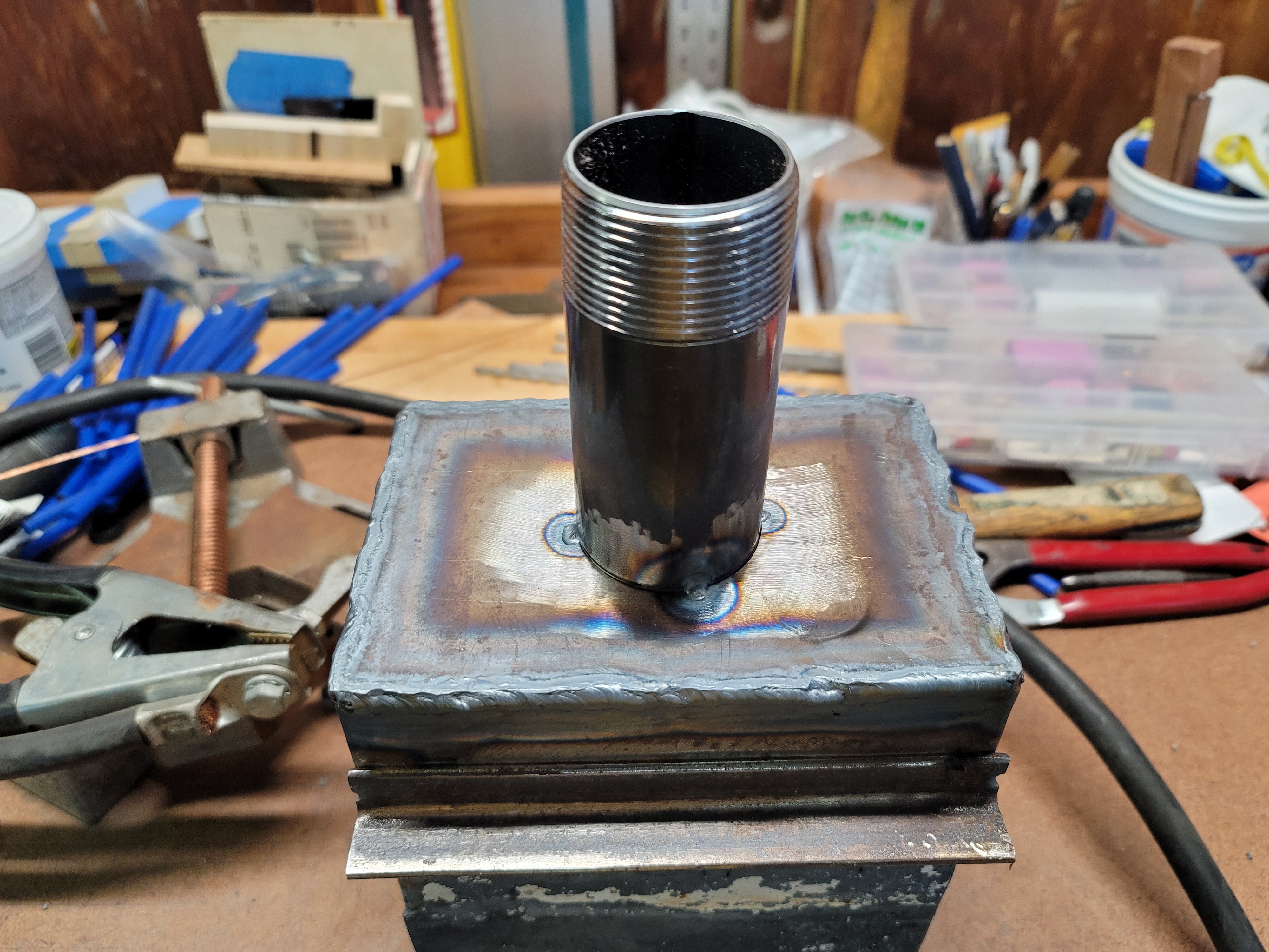
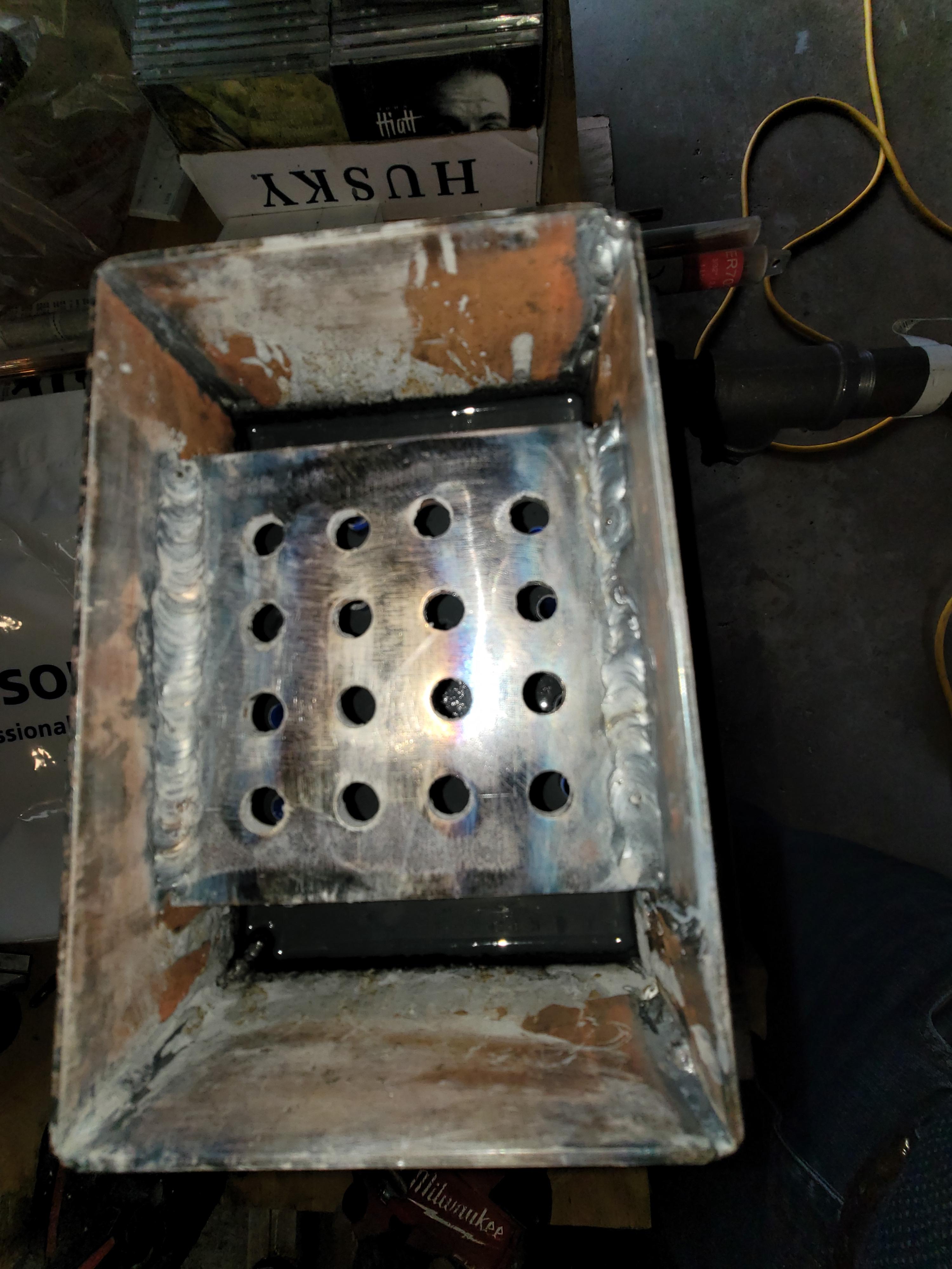
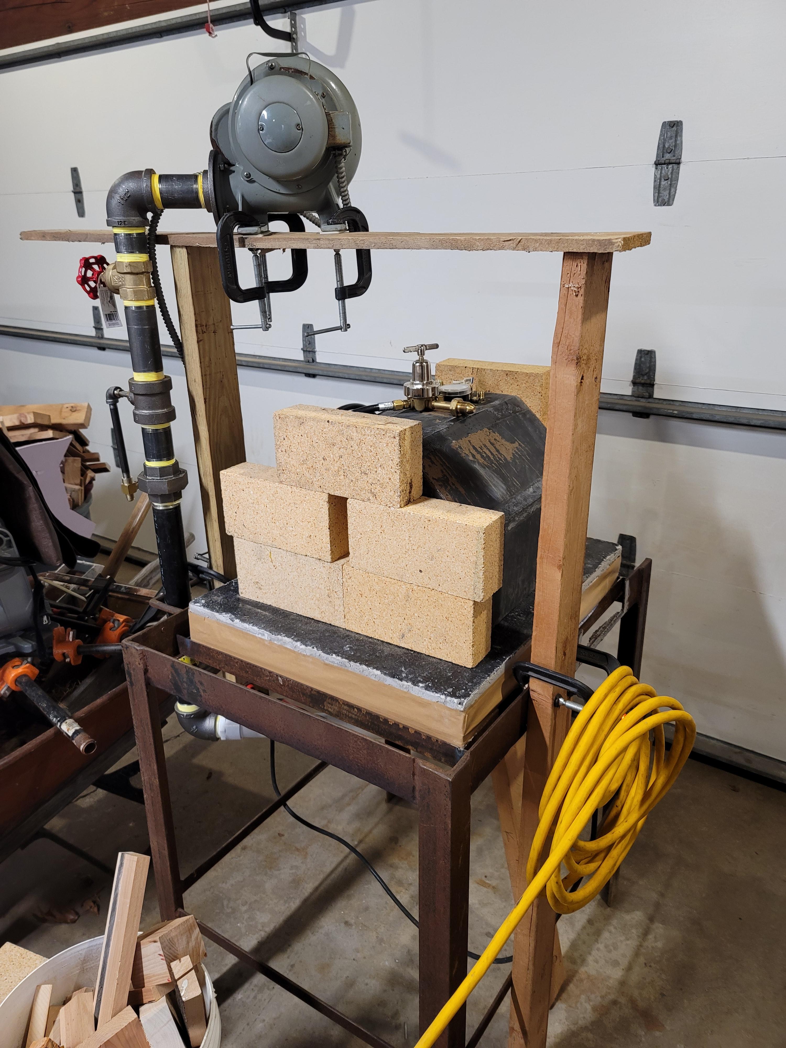
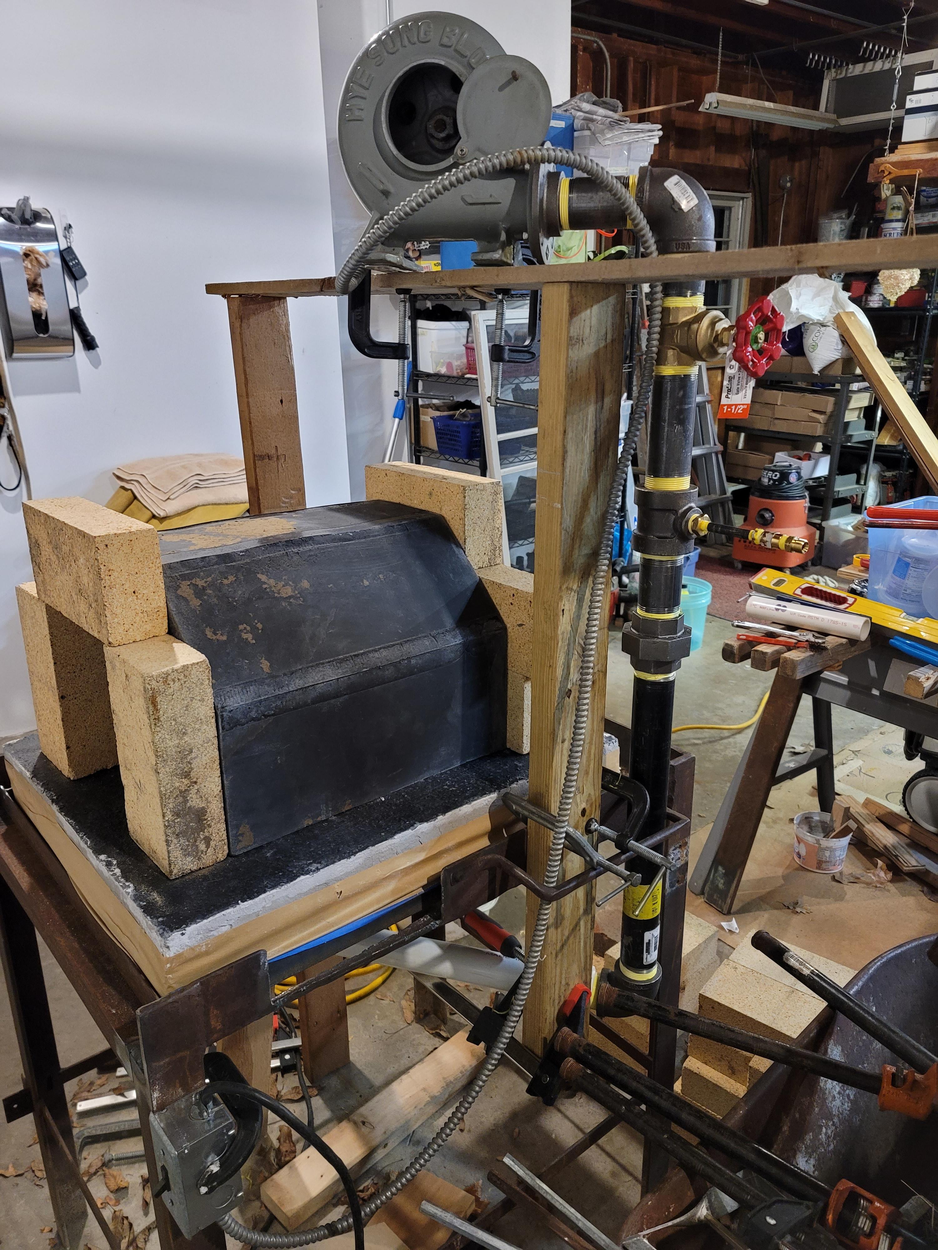
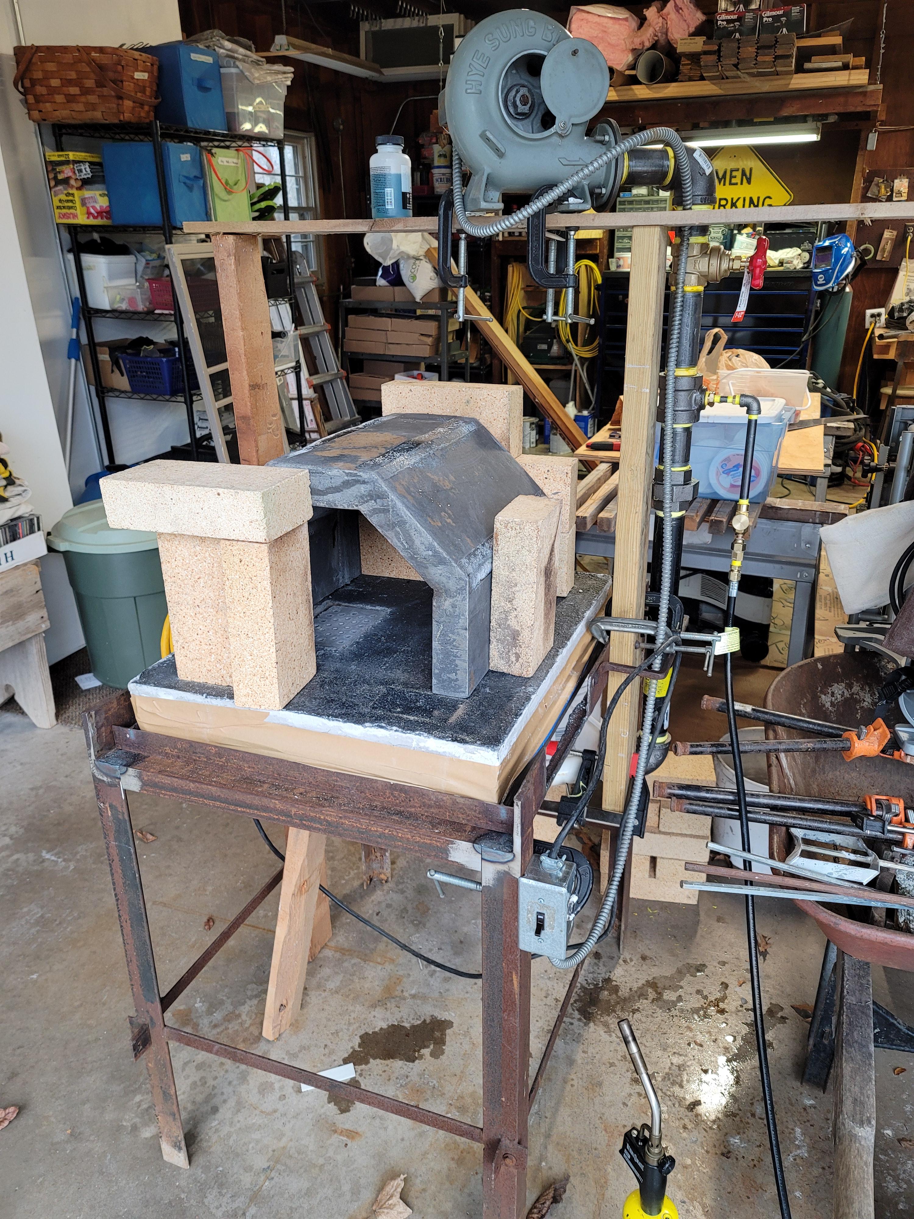
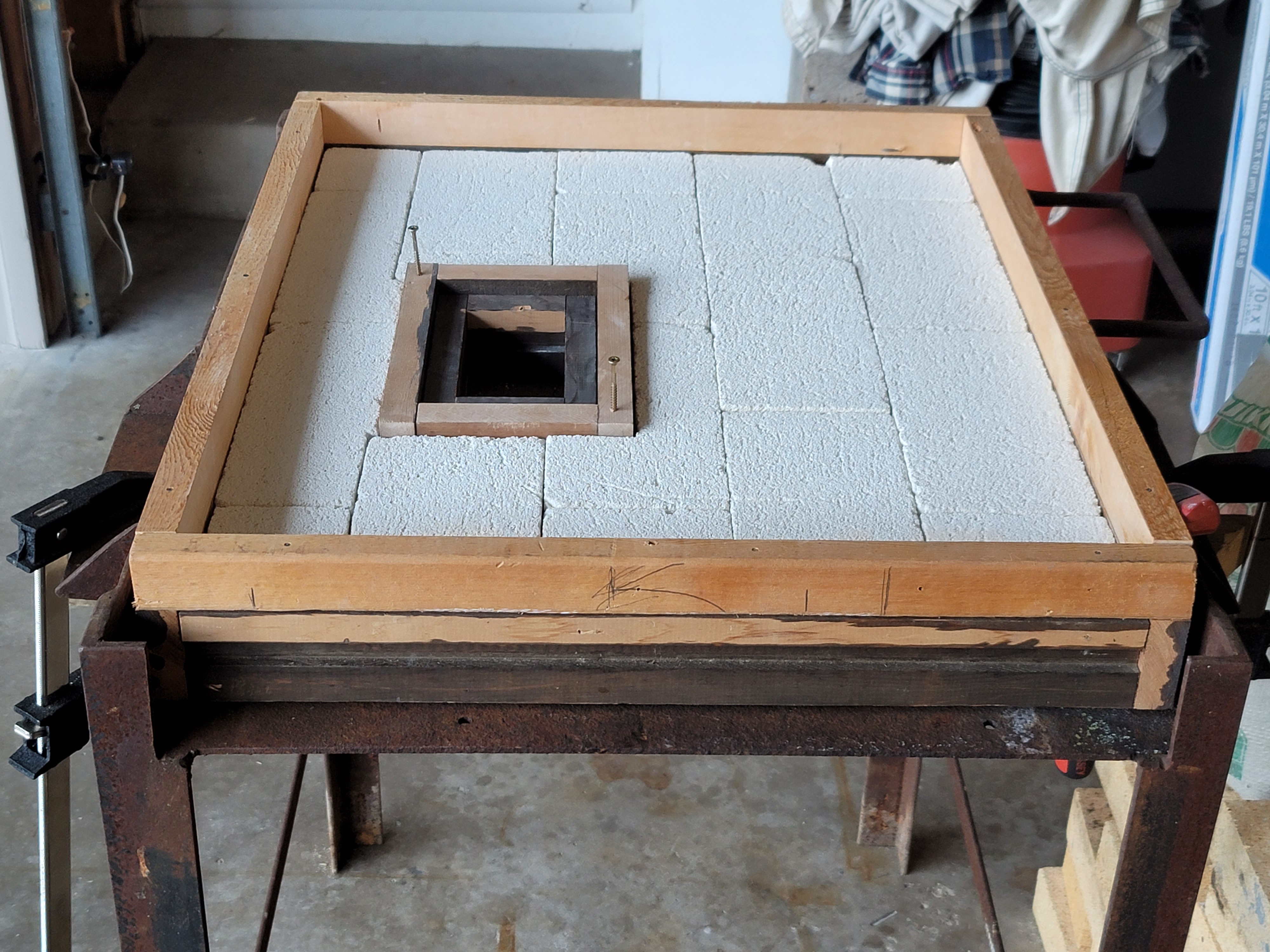
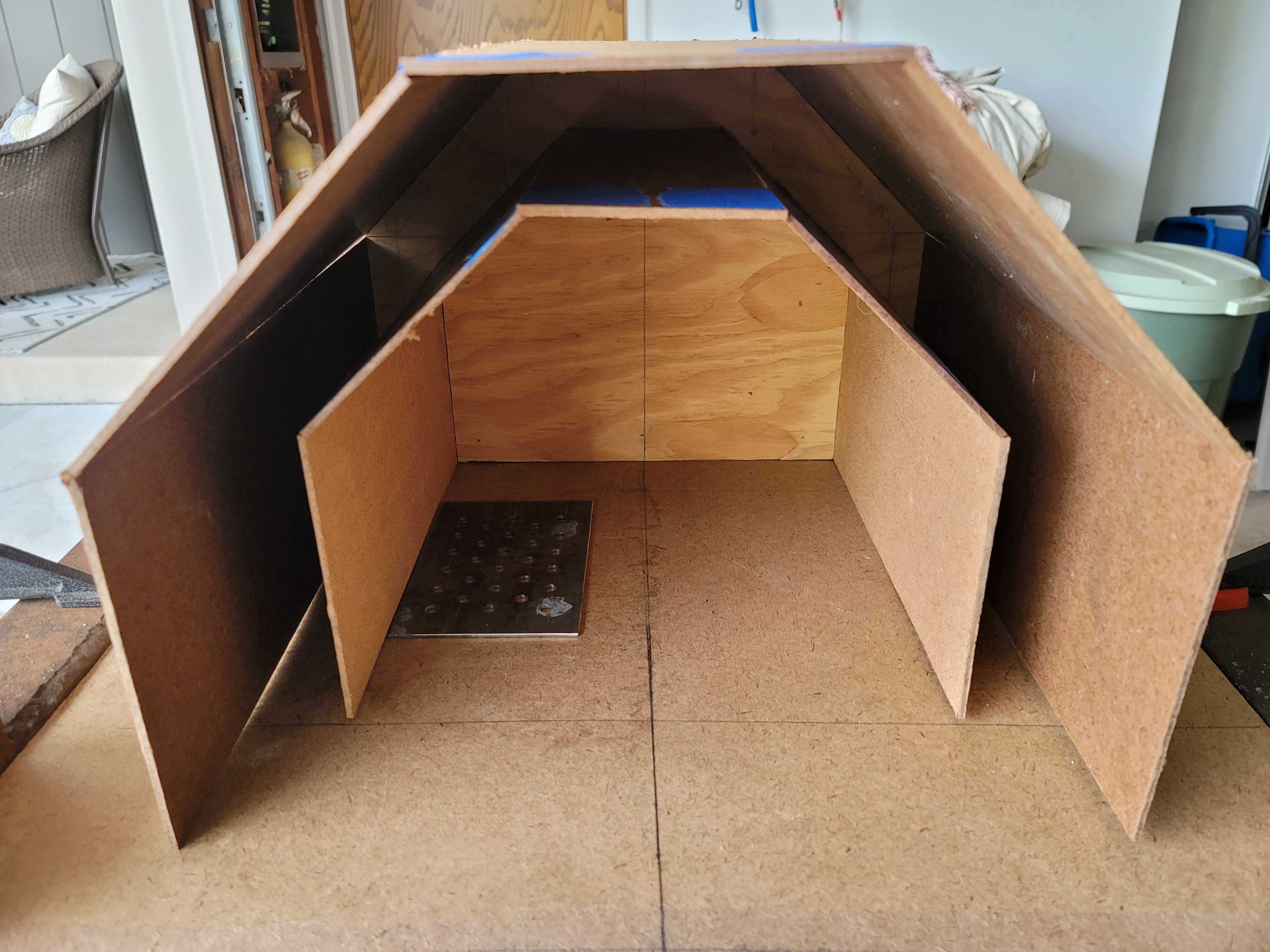
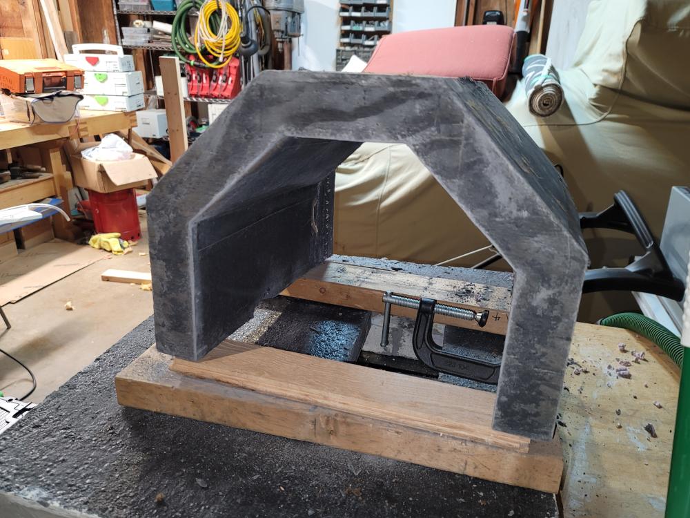
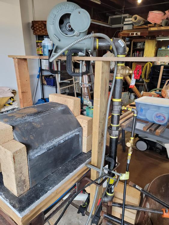
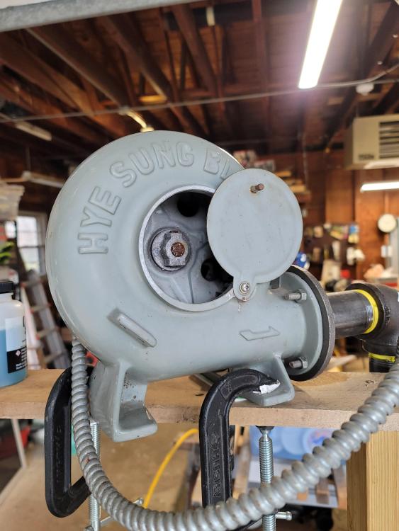
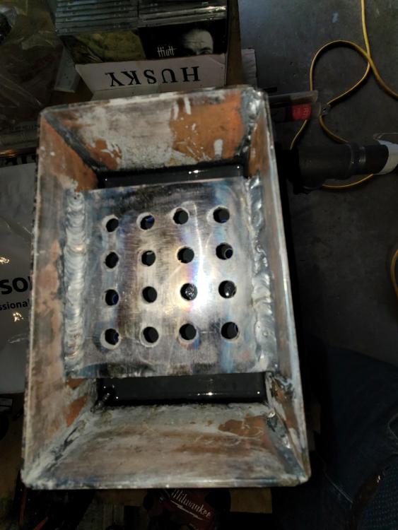
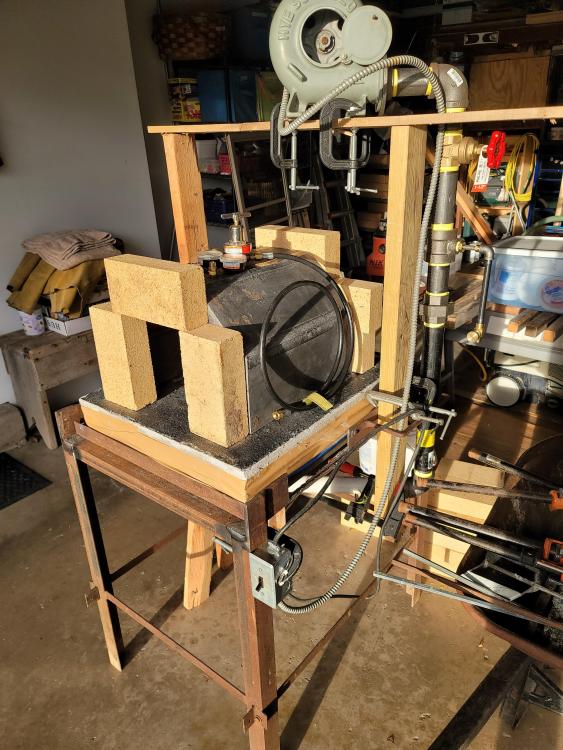
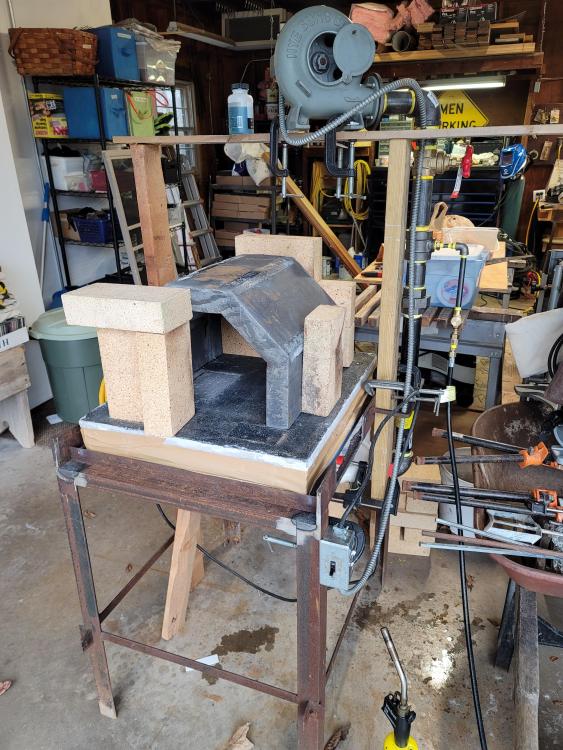
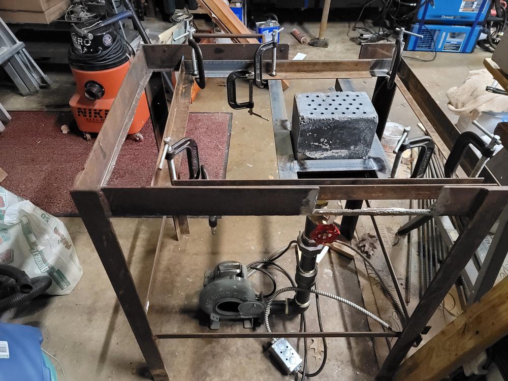
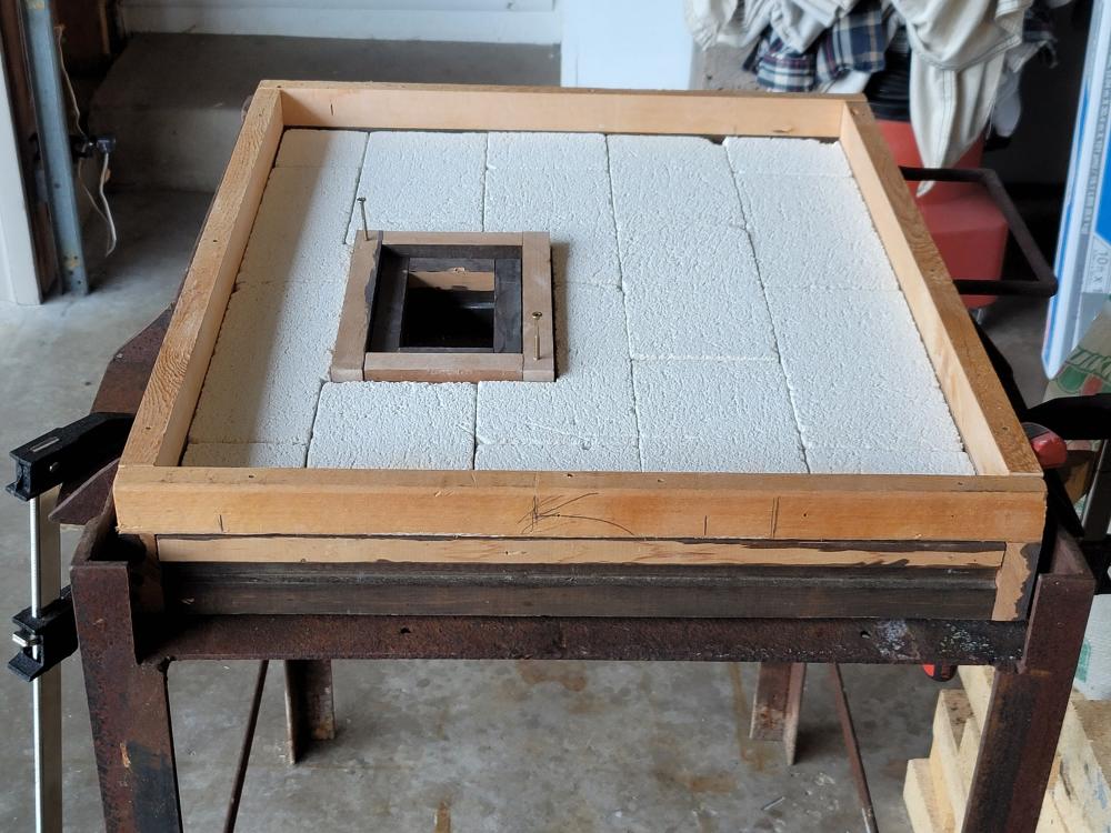
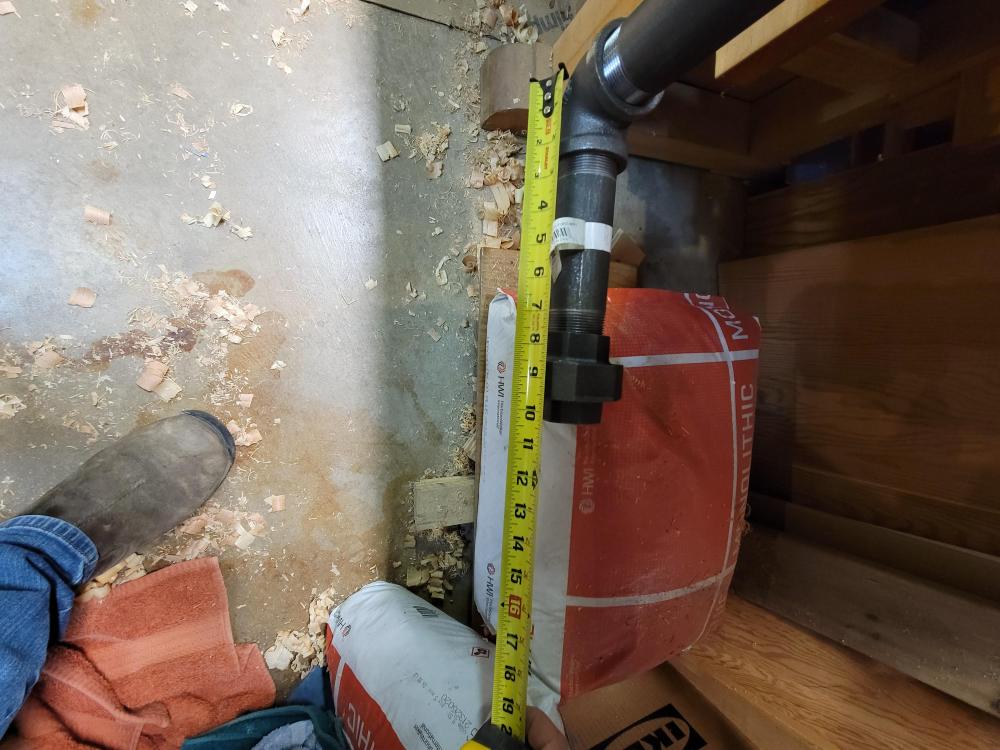
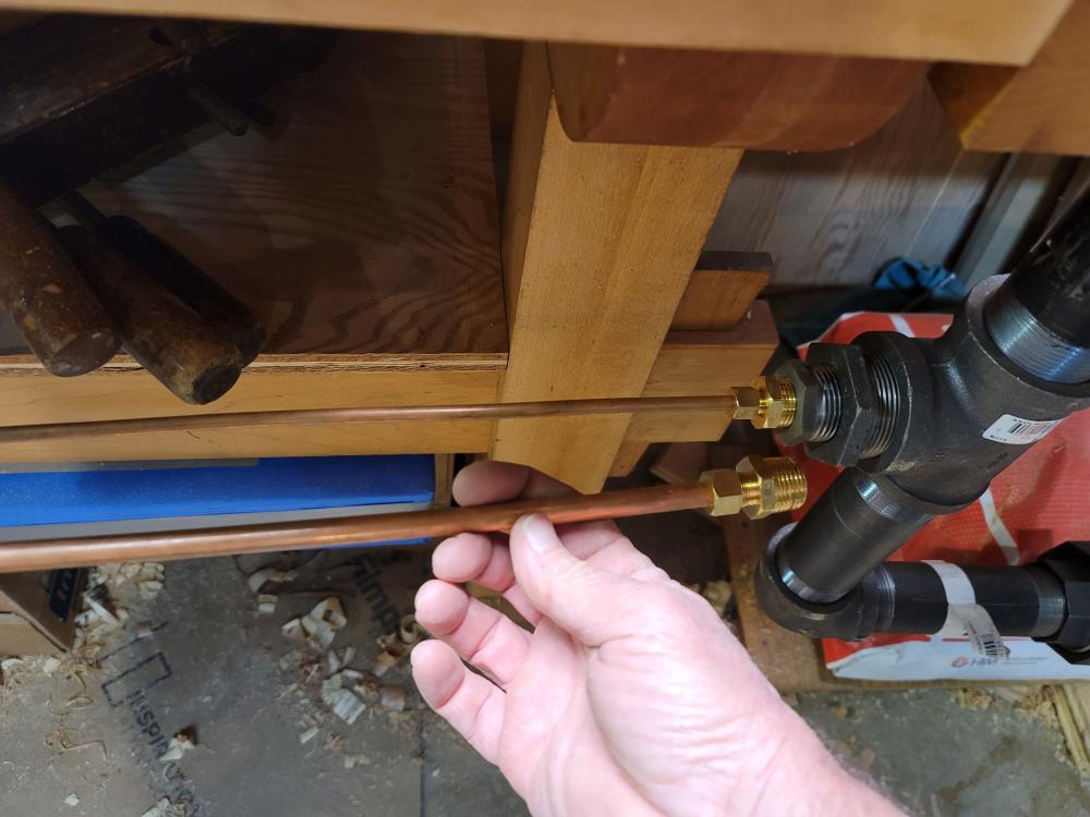
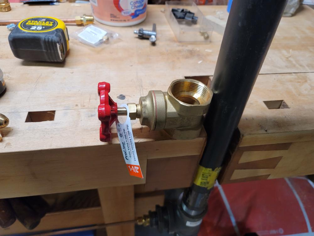
PI have been building a new gas forge over the last several weeks. It included building a small 4" x 6" ribbon burner and casted refractory forge shell and forge burner base. It is a bottom fed burner table with a casted D-shape forge shell. The forge is not complete. Today I was able to fire it up just to test the burner and fuel supply. Next items to complete: 1: Coat the interior of the forge with Pilstix. 2: Add a layer of 1" ceramic board insulation to the casted forge shell. 3: Fabrication of a sheet metal shell enclosing the ceramic insulation. 4: Fabricate doors. I am attaching some pics and a video of the burner running. 20221112_131919.mp4 The forge internal dimensions are 12"w x 9-3/4"h x 15-1/2"d - Casted shell thickness approximately 2" -Casting material: HWI Versaflow 60 plus - Reflective coating Pilstix - to come. Forge burner table base is a three layer base consisting of: 2300 degree IFB 2-1/2" x 22" x 25" 1" ceramic board insulation 1/2" of casted refractory Versaflow 60 plus which is Flux resistant and has a 3000 degree heat limit. Air supply lines are 1-1/2" black iron pipe air/gas mixer is a 1-1/2" iron tee with a 1/8" iron pipe gas feed. Currently there is no gas jet installed in gas/air mixer. I have brass plugs that can be drilled to create a specific gas jet size. Propane metering valve and two stage gas welding regulator and 1-1/2" gate valve for air regulation. Blower is an old Hye Sung coal forge blower that I had from my old coal forge. It says it has a static pressure of 40 ounces. The burner is a 4" x 6" casted ribbon burner that Was welded from 12 GA sheet metal and then casted with 26 holes roughly 7/32" in diameter. The current state of the forge build, some of it temporary like the support rack for the blower and the PVC air/fuel line below forge. That was rigged up just for burner test. Here are a few things I came across while building. Originally I base planningbto have the blower mounted at floor level and feed Air/Fuel straight up into burner. Like this But it occured to me that this layout could potentially be a safety factor. Propane being heavier than air could in the case of a leak collect at the floor level and come in contact with the blower motor which is not explosion proof. Secondly it seemed counter intuitive to try to feed a heavier than air gas from below. The conventional thought on ribbon burners is that they run at low gas feed pressures. Another reason to come up with a top down fuel/air set-up. So I reconfigured it so the sequence of fuel air system are as follows. Blower set 12" above forge, will have heat protection shield if needed. Next is air gate valve followed by gas mixer followed by 54 inches of piping run from outflow of air mixer to burner face. Pipe run includes 3 - 90 degree elbows. A union fitting sits between air mixer and burner for easy disconnect of air/fuel feed. Now for some thoughts on the burner testing which was not scientific in any manner. Nor did include any testing or measuring. Just some observations: I get a fairly neutral blue flame but it seems a bit on the cold side (low heat output). 20221112_131919.mp4 If I push too much air the flames start to jump off burner face. I can add both fuel and air and maintain decent flames that are still married to the burner face. If I push the air and fuel to high I get the following. 20221112_132502.mp4 I am thinking one or more of the following are could be issues. The air/fuel supply is too small (maybe should be 2"). Although I did calculate the total burner port area and matched that to the air/fuel pipe area. They are very close to equal. The unjetted gas feed port in the mixer is preventing proper mixture ratios, fine gas control, or leading to poor mixing. Lastly the blower does not have sufficient static pressure. Forge heating: I don't have proper doors installed nor do I have the Pilstix coating applied and tye outer shell insulation completed. It's too early to say if the forge will heat properly. I may have built it with more thermal mass than what is ideal. I did not want to deal with friable ceramic insulation, desired a flux resistant interior and wanted to reduce heat transfer from forge to shop. Not sure if a met my goals we will see. CHEERS!


-
Perhaps the two of you should start a new topic to discuss the meaning of Orifice. Anyone else on this forum have any thoughts on a reasonable blower for a ribbon burner other than the meaning of or proper use of the word orifice?
-
Frosty, The air supply is not built out, I just cobbled a few items together to give you a general idea of the direction I was headed. Nothing is set in stone at thus point. The pics I attached of the piping did not come through the original post. I am heading back from my trip to look at the champion #50 blower. It blew air but had little to no resistance to back pressure. By no orifice (jet) some others were suggesting to directly pipe the propane into air fuel supply using a straight 1\4" pipe, no tiny hole orifices. I don't have the knowledge to say wether this is good bad or indifferent. originally I was planning to run copper pipe into the pipe tee center. crimp and solder the copper pipe end and drill a gas orifice hole somewhere between a #60 and #58 drill size. That would be my gas orifice. I am running into a brick wall regarding a proper blower for my ribbon burner. Research points to squirrel cage blowers no good, anything I can find the puts out an inch or so of wc pressure is insanely expensive. I am kind of at a dead end with this. Rick

-
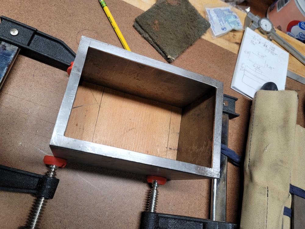
Thank you Frosty, I got a bit more information on the blower. Impeller diamater is 10" estimated rpm on motor is 1500, HP is a bit sketchy, maybe 1\2 hp. I will be making a trip to look at and run a static pressure test on the blower. Yes, Frosty I incorporated a vadfel plate in the burner plenum. I basically followed what I could dig up on the Pine ridge burner. I am attaching a few pics of the burner plenum build out prior to welding on the top cap. As for the piping and gas connection. That's a bit up in the air as I don't have a blower yet so I took a few pics of what I am thinking. I incorporated your suggestions on length and elbow addition to help in fuel/air mixing. I have read few maker suggestions that imply there is no need to install an orifice. so direct pipe in of Gas to fuel/air supply is sufficient. An in-line needle valve acts as the orifice. I'm sure I will need different nipple pipe section lengths once I have blower in hand. Any Thoughts?


-
Latticino, Thank you, I am not expecting anyone to run an analysis. the burner will be bottom mounted in a raised forge platform. This particular blower is direct drive and could be mounted so that I end up with straight piping from blower outlet to burner input. Blower output is 3" round, air supply piping is 1-1\2" black pipe. IdeallybIbwill end up with 16-18" of pipe, no elbows, a gate valve and a reducer from 3" to 1-1\2". I have asked for motor specs but motor plaque only states volts, cycles and tye number 50 in the box preeceeding the cycle figure. My guess is that it's 1/2 hp. I will run a static pressure test on it with a u tube manometer to get a better idea the pressure it puts out. A 5 hour round trip drive to see if something may work is something I am trying to avoid. Rick
-
hi everyone, I have a chance to pick up a working Champion #50 blower with motor. what I am wondering is if anyone has an idea if this blower will meet the static pressure needs of a 4" x 6" ribbon burner. any guesses on how much static pressure this blower will produce? obviously we are assuming tye blower is functional and sound thanks for your insights.


-
Thank you Frosty and No Good With Usernames (NGWU) for the insights. I like the downward moving ram, it just seems proper and intuitive to how one works and being able to see how your moving the metal. i may be over thinking it but its just very odd to me. Frosty does the plan for the 24 ton press call for using the W14x38 H beam as the main pedestal support becuse of the larger ram, higher pump and pressures to resist twisting, or is it just a different design concept to acommodate downward versus upward piston movement? The book includes force and safety ratings for beam and structural members alobg with ram cylinder pressurs as a guide. With prooer application of the information it looks like one could make some modifications and maintain safe limits. Thank you, Rick
-
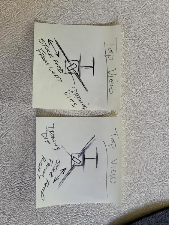
Thank you Frosty for the quick reply. Frosty if I understand what your saying here, the die mounting plates can be angled so stock can be run as shown in the attached drawing? I dont get what you mean by lengthening to the left and widening to the right? Isn't that simply a preference or work requirement of feeding from left or right into a drawing die to lengthen out stock? Wouldn't widening stock be a cross peen orientation die to stock? Maybe your refrrencing some type of multifunction die plate that I am no following or understanding. Rick
-
Good morning all, I would like to build a Forge press, through the iForge Iron forum I learned about James' book, which I purchased and have been going through. On my second pass through the book I realized there are two different forge press designs. One appears to be a smaller 20 ton H frame press with tye cylinder ram mounted at bottom with an upward traveling piston. The second design with mechanical drawings at back of book are of a 24 ton presss that appears to be something other than an H frame design. It looks more like a single pedestal in which the ram and anvil block mount and slide on the face of the Large H beam flange. This appears to create a press that one feeds material into the anvil dies from the left and or right side of the press when looking straight onto the press. The smaller 20 ton H frame press allows material to be passed through the anvil dies from the front of the press. My questions are: Has anyone built or used each of these designs and what are your thoughts on working with each type? I like the concept of the smaller H Fame but do not like tye bottom mounted and upward moving ram piston. I am used to a 50# Little Giant. The upward moving anvil orientation seems as it would be problematic and a bit disorienting while forging. The 24 ton Pedestal design is more akin to what I am use to except form limitation of being able to rum material straight into the dies. This makes it seam a bit awkward to feed and control ram motion from the side. also not sure if a foot mounted control similar to a traditional power hammer control foot bar could be fashioned. My next question, Has seen or modified the 20 ton H frame to position the ram at the top inorder to have a downward operating piston and anvil? I will have a welding fabrication shop weld up the frame parts. I am looking for input on the different designs and the modifications needed to reverse piston motion on the 20 to H frame press. Thank you, Rick
-
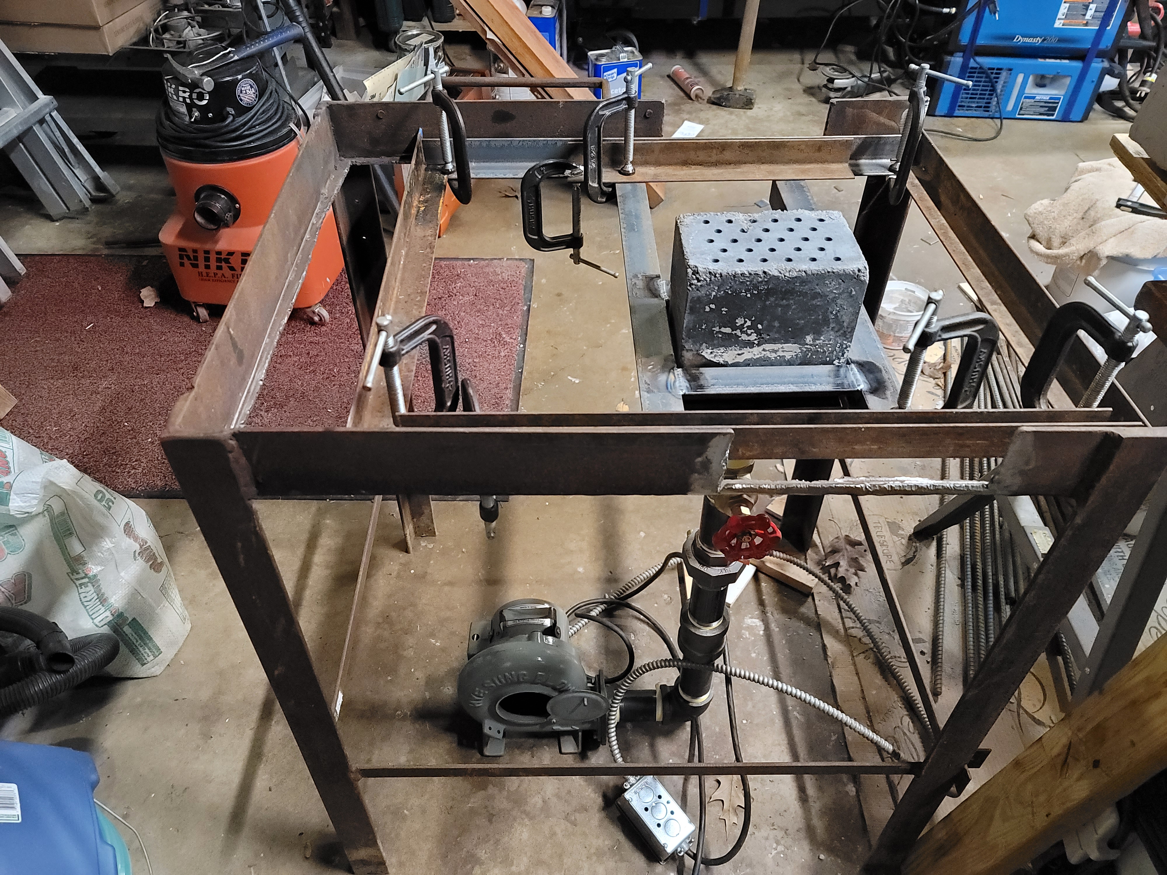
Good morning all, I àm a new poster and long time reader of the forum. I live in Cedarburg, WI which is about 30 minutes North of Milwaukee. I have read most of the content in Forges 101 as well as the burner and ribbon burner sections. I am converting from a coal forge to a propane blown ribbon burner set into floor of an insulated fire brick and castable refractory base. I have included pictures of the forge stand and base form with IFB brick inlay and box out for burner placement. I have also included pics of the Forge casting form and 4-1/4" X 6-1/4" ribbon burner based off the Pine Ridge burner. The plan is to pour a 1" castable refractory layer on top of the 2300 degree IFB brick base. i need to know if tye IFB bricks need to be mortared or set into refractory mortar prior to pouring refractory layer. Second question is wether in need to insert refractory hangers or any rebar wire for the 1" castble floor. I am using versa flow 60 high alumina castable refractory and have 1" ceramic board as an secondary outer layer of insulation if needed. The forge casted shell will be 2" thick, followed by a 1" layer of ceramic board with a 16ga steel outer shell. The interior hot faces will be coated with Plistix. The door openings of the forge will be offset to right side allowing the burner placement to be far left hoping to create a nice flame circulation, retention of flame heat, and minimize flame impingement to the forge as well as the work pieces. Thank you for your consideration and and thank you to everyone who has taken the time to post all your insight and knowledge on the forum. Rick