

G-son
-
Posts
119 -
Joined
-
Last visited
Content Type
Profiles
Forums
Articles
Gallery
Downloads
Events
Posts posted by G-son
-
-
Had to search for the atlas burner to find info, didn't know about it. Appears to be an extremely simple design, and while I like simple things it's rarely the way to go if you want high efficiency. What you save on a simple burner may cost you a lot in gas consumption further down the road.
-
Would perhaps make more sense to talk about angles than diameter to length ratios.
-
The same thing goes for oxygen/acetylene welding torches. Turn the flame down too far and reflected heat can overheat the tip, causing backfiring inside it (and getting you sprayed with molten metal in the process).
-
That looks really good! Promising for a small (hand held) burner using one of the smaller nozzles.
-
These cooking burners use very thin metal and small holes, seems to work there. But I'd also worry about backfiring when the metal gets hot as it does in a forge. Might need a material that insulates better. or perhaps cooling the metal in one way or another, but removing heat from a forge seems counter productive.

-
Wasp waist DOES sound good, and mentioning the waist makes it pretty clear they have one. Sometimes being "more technically correct" doesn't help people understand what you mean, quite the opposite when you start using words most people don't use regularly and perhaps don't even know what they mean.
-
12 hours ago, Frosty said:
A couple points. No need for a flame retention nozzle, that feature came about as an attempt to stabilize burners that didn't have a full length tapered mixing tube.
So long as the mixing tube taper does NOT exceed 1:12 the flow will remain smooth more taper and turbulence will break it up and it won't work.
The air intake cone is typically much more obtuse on commercial versions.
Glad to see the experiment.
Frosty The Lucky.
Thankyou.
I added the nozzle as some of the commercial wasp waist burners flare out into a short nozzle. Others just end without anything after the cone. Easy enough to remove and see what happens.
I should be good on the taper. Good to know a number to aim under, for future versions.
The intake cone on many commercial versions seem to often be a smooth radiused bell mouth, starting at a steep angle (often ~90 degrees), progressively going down to basically zero angle at the waist. As I have a "straight" cone, the steeper the angle, the more sudden change of direction at the waist. I wanted to keep the sudden change at the waist relatively small, especially as I have no "rounding off" between the cones = there's a sharp step there (and from what I know of aerodynamics big sharp steps are generally good to avoid). Could get both a steep angle entry and small angle change at the waist by making a multi-stage cone, two or three different angles from the start to the waist, but I think that belongs somewhere later in the testing procedures - when most of the pieces aren't held together with just wire and tape. -
Out of the history of all cobbled together xxxx this might be the worst… but as it actually worked as a prototype and can be a useful method for someone else who perhaps want to do it a bit more seriously I'll show it here.
I got interested in the wasp waists the last few days, and threw together a very, VERY basic prototype. It's simply two sheet metal cones and a flame retention nozzle. Metal comes from old shaving foam spray cans - costs nothing and is very easy to work with, good enough for a quick n dirty prototype. I didn't bother trying to go for a specific length to diameter ratio anywhere, as my thinking is that I grind the small end off the cones shorter until the waist is large enough to produce a neutral flame - changing the diameter and length at the same time, so it's basically only good for finding the approximate waist diameter to go with the 0.6mm MIG tip I'm borrowing from my previous build (that has a 18mm mixing tube, yellow on the second picture, the prototype waist is 12mm for starters). The entry cone has the same angle as on the linear burner (that's 3x mix tube diameter att the entry and 4x diameter length, but in this case, as I said, I more or less ignored everything but the angle), and the exit cone opens up at 2 degrees from center line, 4 degrees included angle.
Testing conditions weren't ideal, couldn't see the flame well outside in daylight so I can't really say much about the waist size vs. tip size now - need to work on that in less light. But so far: It burns most stable with the gas turned up relatively high, and the gas jet needs to be rather far back from the waist, going closer causes fluttering. I held steel wire in the flame and it goes bright orange (same for the 18mm burner), but the hottest zone of the flame is closer to the burner.
It's far from a functional burner, but it's interesting that it burns as well as it does with the gas jet out of a burner with 50% larger mixing tube diameter = 2.25 times the size of the opening. My testing is probably shut down for winter soon, but this seems like a concept worth diving deeper into later. And anyone else can make the same kind of cones, thicker sheet metal just requires a round bar to work it around and a mallet to shape it with.

-
32 minutes ago, D.Rotblatt said:
Now here's the question....is this then a 1" burner, or a 3/4" burner?
Very excited to see those results!
About sizes… 1" burners and 3/4" burners have nothing to do with 1 or 3/4 inches, other than the tubing they're made of is graded by a system that once upon a time had that size, before it was changed to thinner wall thus increasing the internal diameter. I'd say scrap the incorrect grading and call it what it actually is. As it has (at least) two diameters of interest, it would make sense to call it a 0.75/1.00" burner, if those are the actual diameters of the waist and exit. You can even take one step further and grade them in metric, reducing the risk of confusion. Out with the old, in with the new.")
In the end, the diameters don't really matter. The important thing is how much heat they put out, i.e. how big forge they can handle, if they are to be used in a forge. -
8 hours ago, Mikey98118 said:
So, are they good or bad as compared to recent homemade burner designs? The result will, as always, depend on how well they are built.
No doubt. But what potential do they have? Are they worth messing with? There's plenty of proven designs for "straight tube" home built burners, is there so much room for improvement* over them so the extra work involved in waists is worth doing?
*: Improvement = Changes like hotter, more efficient, or giving different flame characteristics more suitable for some specific jobs. -
9 hours ago, Frosty said:
A good enough plumbing pipe burner is really cheap and doesn't require special tooling so if folks will buy them a maker would have to be a fool to try selling high performance "Wasp wasted" ones. Hmmmm?
To answer your second question. YES a mixing tube tapered in the below manner makes a significantly more effective burner.
The desire for a lathe just keeps getting stronger, and the parts casting we see here may be an other way to some really potent home built wasp waist (or new style) burners. The future will be interesting.
I would think that there's always people who want to buy (or build) the cheap & "good enough" equipment, and a few that want the best possible, even if it costs quite a bit more. Higher performance has also always been a good selling point. But sure, at a suitably higher price to match the higher manufacturing cost the wasp burners probably wouldn't sell in very large numbers, and many would perhaps not bother to develop and make them just to sell a few.
The gas jet size will have to be quite a bit bigger in a waist style burner than a straight tube burner of the same diameter, to match a larger amount of air, right? Or to flip it around, you need a smaller waist to the same size gas jet.
I'm thinking I may have to roll some sheet metal cones, for waisted burner tests… Hmm. -
4 hours ago, Frosty said:
Old style tapered burners have significantly stronger induction.
What design are you referring to? I haven't had the opportunity to look closely at very many large commercially built burners. I assume there has been many designs around, many perhaps more because of easy/cheap construction than best performance.
And, are you saying that ditching the straight tube for other shapes can be a big step up in performance/efficiency? Or is it one of those cases where you get one improvement at the price of loosing something else? -
38 minutes ago, Another FrankenBurner said:
It sounds like we are going to 3 vanes for vG2 and possibly taller vanes for vG3.
One thing I can say about this version, the radiant energy felt on my face while standing near this thing is much higher than the versions concentrating the flame forward. It makes me wonder how the vortex flame will act inside a forge.
Sounds like suitable development.
That also makes me wonder how the vortex flame would work for general heating outside a forge too, as in hand held burners and similar equipment. Granted, you wouldn't want the heat to radiate away to the sides where you're not heating something, but you'd also not want too much of the heat to "blow away" with the moving flame as it has gone past what you try to heat.
You could try setting metal wires through the flame at different distances from the burner, perhaps at ½" steps. Not extremely accurate, but the glowing color of the wires would give an idea about how hot the flame is, or how hot different areas of the flame is. It's a simple test that has shown me what area of the flame on my (bought) hand held burner to use, there seems to be a lot of temperature difference between different areas. -
Well, there's a lot of rotation visible in that photo, really interesting! A short and wide flame could be useful sometimes - if the performance in other ways is good enough of course.
-
3 hours ago, bertie_bassett said:
G-son - i expect ill end up using the lathe and mill to machine such a small burner from solid, much easier to maintain concentricity. the nozzles should save on trying to drill tiny holes.
It does indeed seem quicker and easier to make parts as you want them, rather than searching for parts and pieces that already has the more or less correct dimensions etc, at least when you have the machinery to do the job. Getting the pieces lined up straight "automatically" is a huge bonus.
You also get the option to make small changes in, say, mixing tube diameter, so you can tune the burner towards a neutral flame with the available nozzle sizes - rather than shortening or enlarging MIG tip openings with O/A welder tip cleaners, as can be done to adjust gas flow from the tips used in larger burners. Seems a bit more repeatable, if you were to build a number of identical burners - you make one prototype to find the dimensions to get it tuned right, and then just make identical copies that should work just like the first one. -
54 minutes ago, bertie_bassett said:
im hoping that the smaller options will allow for a small but very hot hand torch, somthing for heating up small localised spots for brazing or just heating up bars for twisting. wont be as hot as an oxy rig but might get hot enough for most tasks?
ill have to let everyone else design and test things though, i dont know anywhere near enough to make a decent start.
You will indeed not get near the same temperature with a fuel/air flame as a fuel/oxygen flame, but often you don't really need the high temperature when using a hand held torch, rather the high energy output. A oxygen/acetylene flame can easily heat a small point to and far beyond the melting point of steel, which is excellent when you want to weld.
For bronze brazing or heat treating steel you often want the heat spread over a bit larger area (as fuel/air flames do, they can't be as focused), and you only need to heat the metal about half as hot as for welding, quite a bit less than that for silver brazing. So, you are fine with a "cooler" and wider flame most of the time, as long as the energy output is large enough to bring the metal up to a suitable temperature fast enough, and you don't have a problem with heat spreading to other near by areas you don't want hot. But sure, high temperatures are good, just not absolutely necessary most of the time.
I have a store bought hand held burner, using the disposable gas canisters, filled mostly with butane. Impressive for what it is, great for small silver brazing projects and has done a lot of general heating for various garage projects. Unfortunately it can just barley melt bronze brazing rod under ideal conditions, it's too small to keep up with heat escaping from the metal. The burner mixing tube is 5mm (for comparing it with other burners).
My first burner build has been a 18mm (a bit bigger than ½" pipe) linear burner with the smallest MIG tip, just because MIG tips are easy to get, and it's fed from the same kind of gas canister as above. Works great, but just as predicted the small canister just can't keep up for more than a couple of minutes at max power. That has been enough for projects like heat treating a home made jaw for a broken sheet metal shear so far, so not bad all things considered, but not really good either. (Getting bigger and better things for that one... eventually. Along with a forge.)
Now that I know I can build working burners, and that it's pretty fun doing it, I'm planning for a more sensibly sized hand held burner - something around 10mm, which will probably give around 4x the energy output of the store bought one (or so I'm guessing). A good increase, but not insanely large compared to what the gas can is supposed to be able to feed. Will probably still get a limited working time at full power before the can is too cold, but assuming it's something like 8 minutes or more (rather than 2) it's quite acceptable. Most projects for such a burner is done in a few minutes anyway, and the ones that take the most time are the ones that would benefit most from a bigger burner.
With these 3D printer nozzles there are sizes that should work for such small burners, so that makes that part of the build much simpler & cheaper. Too bad lining up all the parts gets harder instead when you build smaller things. Trying to get my hands on a small lathe to help that part of the build, would make much of it so much simpler and quicker (and cheaper). Anyway, the garage is becoming too cold now anyway, so most projects are on ice until spring. Time to search for a lathe, plan the build, and perhaps see other peoples builds using the nozzles. -
2 hours ago, Another FrankenBurner said:
I usually get into the problem areas when reality doesn't match up with what the book says so then I have to question what I am told.
How about this guy:
Or would you like to take Mikey's suggestion of dropping to 3 vanes?
When the reality doesn't match how things are supposed to be you can generally be sure there is SOME kind of problem going on.
Human error may be the most common kind, and not all humans like to admit they were wrong. 
The picture is perfect for what I had in mind, I really like it. At the same time, Mikey generally has a good idea what he's talking about. Probably best to go with the three vanes. -
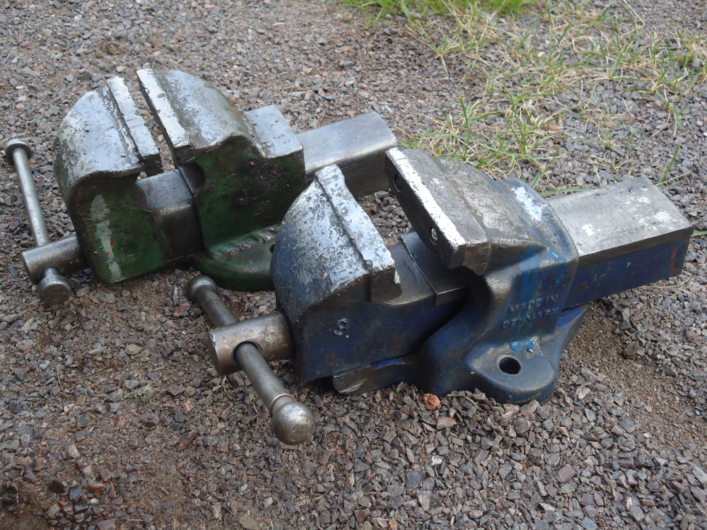
Brought these two home yesterday, about $5 for the green one and $10 for the blue. Both are 4" wide, the green opens about 5", the blue 6".
The green one has no markings and is made mostly of 5mm thick sheet metal welded together, and judging by the amount of weld spatter etc. it may have been on a welding table or just been someones go to place for welding. Not really impressive in any way, but it seems to do the job a vise is supposed to do.
The blue one is marked 3 and Made in Denmark, and appears to be made from cast iron. Descent shape, apart from missing a jaw, a piece of cast iron is broken off under the other jaw, and some weld spatter that has been ground off now. Was suprised to see that the jaws were attached with 1/4" screws, and those don't exactly grow on trees here, at least not if you want a specific head. Anyway, one of the threads for the missing jaw appears rather damaged, so when I've made a new jaw I'll probably helicoil them to M6 instead.
-
1 hour ago, Another FrankenBurner said:
Yes, we have all dealt with that guy. For me that usually means I am talking to an engineer. That is not an expert thing, that's a personality thing. They know too much to be bothered with questions. I have met a few actual experts. They were truly experts in whatever field and knew nothing of anything else. The ones I dealt with were nice and didn't mind being peppered with questions. My relentless curiosity in everything means I will never be an expert in anything. I'm ok with that. I suppose learning is my passion. The more I learn, the less I know.
Here is a start, version G1:
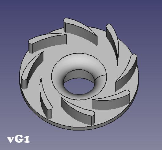
It's my guess at what you were thinking. Anything you want changed? Taller vanes, different shape to the vanes, larger OD, larger reduction radius? If you have a different idea, I can work with hand drawings.
I have yet to meet one of those engineers, the one I've talked to didn't have that habit. Although that was back when he was studying and some time after, it's been a few years so things may have changed.
The "jack off all trades" tend to be interesting to talk to. Lots of insight into many areas.
The drawing is close to what I'm thinking. A little longer vanes to increase overlap, and a bit taller vanes to increase inlet area past the vanes to reduce the risk of restricting the flow there, and it's perfect! (Or, so I hope. If it fails I can call it a perfect failure, I'm not picky. )
-
9 hours ago, Another FrankenBurner said:
I am not trying to poopoo your idea. I like ideas. I will CAD it up and we will see.
I've been involved in some online discussions with experts in the discussed field (engine tuning), where one expert often just replies "That doesn't work!", and when anyone tries to ask about more details not he gets xxxxxx off and suggest anyone doubting what he said to try for themselves (which would require some expensive equipment that normal people don't have access to).
You give great answers, with your reasoning very clear, no matter if you agree or not there's something to learn and new knowledge to base future ideas and theories on. The answers from the so called tuning expert I mentioned were on the other hand rather useless, I'm sure he was right about that specific case, but not knowing any of the logic behind it it's impossible to try to apply that to any other slightly different situation. Constructive criticism is great, even if the idea turns out to be useless. -
You have some interesting points. Would be very interesting to see an actual test.
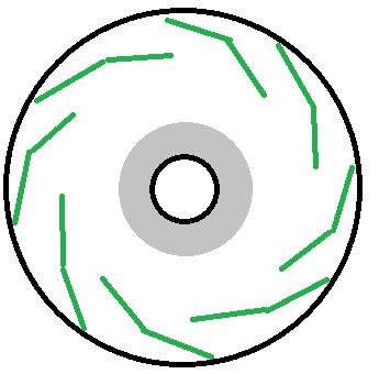
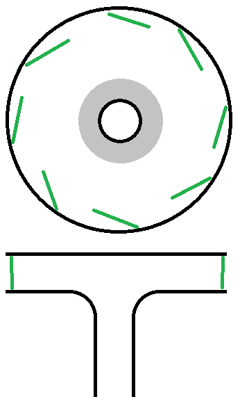
These vanes is more along the lines of what I was thinking, with overlap so the air must go diagonally between them - the large total area of the openings compared to the mixing tube should still mean there's little restriction to flow. Once it's moving that way, it's easier for it to keep rotating than to change direction straighter towards the center - or that's my theory anyway.
I can't quite tell what OD would seem right, but say something like 2x funnel diameter to the inside of the vanes, and then let the vanes have as much size as they need at an angle that looks good and gives them enough overlap to direct the air around, preventing the air from going straight towards the center. In this picture it looks like 3x funnel diameter may be good for outside diameter, but better drawn in a more aerodynamic shape that might change a lot.
-
Tried anything along these lines? Starting with many vanes at a large diameter, probably overlapping each other to really force the air to follow their angle - even if the space between each vane is small the large number should let plenty of air in, and at fairly low speed. It starts rotating rather slow out by the vanes, as it goes closer to the center it rotates faster, and once going down the funnel it might just be a lot faster than in the small diameter versions. Or it might not.
-
Does indeed sound like a three phase item. Depending on how they're built they may or may not have a neutral. As said, much more info needed.
-
A few minutes with the wire brush in a drill and now it looks like this. Good enough for now.


Forges 101
in Gas Forges
Posted
Was this perhaps supposed to go in the "Burners 101" rather than "Forges 101"?
Anyway, as you say, a smaller burner may require more time to build to the required precision, material costs only go down a little (from using smaller/shorter pieces), and you still need to do the same number of machining operations, setting the pieces in the mill/lathe etc. the same number of times as when making a larger burner. As usual the big cost is the time spent, not the materials.