

Sanderson Iron
-
Posts
158 -
Joined
-
Last visited
Content Type
Profiles
Forums
Articles
Gallery
Downloads
Events
Posts posted by Sanderson Iron
-
-
1 hour ago, jumbojak said:
I'm curious about the shafts and belts themselves. From the photographs it appears to be a steel shaft fitted with wooden pulleys (some of them at least) run by leather belts. Were the shafts and pulleys fabricated or salvaged from another shop? Regarding the belts, what material do you use and what sort of service life can you expect from such an arrangement?
Jumbo, line shaft pulleys are (were) made in halves. They bolt together and grip the shaft without a key. The center of the pulley has an oversized hole (usually 3 7/16") so there can be an inserted hub put in them to fit different sized shafts. There were three pulley materials: wood, cast iron and steel. The steel is usually thin, pressed steel. Of the three, wooden pulley are the most common to find, but they also transfer the least power. This is mainly because they can grip the shaft only so tightly, because the wood crushes. They also change with humidity, so the grip loosens eventually. (Leather belts do too, so that's another reason to use rubber belts.) The inserts in wooden pulleys are usually wood, but the metal pulleys (cast and steel) usually were fitted with cast iron inserts machined to fit. These grip well. I've made inserts out of wood, steel and PVC. For any heavy load or a load that'll be shocking (like a hammer) I use steel inserts bored a few thousandths under shaft size. These are cut in half and then, in two places, cut nearly in two lengthwise to the bore so they can flex open and squeeze against the shaft to grip it. If I have to use a wooden pulley under heavy load, I at least put a metal insert in it.
The belts last a long time if they are not expected to bend and distort for some reason. My Murray is set at an angle to the shop, so the belt has to come down and angle around an idler in order for it to track. This bends the belt and breaks it apart, so that machine is on its third belt now (since the early 90's). I really don't know how long a belt will last if it's set up right, because the first one I put up is still going strong.
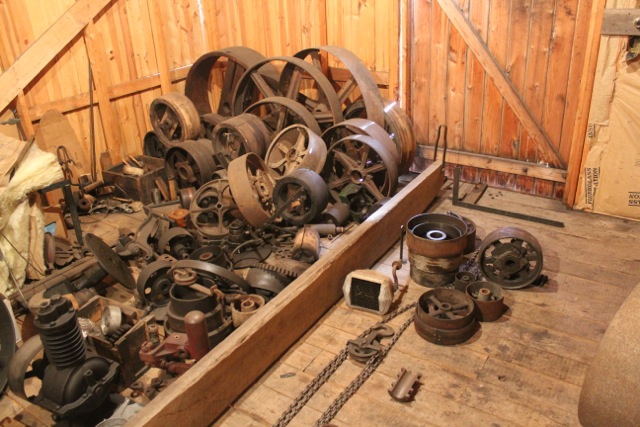
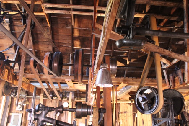
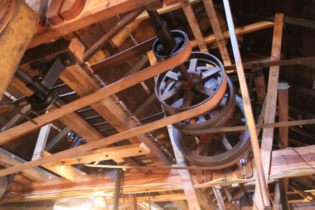
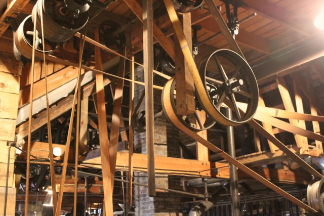
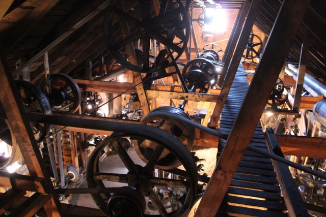
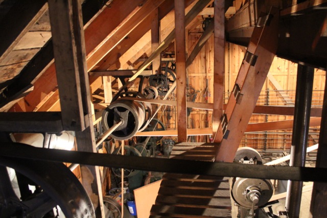
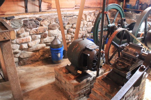
My pulleys and bearings have all been salvaged from old line shafts. I get them wherever I find them and keep a pile on hand for the next machine to come in. In the first picture below you can see my assortment upstairs. (The board in front of them is my outside crane. I open the door, slide the board out with a chain fall on the end of it and bolt it to the floor. It works great.) In the second picture you can see, on the right side, the angled belt coming down to the Murray. I wouldn't do that again. It's a lot simpler to mount things square, and it makes a lot less headache.
joel
-
1 hour ago, Kevin_Olson said:
1. Is the space insulated. 2. Being a line shaft rookie, are there clutches or some kind of disengament devices so that every shaft doesn't turn all the time.
The insulation in the shop is not the best. I keep at it little by little. When the emerald ash borer first hit around here, we cut a lot of ash trees, and I used those on the walls of half the shop, insulating behind with R13. I need to cut more trees for more boards and keep going with it. Thing is, that really's only for a few months of the year. The engine room is very well insulated, but I don't work in there.
I cannot turn the line shafts off. The individual machines each have a clutch, either on the countershaft or on the machine. As a rule, if the machine has a clutch built into it, I use that instead of adding another clutch on the countershaft. For example, any power hammer with a clutch is meant to have its pulley turn all the time, so why complicate things and add another bearing to have to grease and another clutch to have to adjust? When I first put the 250 pounder in the shop, I had a separate clutch on its countershaft, but it simply didn't last. A hammer can add a lot of shock to the system when you suddenly step on the pedal and expect it to respond. Now the Murray's idler runs all the time the engine runs. It's just a bearing and is no harder to replace than any other bearing in another clutch.
Speaking of the Murray: starting in 1998, for seven years I relocated my business to Ohio in a shop without a line shaft, and I ran the hammer with an electric motor. It was a huge old three phase thing, 7 1/2 horse power, with a 4 groove V-belt pulley going down to a jackshaft and then up to the hammer's pulley with a flat belt. The motor was bolted down with four fine thread, grade 8, 1/2" bolts. During the years the motor drove that hammer, I broke two of the bolts, I broke a foot off the motor, and I slipped the Browning taper lock that held the 4 groove pulley! Motor systems are just weak--and that was a big motor! When I brought it home to the line shaft, I added a 30" cast iron pulley to the end of the countershaft to act as a flywheel, and I drive the shaft through that with a 6" belt carrying 14 horse power. It's happy now. The mass of the pulleys and the power of the flat belts works much better than the motor did.
Tillers is just a bit over an hour west of me, Tony. If you're coming up from Virginia, you'd be within six miles of my shop if you come into Michigan on 127. By all means drop in. Give me a holler and I'll give you directions.
-
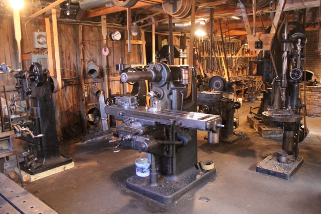
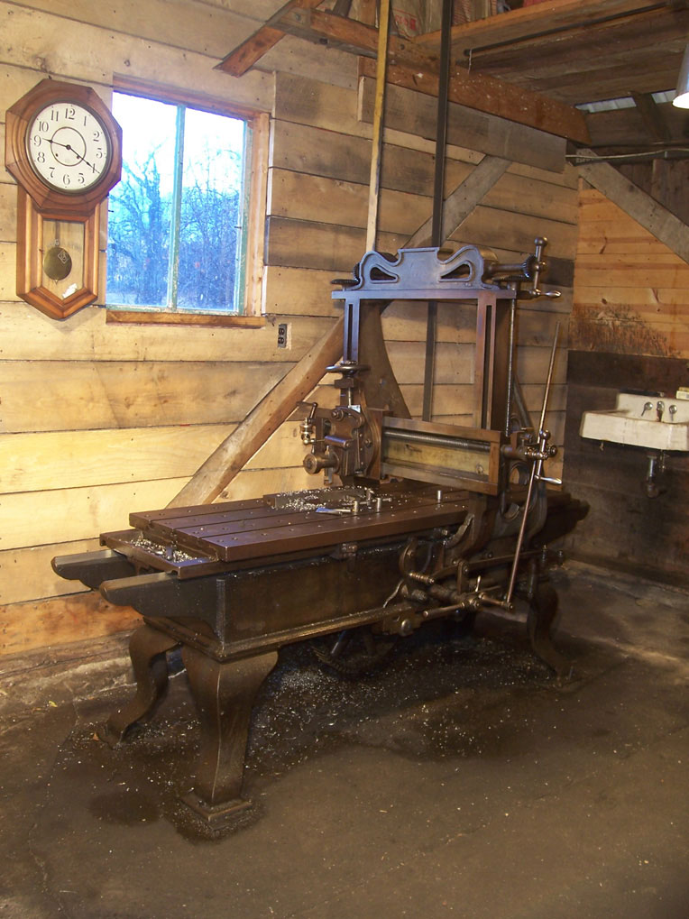
Here are pictures of the machine tools which I mentioned in an earlier post. As I said, each was selected to have a purpose in the shop--primarily to support the forging, making dies and so on. You can see there isn't much belt issue down low where you work.
The oldest machine in the shop is the planer, made in 1869. I've heard of one other like it in the Henry Ford Museum in Dearborn, but mine's still making a living at 147 years old. I bought the lathe from an old gentlemen at Tip City, when Quadstate was still there, who said his father bought it used in 1910, and he guessed it was from the 1890's. Both of these machines are more accurate than I can measure, doing half thou work consistently. The horizontal mill is dated 1911. The surface grinder and vertical Becker mill both are from about 1910 or so. The drill presses are in that neighborhood too. I'm not sure when the Garvin die slotter was made, but I'd guess around 1920.
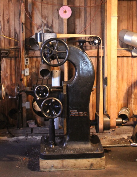
One thing to note is the way the Becker is driven. You'll notice there is a three step pulley, making three speeds. Overhead however, there is a double clutch, which most people associate with a lathe for forward and reverse. However, I'm running each clutch with a different size pulley, making a high and low range, for six speeds. These speeds range from about 400 rpm to 2500 rpm. It's a great little mill. Again, this isn't my invention. If you look on page 60 in Kenneth Cope's planer and shaper book, there are two engravings of Flather shapers with double clutch assemblies. There is no reason to run a shaper in reverse, so this could only have been for different speeds.
The last picture shows the two sized drive pulleys going to the Becker.


-
To put the engine's consumption in perspective, if you have a pickup that gets 20 miles per gallon, and you're driving 60 miles an hour, you're burning three gallons an hour just to go somewhere. Burning a third to half that is pretty decent considering all it's doing for me. I could have put in another engine which would have been more economical, but I wanted a low RPM engine in order to be close to the line's speed. 1:1 is the best ratio for power transmission with flat belts. If you follow the belts from the engine to the main power draw--the 250 pound hammer--it's nearly 1:1 the whole way there, because the hammer runs about the same speed as the engine. This was very deliberate, but it required a low rpm engine to do it. The Reid is rated to run 165 RPM. I run it 185.
-
8 minutes ago, CMS3900 said:
I had just found the walk-through of your shop on you tube the other day. Amazingly beautiful.
If I ever follow through and build another building to move my forging equipment in, I plan on it being line shafted.
What is the backup make and break that you have next to the Reid? Could you tell us about the journey of acquiring all the equipment, line shafting and electrical system?
How much fuel does the Reid burn in a month?
On a side note, who is your supplier for all that nice flat belt?
Thanks for sharing, it really is one cool shop.
Both engines are throttle governed. The smaller one is a Fairbanks Morse Z. It isn't belted to the shop yet. I've had it for four years and still haven't set it up. It's kinda hard for me to spend the time on something if a system is already working. The reason I bought it was for backup, quick starts and for lighter loads.
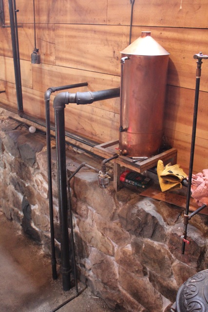
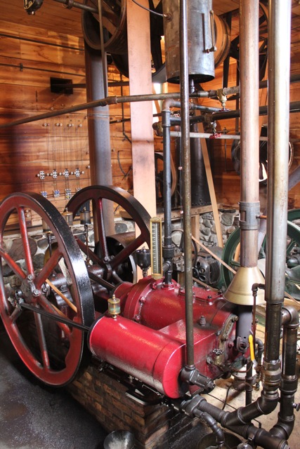
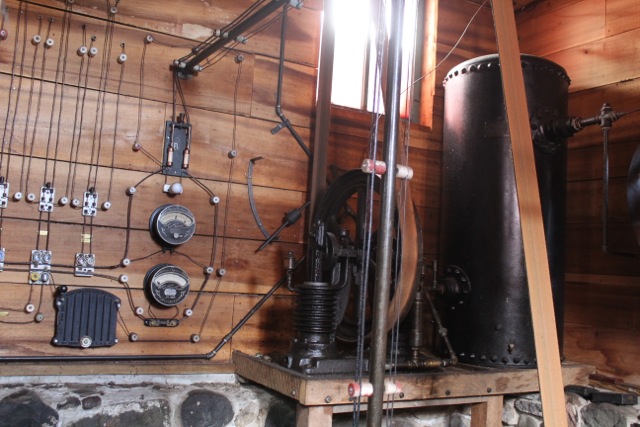
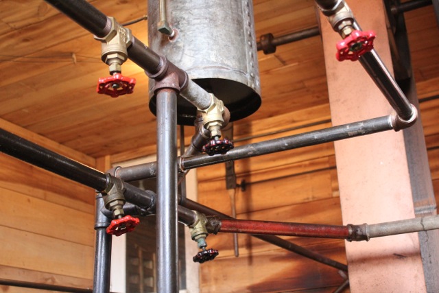
The Reid uses between .9 and 1.5 gallons an hour, depending on the load it's pulling, the time of year and so on. I have a copper tank on the wall with a sight tube that's marked in pints, so I can tell pretty accurately how much fuel I'm burning. I'm attaching a picture. In it you can see two black pipes coming into the building and going down to the floor. These are propane lines--the smaller one feeds the ignition of the engine, the larger feeds the cylinder. I start the engine on propane, and after it's warmed up (15 minutes or so) I switch to liquid fuel. I made the carburetor for it, which I wrote about in Gas Engine Magazine a few years back. The fuel I'm burning is a mixture of gasoline and kerosene. I can also mix diesel fuel with gasoline, but it's more finicky.
The belts are SBR flat rubber belts from McMaster Carr. Other suppliers handle them too, like Hit and MIss Enterprises in Ohio. I strongly recommend using new belts when you set up a machine. Old belts are not sticky, they are stretched out, and they don't pull a load. I buy four and five ply belts. They make them thinner, but don't get them if you plan to run any load through it.
There are something on the order of 28 machines run by the line, but I'd have to list them all to know for sure. I plan to show them as this goes along. Basically, the reason I went with a line shaft was because I wanted to (main reason) and because the shop has very weak electrical power to it (legitimate reason) which would have required I bring in a commercial line from who knows where. The shop's on a gravel road in the country at the end of the power line, and the power goes out all the time there. I like being independent anyway. Besides, like I said at the start, these old machines were meant to be run this way, and this is how they run the best.
Joel
-
Thank you everyone. I'm not trying to show off the shop here but instead would like to encourage anyone who is considering a line shaft. I think spreading knowledge is the point of this forum, and I think this is very relevant. Maybe I have something to contribute in this regard, but it's not like I invented this or anything. This is how our nation, the US, was built. It's a shame so much has been lost regarding belt transmission.
The first line shaft in the shop drives the machines requiring the most power: the three power hammers and the large grinder (as well as other machines). It also drives two other line shafts. There are 92 feet of line shaft in the shop, plus many, many countershafts. I have no idea how many feet of belt is used.
The second shaft after the first shaft is the main line, and it drives the machining area. It has the most machines on it. All the machines here were chosen specifically to make dies or to support the forging in some way. There is a 19" Economic lathe, a universal, horizontal mill by H.A. Stocker, a vertical Becker mill, a Garvin die slotter, a Planer, an 8" X 12" surface grinder, two drill presses, a pedestal grinder and a universal pedestal grinder. Using these machines, I can hold to half a thousandth, which is perfectly adequate for the dies I make.
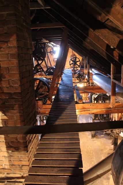
There is a catwalk along the center of the shop to service the main line.
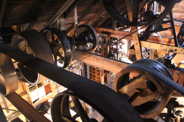
The first picture shows the east end of the first line. It looks like a real jumble of belts, which it is, but when you're working, its all over your head where you don't notice it. In the last picture you can see the main drive coming in through the wall to the larger pulley on the left; the belt coming across the bottom drives the main line to the machine tools at the west end of the shop.

-
Line Shaft Shop Tour
There is a lot of interest in line shafts among blacksmiths, and since I am a full time blacksmith in a line driven shop, I have decided to give a tour. Many of the machines we use in this profession were meant to be run from a line shaft, and I sincerely believe that is the best way to run them. Every blacksmith really should consider a line shaft, and I hope this will be encouragement. I will be happy to answer any questions anyone has about a line shaft, the way I have things running or about my shop in general.
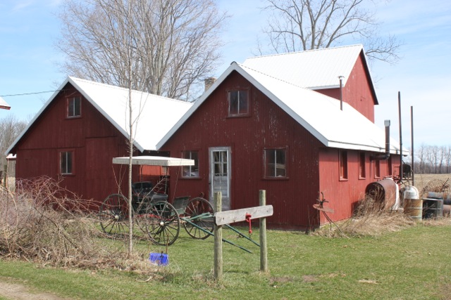
My shop is two buildings: the workspace, which I began using in the mid 1980's and is now two floors; and the engine house, which I added in 2004 and includes the office and show area. The workspace is divided into four areas: the machining area, the forging area, the assembly and stock area, and the upstairs which is for small work and storage. I intend to show each of these areas over the next few days.
Since the entire shop is dependent on the engine, I will start with the engine house. I built this as a separate building to keep the engine's noise and fumes out of the shop. (Up until then, I had an engine at one end of the shop.) There is a short hallway connecting the two buildings. The engine that now drives the shop is 118 years old; it is a Reid Type A, made in 1898. It provides almost everything the shop needs: the power to the machines, electricity for the lights and outlets, and even the heat for the shop. The only things it cannot power are my welders and the blower on my gas forges. In cold weather, the engine pumps its coolant through radiators throughout the shop for heat (and to cool the engine), and it pumps it through an outdoor system in the summer. I merely open one set of valves and close another to switch cooling systems. There are nearly 400 gallons in the system, but I got the antifreeze for free from a junkyard.
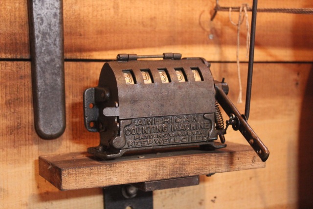
Also in the engine room is the air compressor, the dynamo, an exhaust blower so gasses are blown outside, a counter so I can keep track of the line's hours for servicing, and the fan for the engine's summer cooling system. All are run by the line shaft in the engine room. The air compressor comes on and off on its own, by air signals, or it can be controlled manually. (The control system is my invention.) The dynamo is a 110 volt, 31 amp Higgs Dynamo made in England in 1925. It generates the electricity for the lights, the outlets for my hand tools (Dewalt is still AC/DC) and for the magnetic chuck on the surface grinder. The pulley that drives the dynamo is 52"--big enough I had to cut a hole in the ceiling. The large drive pulley was necessary to get the speed correct for the dynamo.
By using the engine for all of my machines, my lights and my heat, I get a lot more out of a gallon of fuel than I would running it just for the machines. The first month I had my dynamo running, my electric bill was just $5.00. That's pretty minimal for a full time shop. Using the engine for multiple tasks is key to a line shaft's efficiency.
It might interest some of you to follow me on Facebook. I post processes once in awhile, with shop pictures. I'm not sure what the link is, but just look up Joel Sanderson/Sanderson Iron and you'll find me. There are more machine pictures on my website too, along with descriptions and some links to videos of the machines running. My site is sandersoniron.com. I hope it's okay to post that here; I'm certainly not trying to sell anything to a bunch of hairy blacksmiths who can make their own stuff.
I'll try not to be so windy next time.


-
How happy! Makes me smile.
-
Harlow, did you get the Hawthorn? If you get into forging very far you might wish you had that 100 pound Little Giant too. Don't know what year it was made, but the late Little Giants are some of the best hammers ever made. It'd behave a lot different than the Hawthorn, and different means you can do different things, of course.
What happened to the pictures you said you'd bring us?
")
-
That is so sad. Unbelievable what has happened. Why, why, why? The work these machines can do would stagger most smiths in America today.
-
Okay, I get it now, Thomas. Thanks.
-
Thomas, I think I understood you to imply that a toggle press is more for thin metal than thick metal, but I may have interpreted your "worn shilling" sentence wrong. I've used mine for any thickness, from 16 gauge up to 2 inches thick. Just depends on what I'm doing. I showed pictures of embossing and sheering thin stuff because that's what the try press is for, which started this thread. I use my toggle press for lining, texturing (both sides simultaneously if I want to), off-setting, slitting holes in round, flat or any stock prior to drifting, bending, riveting and so on. However, you're right--that should be another thread. Maybe I'll start one.
Coining with a fly press sounds interesting, Jim, and the fifteenth century is back a ways. I don't see why the press and the hammer wouldn't have developed together. They're so obviously suited to similar things. I'm no historian though. Maybe someone here has pictures of old presses. Are there some shown in Diderot's? I know your not THAT old, Frosty, but it'd sure be nice if your sister does find some of your dad's shop that you could share.
Joel
-
In my statement I was referring to the late 19th century power hammers which are commonly available and are still in use today. Of course trip hammers predate these, but those are barely relevant to today's smith. My point was that although power hammers are accepted and pursued by blacksmiths, the toggle presses, which are equal in both an historical and a functional context, are overlooked and ignored. Ignorance or trend? Having watched other trends over the last 30 years, like the air hammer and the fly press, my guess is that it's both.
-
There you go, Jumbojack, the first picture above is an OBI. See how the whole machine can be rocked to different angles? The flywheel's on the side with a crank in the middle, instead of like mine which has the flywheel on the back and the crank on the end towards you.
Thanks for showing those, notownkid. It sure is a shame any were scrapped. Can you imagine if eight hammers had been scrapped? People's cries would still be echoing. Had those been power hammers, they'd have all sold no matter the condition, and folks would have been declaring that they "saved" them and so on and so forth. Unfortunately, hardly any blacksmiths know what one of these can do, which is a mystery to me, because they've been around for as long as hammers. (The one I use probably predates the Little Giant company.) Why there's a flypress movement and no toggle press movement, I just don't understand.
Joel
-
I sure do appreciate you posting all this, Mr. Stevens. A friend of mine needs a new forge, and I've been talking up a wooden one when I came upon your thread. It's been a great help. Thanks.
My great grandfather used a wooden forge. We have no pictures of it, unfortunately. That would have been around 1900 or so.
Joel Sanderson
-
6 hours ago, jumbojak said:
Ah, I hadn't thought of using it similarly to a broach. And rounding corners and radii with round files would be very handy. For some reason the thought of using a round file didn't cross my mind. Thank you again! You too Thomas. This is a machine I'll have to keep an eye out for. Most of the information I found referred to its obsolescence, at least in the tool and die industry, but I can think of a lot of uses for a machine like that.
Blacksmiths can't listen to other peoples' ideas about what's obsolete, or we'd have to throw out our power hammers, shapers and camel backs! Shucks, I'd be left with nothing but an anvil and a welder. Nope, scratch that--just a welder!
Do you have a picture of your filer, Jim? I'd love to see it.
-
The die filer is for the final cut on the die and punch (both internal and external). It's more of a hand machine, because you hold the work by hand and move it around the file, gently and carefully making your radii, corners and cutting edge, with your face close to it where you can see it. The table may be tilted too. This lets you file an angled cut, giving the relief for the punch to enter the die and for your part to pass through. You don't have to use round files, of course, so you're not limited to round internals like you are with a mill, where you can never machine an internal square, for example. There is another machine, called a die slotter, which is more or less an upright shaper, that can do square internals and also cut the relief, but it's still necessary to finish the cutting edge with the filer. It's not a machine that takes off much material.
I've never used my die filer for anything other than dies, but I suppose you could.
Sure, why not, Thomas? Seems like a person could easily hold a saw blade too and turn it into a scroll saw. Never have, but it's crossed my mind.
-
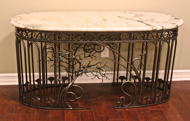
I can't give you any actual times off the top of my head. I'm a bit different than a production line. I make art, you see, ornamental ironwork, so I don't make parts to sell, but rather, parts for art to sell. The only way I can justify making the tooling and dies like this is to make parts which interact with each other, letting them be used in many different ways and combinations. For example, the 9-scrolls I showed on the back of the table above have the same curve as the sides of the fans; this lets the fans and scrolls be used side by side for a totally different appearance. On the other table, you can see that the C-scrolls share that curve as well, so they also can be used with the fans. I also have little arches which match that curve. The more the dies interact, the more the cost of making them is depreciated.
My wife works with me, but not every day, so when she comes in, I have things set up so that she can make parts efficiently. That efficiency, plus the multiple application of the parts, off-sets the time to make the dies. (I suppose that's pretty obvious.) Yes, it is very satisfying. It's really rewarding to me to think through a process--often one no one else has done--and then make it work well and see Jenny put it into action.
-
Yes, the screw press slowly ratchets down in order to test dies while they're being made. Then they are fitted into the power press for production.
Do you know what a punch press is? Well, that's what this is. There's a crank, and on one end of the crank there is an arm which connects to the ram, the head, or whatever you want to call it, and there's a flywheel on the other end. The flywheel spins with the belt, and there's a dog clutch ("clicker clutch") that engages the shaft when you press the pedal, which makes the ram go down and back up again. If you hold pedal down, it keeps going until you release it, and then it stops at the top of the stroke. It always goes to the same point and returns. That's really, really nice. For instance, in the punching operation I showed the dies for, you want the punch to go just into the die and return. Same with the embossing operation. You can set the position of the ram to just where you want it, and it'll always go there and return.
There's a really common version of this, called an OBI (Open Back Incline) that has an open frame to pass parts through, and it rocks (inclines) so that parts will drop out when they're punched (and for other reasons).
Neither press behaves like a fly press. A fly press is a percussion press, which doesn't have that solid link on a crank. Its stroke is not specific. The head on a percussion press moves until the energy in the flywheel is spent, which means it doesn't always make the same stroke, either in power or in position. That lets you do veritable things, freehand, while the toggle press can only do the same, repeated operation until you change its setup.
The toggle press is a very important part of my shop. In fact, some of my pieces have more work with the toggle press than with the power hammer. I think it's an overlooked machine by most of today's blacksmiths.
Joel
-
Thanks, Ianinsa, but I've got an awful lot to learn. In fact, I'm in the process of making a die that I'm not even sure will work. I'll find out after another week's work. Ha! (Another reason not to pay someone to make my dies!)
Here's another press, Jumbojak. It's the toggle press I mentioned, which I use for all this embossing and punching we're talking about here. It's more ridged than an OBI, so it doesn't need a sub press for alignment. Someone once told me this type of press is called a horn press, but I haven't encountered that term in any literature. It's a good machine, made in Toledo, Ohio some time in the late 19th C.
Joel Sanderson

-
Yes Alan, I make all my dies, including shearing, cutting and punching. I've never had a die made for me. Everyone has to set rules for themselves, and that's one of mine. You learn so much about your material and process if you make all your dies, but the main thing is it means the design possibilities are not limited to what someone else can do for you or understand what you want. Besides, if it worked a hundred years ago, it'll work just as well now. The only thing I send out is my heat treating. I don't consider that to be part of design.
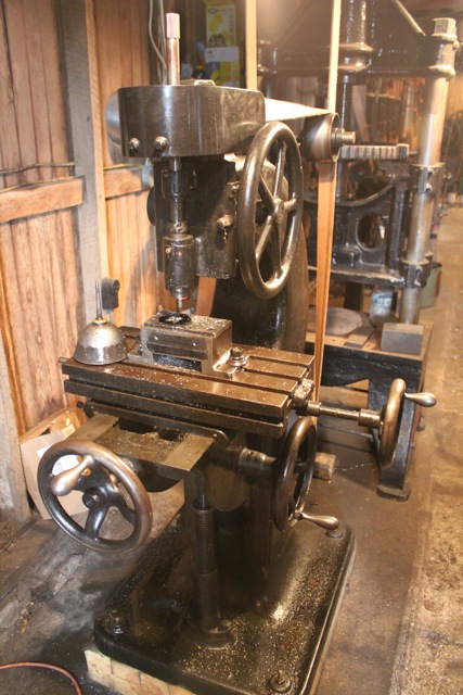
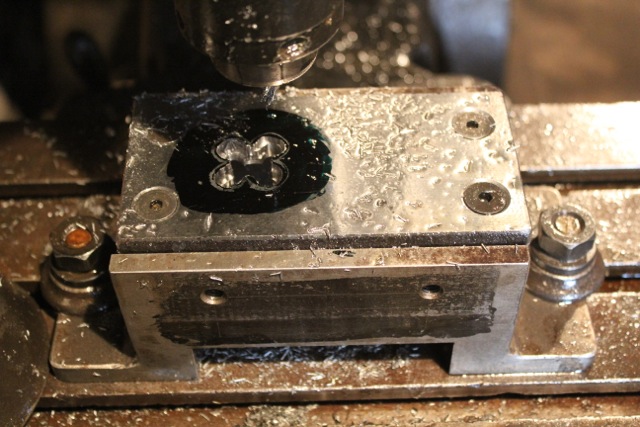
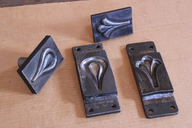
I don't have any pictures of the sheering dies for the embossed forms on hand, but here are some smaller punch and dies. Same idea, more or less. I punch out the parts hot. My toggle press is only about 20 tons or so, so doing it hot lets me do a whole lot more. Also, the sheering angles and fit are more forgiving with hot iron than with cold.
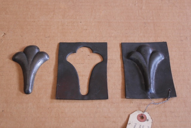
The first picture shows what will be cut out--two little flowers. I carefully cut them out by hand and then trace the outline in layout ink on the die blank. Then I remove all I can in the little Becker mill. (pics 2 & 3) Once it's as close as I dare make it, I move on to the pneumatic die grinder and a carbide burr. (No pic--sorry.) I try to get some angle in at that point, but it's only by eye. The final fit is with the die filer, which gives the relief and close fit I'm after. (pic 4) This machine has a table that tilts in all directions, an adjustable stroke and four speeds.
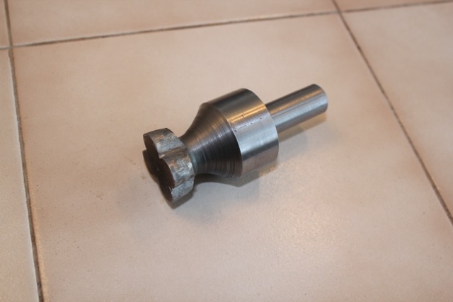
The punch is turned on the lathe first, (pic 6) and then ground and filed only by hand, (pic 7) because I can't use the die filer for this particular shape, where the base is larger than the punch face. It's tedious, but because it's all OD it's not that bad. The last pictures shows a table on which I used these little girls (and a fan, I noticed!). The flowers are on the back.
This is a wee bit off track, but since I started this thread, I guess that's okay. I don't care if you don't. Dies are so fun.


-
Thanks, Jim. I just love old technology.
Here are a couple dies I've made and fitted by testing with copper with this press. I kept a copper test piece just to show folks. There were some earlier tests which cut through the copper where there was not enough clearance between the punch and die. Once they work right
with cold copper in the try press, then I go ahead and mount them in the toggle press and give it a go with hot iron and engine power. The last shot's a table
I used some of the embossed fans on.
If anyone here's doing this sort of thing and has some suggestions, I'd be glad to hear them.


-
It was kinda rude of me to say this press is different than a percussion press and then not give pictures to explain. Here're some to show it better. The ratchet/dog, which you can see in the second picture, can be flipped either way to move the ram upwards or downwards. You can imagine how slow it is--you stand and move that handle about two feet back and forth in order to move one tooth in that big gear. I counted the teeth
once, and I think there are 48. If so, that means 24" of handle movement gives 1/48th of a revolution. It's something like that, anyway. If you take the gear and try to throw it, it only goes a quarter turn or so.
This press is absolutely quiet. If you've ever used an hydraulic H-frame press, you'll know that when you press a bearing in or out, it goes a wee bit and then POPS and then goes a wee bit more and POPS. That's the frame stretching and bending. This press doesn't do that--it just pushes steadily until it's done and never says a word.


-
There is no bounce whatsoever to this kind of press, Thomas. It squeezes. That's it. It is not a percussion press. It is built very differently than your Hopkins. It is ratcheted downwards or upwards. Single thread/lead screw presses give a slow, quiet push. It is a try press for testing dies, pressing bearings, broaching, straightening shafts and that sort of thing. It's nice for straightening shafts, because it's convenient to mount an indicator on it, and the push is so slow and controlled. I find it to be very useful, especially like I said earlier, for testing embossing dies with copper. Don't know if anyone on here's doing that kind of work or not, but I thought I'd throw it out there and see.
Do you happen to remember the two that showed up on a trailer at Quastate in, oh, I think it was 2006? They were single lead presses and built like this one but by some other company I don't recall. Nobody was interested in them, said they were slow, and they left on the trailer that brought them. I remember talking about them with Patrick, but I don't remember if you were there for the conversation or not.
Kevin, I forgot to answer your question about how tall it is. It's about eight feet. There's another Jerek press in a salvage yard a couple miles from me that has an extension, making it two feet taller. I think it's a factory extension, though I could be wrong. I tried to buy it before I found this one, but they use it there in their shop and wouldn't let it go.
Line Shaft Tour
in Building, Designing a Shop
Posted
Dave,
The main line, which is in the center of the shop and drives the machine tools, does not have real line shaft bearings which self oil; it has split babbet pillow blocks. They are lubed with grease cups. [I think I said earlier that an old bearing made for grease cups has an X grease groove instead of a straight line. That X, with the grease entering the center, draws the grease into the bearing as the shaft is turning. It could be a V, but the X allows the shaft to run in either direction.] That line shaft and all the countershafts with cups require attention every 60 hours. There is a counter in the engine room that keeps track. I walk along the catwalk and turn the cups down to the grease level, filling any that are out or are too low to last another 60 hours. If a cup has grease against it, that means the bearing isn't getting greased, and I give it attention--pull the cup and put a zerk in its place, squirt grease in and replace the cup. After the main line's done, I walk around to the machines and do the same to their grease cups, oil the machines where they need it, and so on. I have a short step ladder (an antique) for reaching the countershafts. It takes about half an hour. The other four line shafts all have self oiling bearings with oil reservoirs and rings that dip in and circulate. I service those twice a year--Christmas and on my birthday in June.
There is one bearing that is high speed and doesn't make it the 60 hours. I use #2 1/2 grease in that bearing so it stays longer, but the shaft is so low I can just reach up and turn the cup from the floor. The cup is on the end of the shaft instead of spinning with the pulley, so I can do it while the shop is running. I wish I had a picture of that, but I didn't think to take one. Maybe I will and will post it later.
Someone asked about clutches. There are two types of clutches: friction clutches with some sort of band in or around a drum, and tight and loose pulleys. The tight and loose pulley system is the simplest. It's simply an idler pulley ("loose") and a drive pulley ("tight"), and the belt is moved from one to the other with forks connected to a handle. Any two matching pulleys can be made into a set, by boring one and pressing in a bearing. The driving pulley, on the other end of the belt, has to be flat, with no crown, and wide enough to allow the belt to follow across its face when it is moved. All the old true clutches have a cast iron shoe and a cast iron drum. These are meant to be oiled. I have made some clutches, and if I can find the pictures I'll post them.