ODaily
-
Posts
18 -
Joined
-
Last visited
Recent Profile Visitors
157 profile views


-
I'm in SW Arkansas and looking for some refractory. Satanite, or Kastolite30 both come highly recommended. Anybody know where I can buy some? REALLY trying to avoid massive shipping charges. I did find FS Perry in HotSprings, but they only advertise Plibrico brand, which I'm not familiar with. May have other options, but I'm gonna have to talk to them to find out. OR maybe someone is familiar enough with Pilbrico products to steer me? There's a RAB in Texarkana, but it looks more like a service than supplies.
-
First off, I've found everybody has different names for these, but Rigid calls 'em a Spud so I will too. Secondly, that means a smooth jawed pipe wrench, but without most of the built in "rocking" in the jaw. I see quite a few people using these to Twist metal with, usually while in a vice. Most of them I see are old timey wooden handled antiques. I also always see them with a welded on second handle, usually quite crude. I need something like this, and I've gotten a newer manufactured Rigid 12" Spud wrench and a Rigid 12" pipe wrench. My plan is to cut down the pipe wrench until it can be grafted to the back side of the moving jaw of the spud wrench. It's not perfect, the handles won't actually align with the center of the work, but it's close enough for careful twisting to keep it pretty straight. It helps to think of this as tap handle with one open side. While I'm sure I can do this, I can't help but think someone, at sometime surely had something better. A factory made double spud, perhaps? Something else? Has anybody seen this addressed in another way? Just how did the wise men of yesteryear go about hot twisting?

-
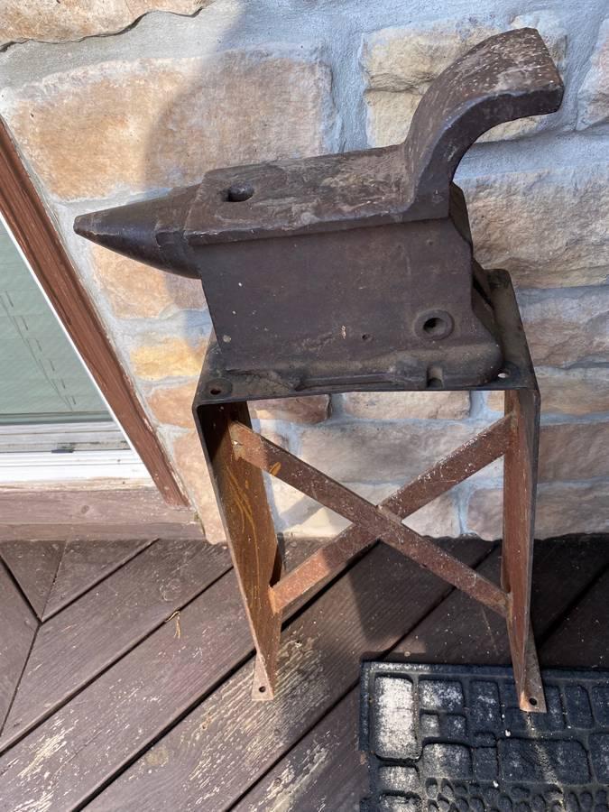
What is this weird anvil for?
ODaily replied to ODaily's topic in Anvils, Swage Blocks, and Mandrels
Isn't that something? Thanks! -
Pretty much just curious what the heck this would be used for. Unique design to me. Best guess, = Saddle / leather work? Also, it's A: not mine, and B: on C/L in Camdenton MO, USA. I just found it whilst browsing.

-
Modifying a 5.4L Ford Throttle Body for a forge valve.
ODaily replied to ODaily's topic in Bellows, Blowers
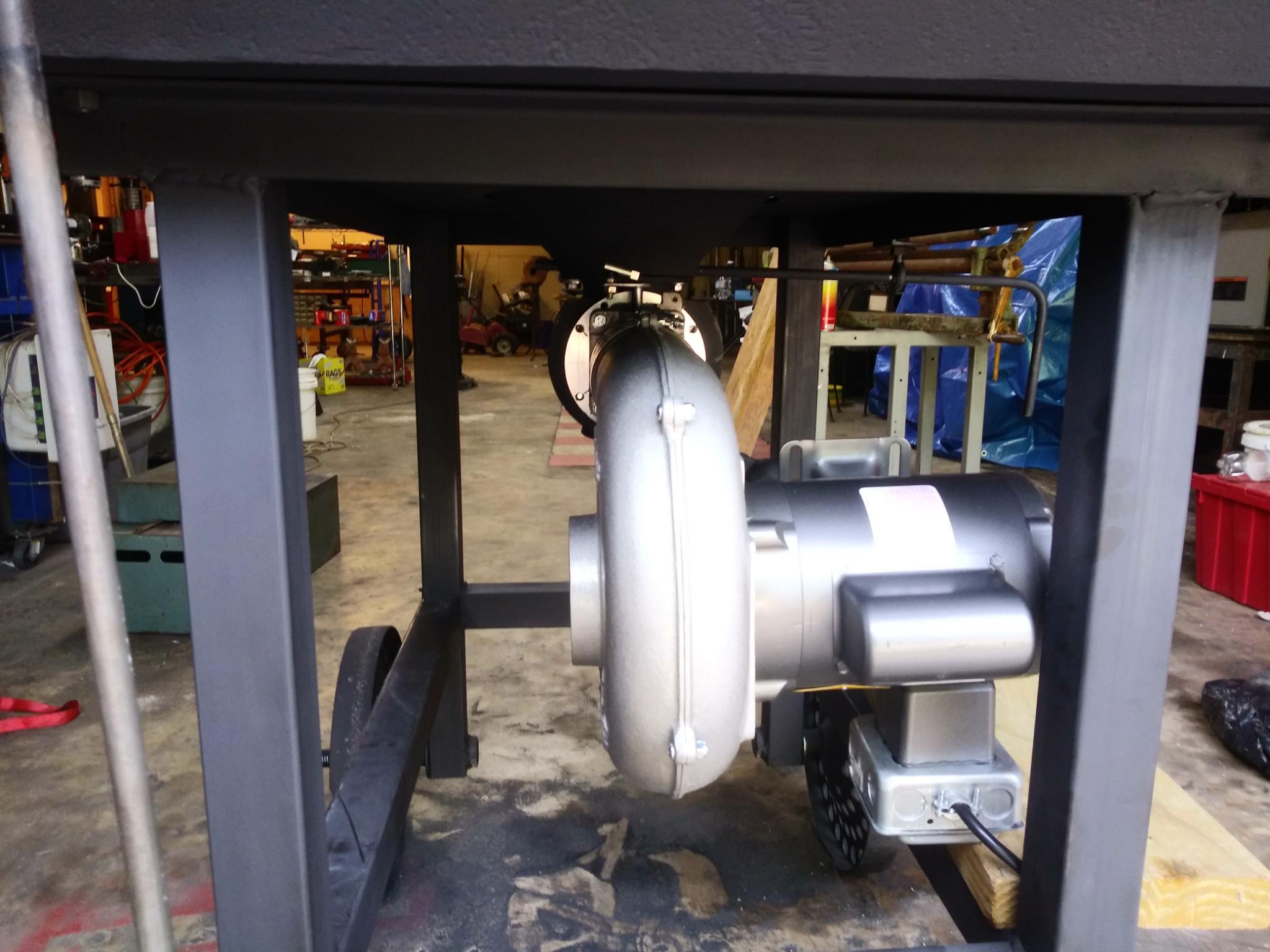
I needed to choke off the air intake. I used a shell of a mower muffler. The perforated holes let just the right amount of air in to put the valve in a useable range. By useable range, I mean from this is pretty hot to surface of the sun temps. Just flat wow. Everything I've learned to this point was on bitumenous with a handcrank. Anthracite with electric is a much different beast. I really wish I would've built a diverter style valve. The blower is capable of insane for a newby heat, but can be ticklish to dial in as a result. Maybe I'll redo it at some point. Anywho, pictures..thumb.jpg.f33a889348f70ad300df2ef1b3c0e734.jpg)
.thumb.jpg.43ec6f2161bf2843e02dc7b7a3525528.jpg)
-
Modifying a 5.4L Ford Throttle Body for a forge valve.
ODaily replied to ODaily's topic in Bellows, Blowers
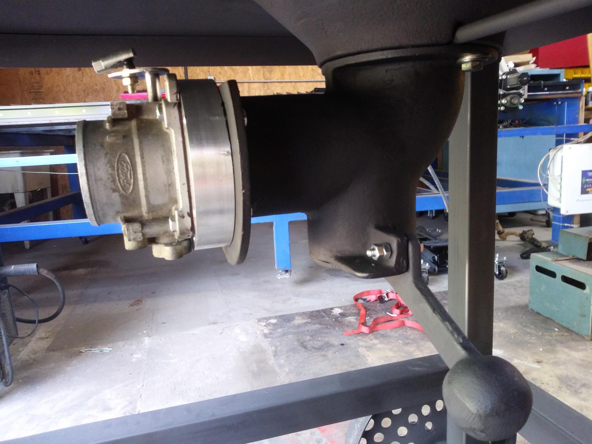
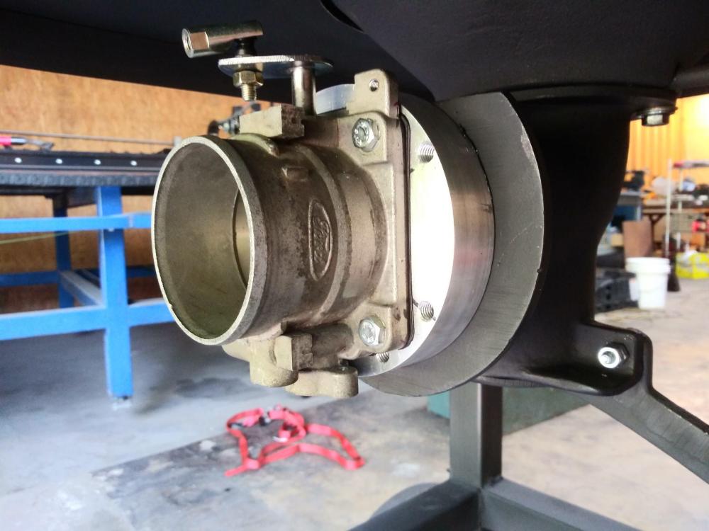
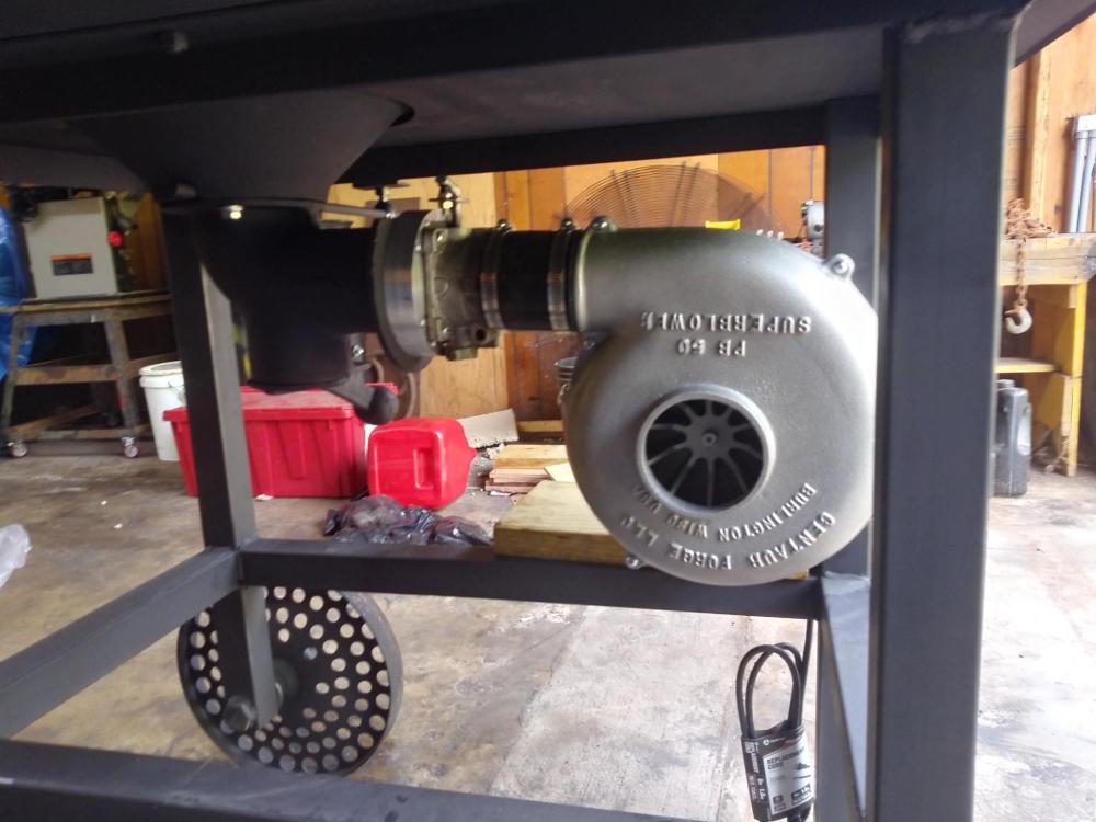
Thanks! But.. Forge isn't working yet. The blower is attached by 3" silicone hose, and is seting on a scrap of wood. Next step, mount the motor on a plate, move the control / switch to a more convenient location, and fabricate a control rod / lever for the valve. Then I can fire her up. Also, I forgot to mention, I cut the adapter out of 5" round, but that's the absolute minimum that can be used with the bolt holes on the CF unit. It uses a 4" x 2-3/8" bolt pattern, assumably the same as the dayton blowers. If I had a bridgeport, I could be more accurate. I guess I need a bridgeport. -
Modifying a 5.4L Ford Throttle Body for a forge valve.
ODaily replied to ODaily's topic in Bellows, Blowers
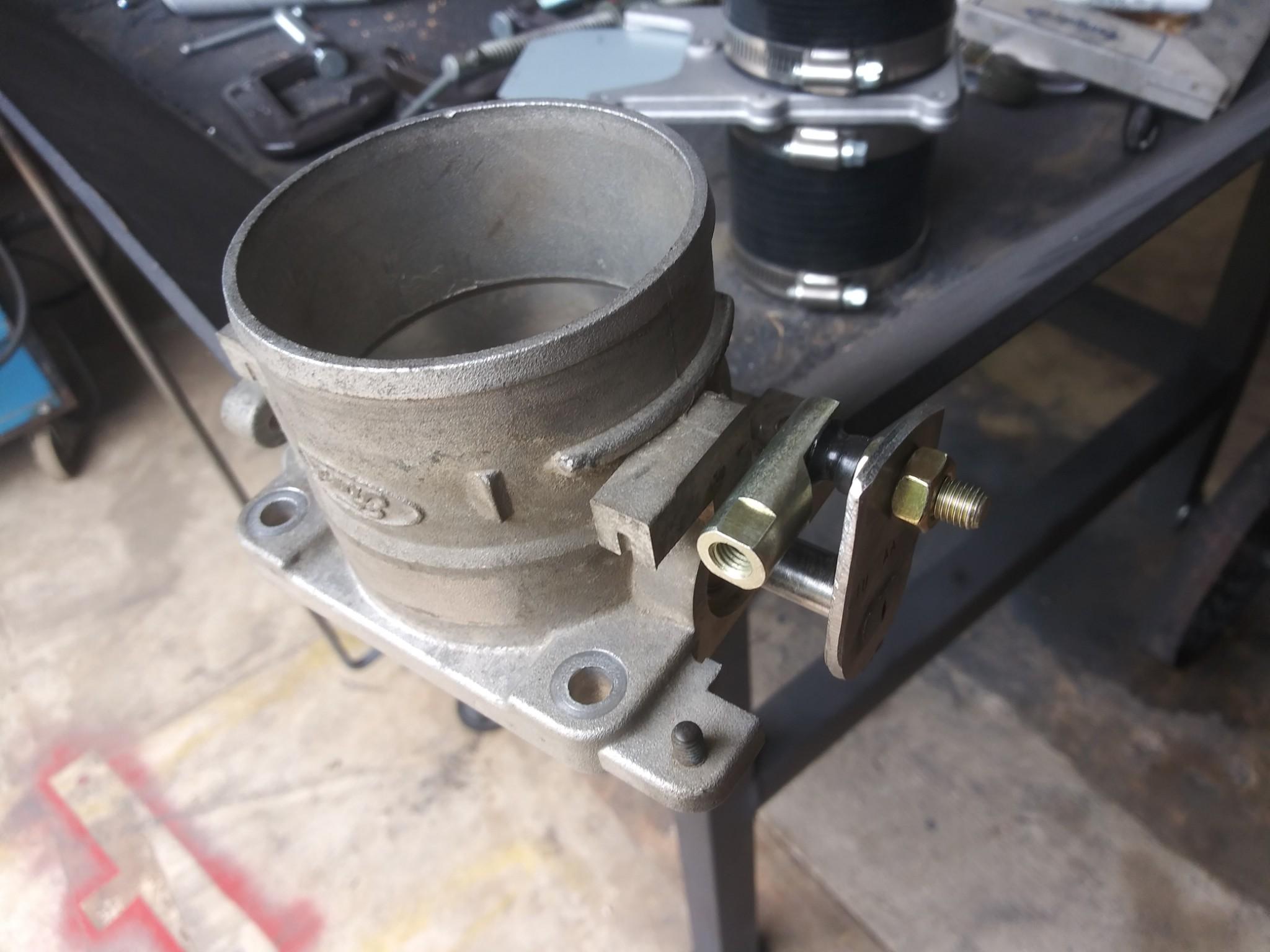
I made an adapter from a piece of 5" diameter, 1" thick aluminum. I could just as easily have mounted it directly to the tuyere if I drilled holes in it's mounting flange. I didn't want to. I could also have made two flat steel plates and welded them to a piece of 3" pipe to make an adapter. I had aluminum, I used it. I matched the through hole to the TB at 2.85" diameter and beveled the backside out to match the tuyere at 3.1". (Does NOT need to be that precise.) Then I messed up drilling hole patterns, and had to turn everything 90 degrees and redrill to the correct dimensions. Measure once, cut twice, ya know. Mounted it up and started on the fan. I still need to build a rod to control the valve (push/pull style). I'll also need some friction on the rod so it doesn't just randomly move. But, that's tommorrow's problem.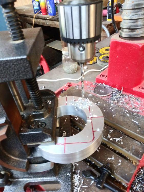


-
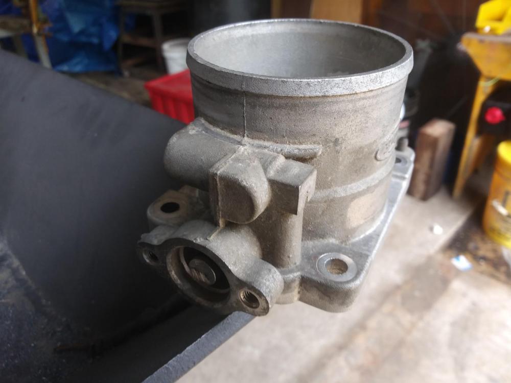
This came up in a different thread and I thought I'd start a new one to document what I've done in case anyone else wants to try it. Basically I'm modifying a Throttle Body of of a 5.4L Ford engine found in various trucks in the early 2000's. This was selected for it's 3" hose attachment, and being the simplest available with the fewest sensors, valves, and passageways to deal with. First you'll need to snag one off of the previously mentioned engines. There are cable operated and fly by wire types. You'll want the earlier cable type. Also be careful not to get one off of a v6 as they look the same, but are smaller. Step one, unscrew and discard the throttle position sensor. Next remove the two screws in the throttle shaft that hold the blade on. Rotate the shaft so that you can pull the blade out of the shaft. It only comes out one way because of two stamped bosses in the blade itself. Make sure you not which way the blade is oriented with regards to the housing, it has beveled edges that are hard to see, but you want to put it back the same. You should now be able to tap the shaft out of it's bore. You'll want to unhook the spring as you get it moving, it just clips onto the housing. Discard the spring. Remove the O-rings from the throttle shaft. Now clean everything. Good quality carb cleaner is a must to remove the carbon sludge, particulary inside the throttle bore. Now that it's all clean, we can modify. I chose to trim the end of the shaft back where the Throttle position sensor was. I just ground back the "blade" looking part that sticks out. This is optional. There's a hunk of molded plastic on the other end of the shaft. You can remove it from the metal part with a wire wheel on a grinder. This should not hurt the steel bracket. The bracket on the throttle shaft sticks out far enough that it will hit if you mount the valve on a flat surface. You can either: A, make a small riser block to go under the valve, or B, turn the valve shaft 180 degrees and cut most of it away. I chose B, see pics below. I chose to drill out the one remaining hole for a 1/4" connector to bolt to. I'm going to use a rod linkage, but you may want to use a mower throttle cable / choke cable / PTO cable. Re-assembly time. Put new O-rings on the shaft and tap it back in. Double check that you've got the shaft oriented where you want it, and slip the blade in place. A. Do not screw it down yet. B. double check that it's oriented correctly. It should be exactly the same as when you removed it, whether or not you rotated the shaft 180 degrees. Now close the valve. That will line the blade up exactly on center. Install screws, and it's all locked in place. I'll be making an adapter plate to get it bolted up to my forge, but you should know the bolt pattern on the TB casting is 3" x 2.6" and the holes are sized for 1/4" bolts. Once I've got that done, I'll get some more pictures up.

-
Are you familiar with PWM (Pulse Width Modulation)? It's basically rapid switching on/off with the length of the off time varied to adjust the duty cycle. 1/2 power is off 1/2 the time. 1/4 the power is off 3/4 of the time and so on. I searched for "120v ac pwm" and the second unit listed was 6.59 Just be careful, lots of mis listings. Looks like a few are trying to sneak rheostats in a fancy case off, so read before you pay your money. There's a 4 pack for 10.99, for that kind of money you could probably take the risk?
-
I can do simple. It's just gotta be elegantly simple.
-
This is a little long and messy, so bear with me. Also there ARE broad holes in what I'm going to say, but it's close enough to understand without a need for perfection, so if you're an electrical engineer, try not to flinch and please forgive me. The speed of an AC motor is controlled by the number of poles and the AC hertz. In the U.S. it's 60hz and motors have 2 or 4 poles. Which is why you always see 3600 rpm or 1750 rpm motors. The correct way to change the speed of an AC motor is to change the supplied hertz with a variable frequency drive. Those however are Very expensive and pretty complicated. They do however give PRECISE control of the motors rpm. That said, not really suitable for a blacksmith's shop. The above all assumes that the motor in question is rated for a workload greater than the work it's trying to do. So basically not overloaded. The contol on this motor is a rheostat (light dimmer -easy cheap common solution) that is just a variable resistance. It's basically used to reduce the available power level to derate the motor. As the motor's rating decreases it should be dragged down by the load to a slower rpm. And for the most part, it is. But It's a kinda mushy control. As the rpm decreases, so does the load, which reduces the effectiveness of the derating via the rheostat / dimmer. A motor with no load at all, would still be moving at nearly the full rpm, and fans don't really create a whole lot of load. The solution is to increase the load at the same time you derate the motor. Hence the valve and the variable speed. They work together to deliver better control than either could by itself. If you have just the rheostat / dimmer, then the load is the clinker breaker, coal pile, and whatever clinker has formed. The last two are constantly changing as it burns, and the setting on the motor is to hard to find much of a sweet spot with. You'd mostly end up with too much or too little. If you have just the valve, then as the load increases, the pressure goes up, allowing more air through the smaller opening, defeating the effectiveness of the control to a significant degree. This is why people with constant speed motors like the bouncy castle use a diverter to blow off part of the air, basically derating the air supply by "leaking" it off. That is perfect. And 250 dollars. Nice dumpster diving though. Yeah, it sounds like you get me. Full throttle or nothing. I tend to aim high. I miss alot, but when I connect, I like to knock 'em out of the park. A day at the junkyard yielded a nice valve off of a 2000's Ford 5.4L The 4.6 has the same valve. I need to ditch the TPS, and create some linkage, but it looks like a very simple and workable piece otherwise. I may need to make a riser block for it, so it doesn't hit the control arm while rotating. Also if anybody else tries this, the later models had a drive by wire electrical motor instead of a throttle shaft. The V6s had a very similar valve, but about 1/4" smaller. Avoid both.
-
Got a pic? I did recently find some sealed metal gates that are the same design as an RV dump gate. 360 dollars. It's two hours to the nearest steel supplier. I usually just deal with the local hardware store, or scrounge. Speaking of which, I'm off to make the trip to Little Rock and see what the junkyard holds. You never know.
-
Most of me knows the standard blast gate will work fine, leaks and all. My inner perfectionist however is howling at the thought of putting it in the middle of everything else that's so much better built. Besides, exploring options sometimes opens up new better ideas. Never thought of it that way. And I like it. It might just be very practical for an electric, and so so satisfying to watch work.
-
I've been building a coal forge with a CF pot and electric blower. Long story short, I overdo things. In this case a beautifully heavy forge with all the trimmmings. But. I'm ready to mount the blower, which means mounting the blast gate first. I just couldn't bring myself to put it on there. (I tried, I really really tried.) It's just such cheaply made junk. I realize that's what everybody uses, but it leaks everywhere. And it's just so... cheap. This led me to looking for alternatives, and I thought I'd share / brainstorm. If nothing else maybe this'll help someone else out someday. (Good luck, Buddy!) 1. I could rebuild the blast gate. Smooth it up, and put in a thicker slide so it doesn't have such a huge gap. This is probably the most practical of all the ideas, but it will still leak, just less than before. Still seems like a bad compromise. 2. I thought about a 3 inch RV wastewater valve. It's a slide type valve too, but much better sealed. It is however all plastic. I couldn't find any with a metal construction. A shame really, cause If I wasn't worried about accidentally scorching or igniting it, this would be an excellent alternative. 3. There are a bunch of variations of homemade valves that vent the excess air. (Check YouTube.) These look excellent, but my tendency to overdo is likely to go nuts here. Besides, I have a variable speed fan, and should only need to block the air, not vent any. Plus I don't really want to build entirely from scratch. 4. I Really kind of like the idea of using a Chevy Vortec throttle body. Could be easily adapted to a machined plate, and is almost the perfect size. Cons are the outrageous price junkyards charge, the extraneous bits that might come with and need to be deleted (IAC, TPS, etc.) Getting an earlier cable controlled model and attaching some kind of lever to it is an issue as well. Also, I'm not sure how blacksmithy it feels. I mean sure I've got an electric blower, but TBI? 5. I really like the idea of an iris type valve. Pro models are VERY expensive. But... there's a metal iris being marketed as a dawing tool. Google "Iris drawing tool". The original is expensive, but there's a bunch of knockoffs available. It has a max 3" bore, and closes to nothing with a quarter turn. Cons are I'll have to heavly modify or totally rebuild to turn it into a valve. But it's just so cool. I ordered one, cause it'll be cool no matter what I use it for. (FYI, it very much makes me think of Stargate). 6. Theres another iris option. Iris valvs are use for flow balancing in HVAC systems. The smallest valve is a 4". Google "Iris air damper" to see what I'm talking about. One major flaw, they don't completely close, looks like about a 1.5" hole remains open. I could put something permanently mounted in there to occupy and block that middle space. Being a 4" valve on a 3 inch pipe might actuall work out about right for surface area. I wouldn't even want to fully block as I'll always need a little air to keep the fire alive. And if I want no air, I can just switch the fan off. Plus it's almost completely premade, sealed, and basically designed to regulate airflow in a pipe. 7. There's also a radial air damper designed for inline HVAC duct work. It consists of sever small hourglass shaped panels all on a central bolt / pin / pivot. When rotated one way, they spread out, rotated the other way they stack up. Going this way would require homebuilt however. I could not find any smaller than 6 inches in diameter. Anywho, that' what I've been mulling / obsessing over lately.
-
I've seen those recommended, and also dismissed. My understanding is that a squirrel cage style like that, while moving plenty of air, lacks the ability to build significant pressure. Hence the use of the straight blade radial style fans. Most of this I've picked up from reading various threads here on the forum, but it makes sense to me. The firepot I'm using is a coke firepot. The recommended blower for it is 500cfm in free air, with a straight blade radial design, so assumably at least a little bit of w.c. pressure. Obviously you wouldn't run it wide open all the time, but I'm basically trying to duplicate that fan's parameters without paying the 728 dollars just to tear it apart for a dual drive conversion. Besides, I can always run it slower. I actually thought about this, but the other way around. That way I could have the hand crank out in the open, and the electric mounted under the table and out of the way, and out of sight. The electric seems just a touch out of place. I'm glad you brought it up, I may revisit it. It'd certainly be simpler. Also, sorry about the commercial link in my previous post. If anybody's curious, it is, or was, a Dayton Model 6YG63.
.jpg.5fb7397a6593fac0a971313187a040db.jpg)
.jpg.e20b3676ee6425c1e852965c4c1e80c0.jpg)