
James Bond
Members
-
Joined
-
Last visited
Everything posted by James Bond
-
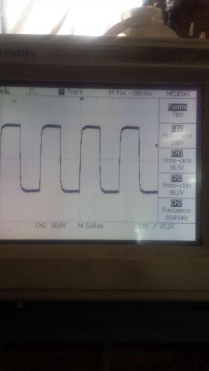
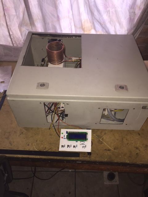
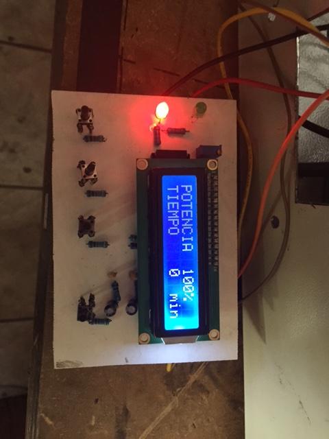
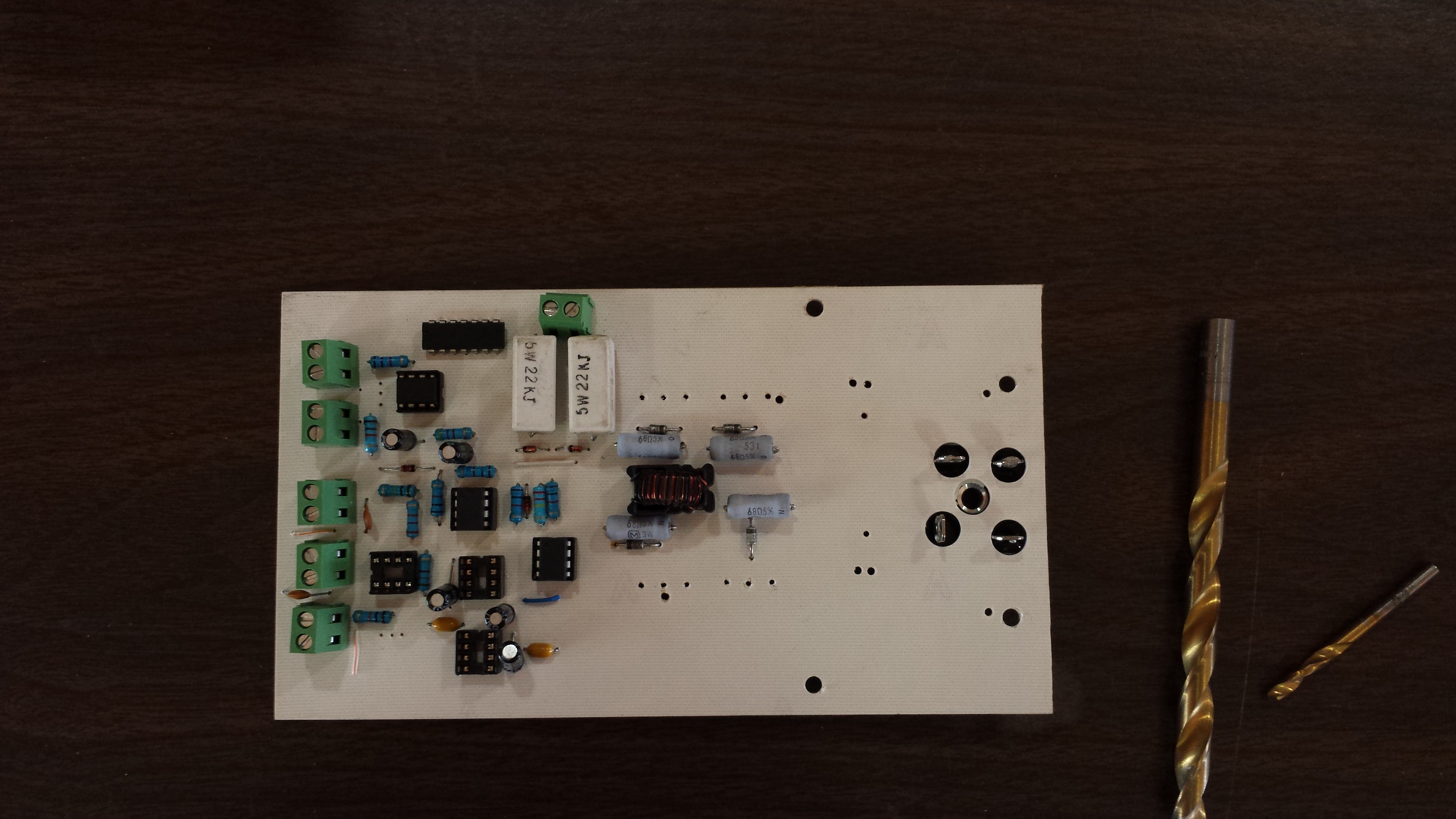
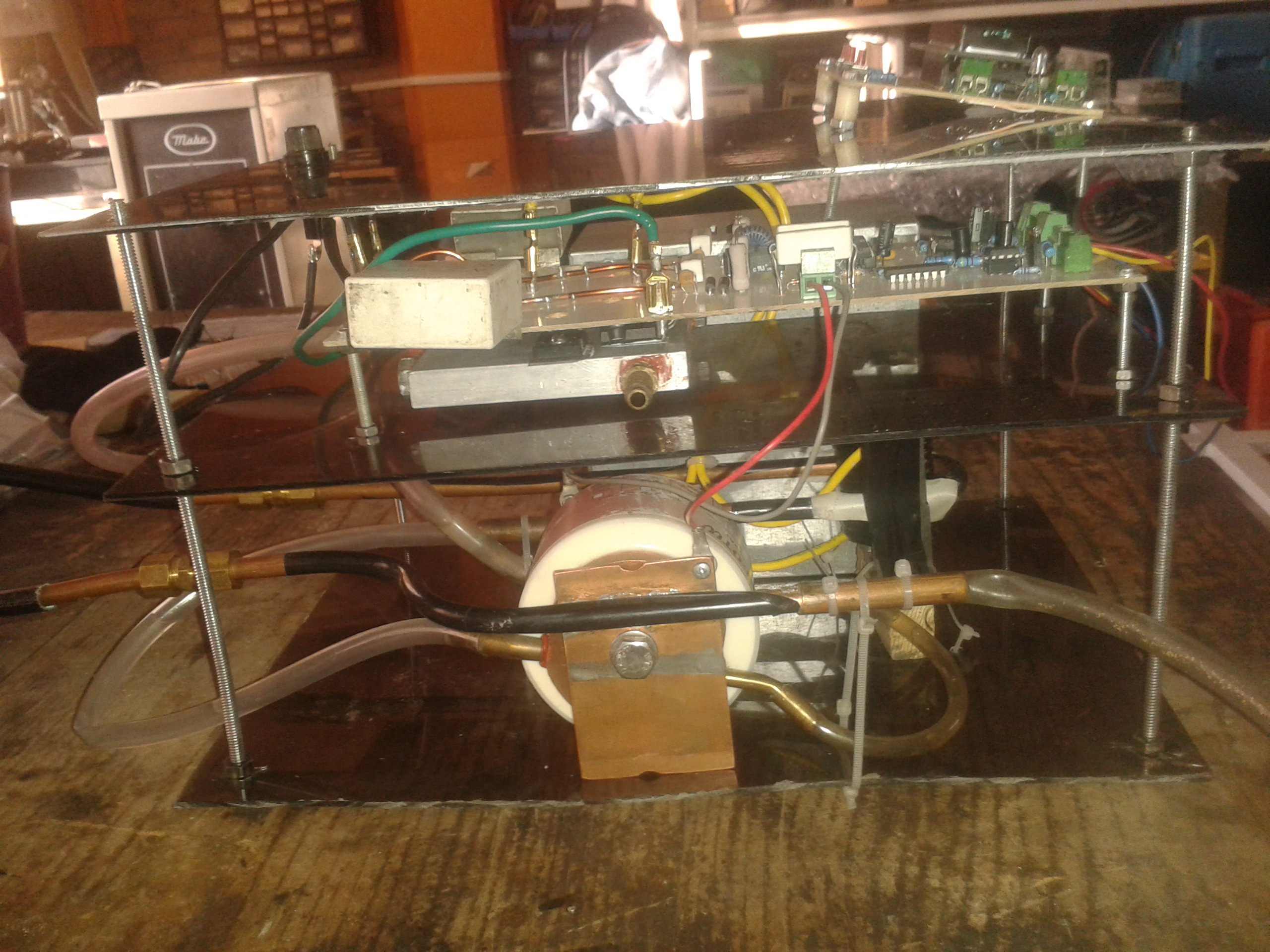
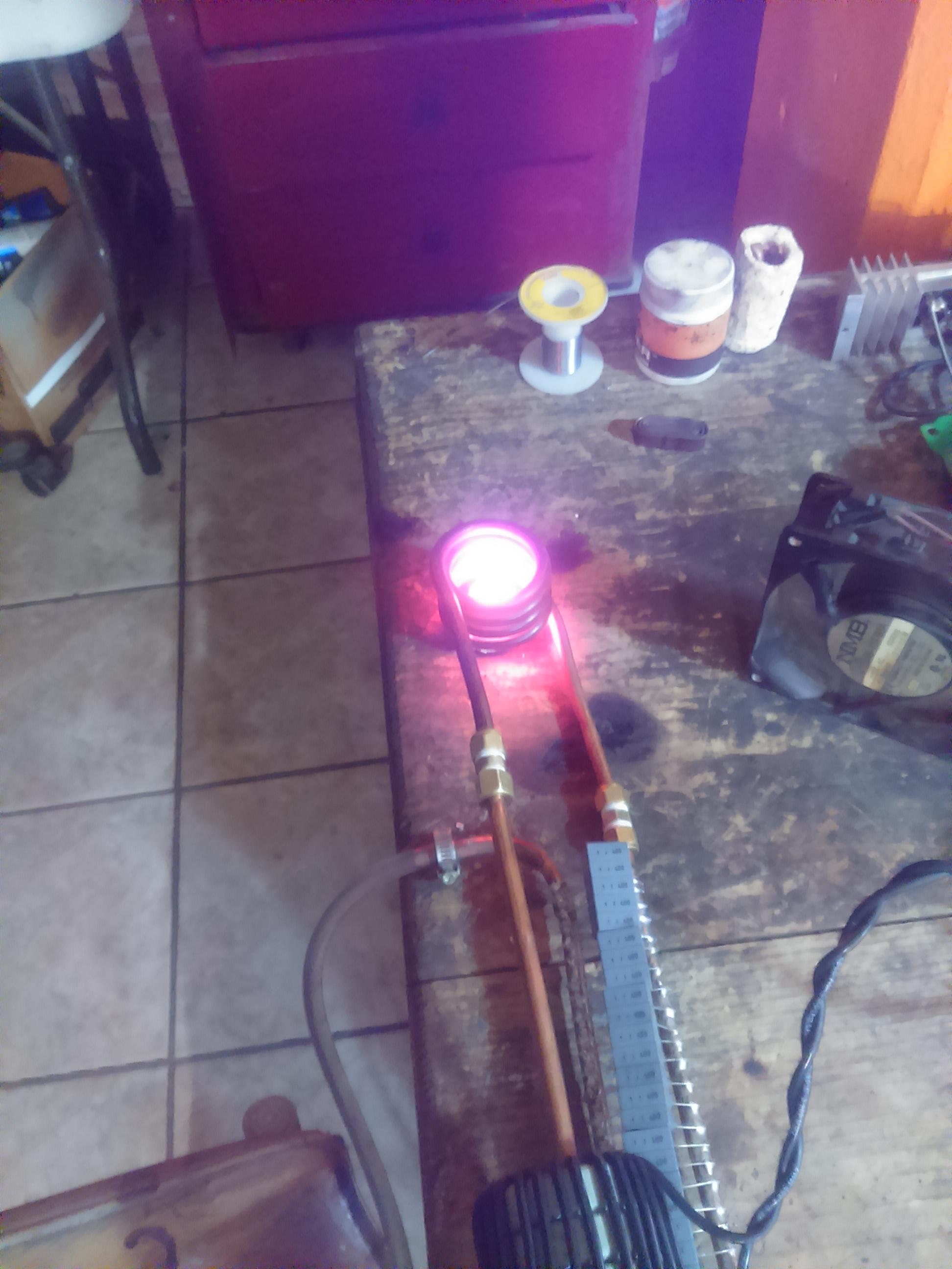
well i was workig in the control of the induction heater and i put a lcd 16x2 so you can set power and time before start work, i change the tank circuit because my friend Joshua C. told me than the old one waste a lot of energy. and he was right. cooler sistem its a very bad idea but works fine four 12vdc high flow fans and two computer radiators. jeje thanks Joshua C. the system works grate at 4 kw and and I think we can get up to 7kw.ok i was very bussy this weeks because my job its very demanding, but i finally finish the new control, it works very fine in the induction heater because my goal is to maintain the current stable no matters the size of the piece or the heat or the material and i can say this thing works fine. also i introduce a safty control if something gone wrong.hi my friend joshua on the internet I have seen some very interesting concentrators. for example the induction cookers They have some ferrites under their coil that I suppose serve to concentrate the magnetic field upwards of the coil and in this way do not waste energy. I am right? I send you an email my email is email removed I attach an image and a link to a video on youtube 3:16 https://www.youtube.com/watch?time_continue=5&v=jOg8Q-jt1BY https://www.youtube.com/watch?time_continue=2&v=Dsc8vzSQDP8
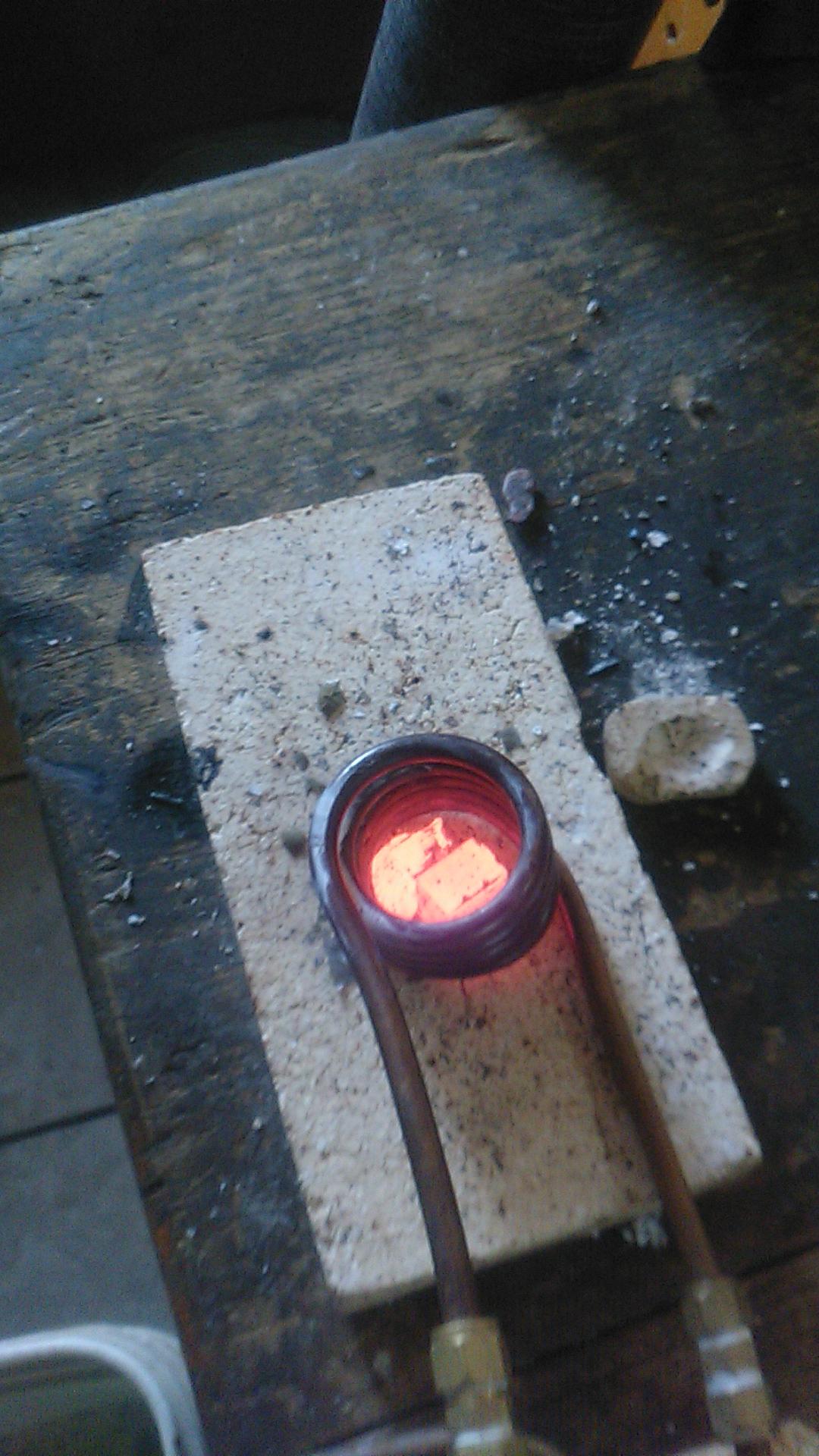
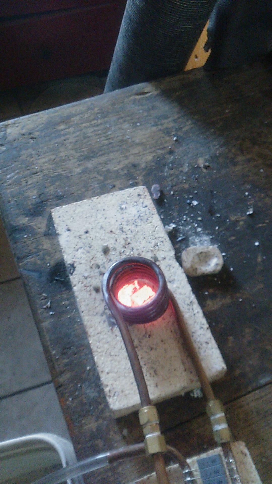
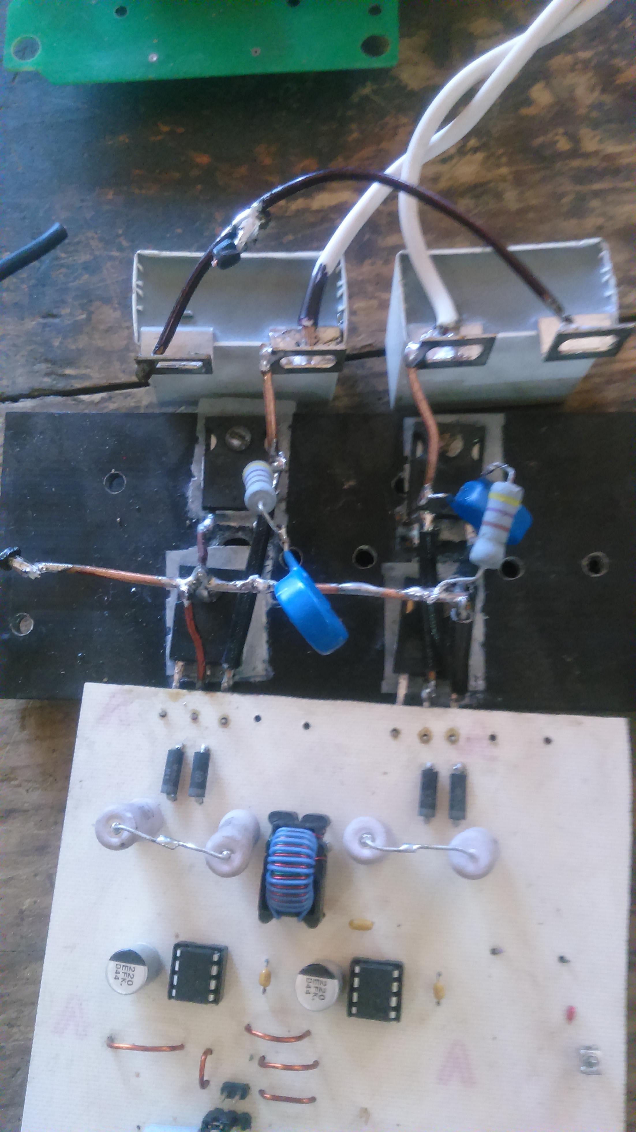
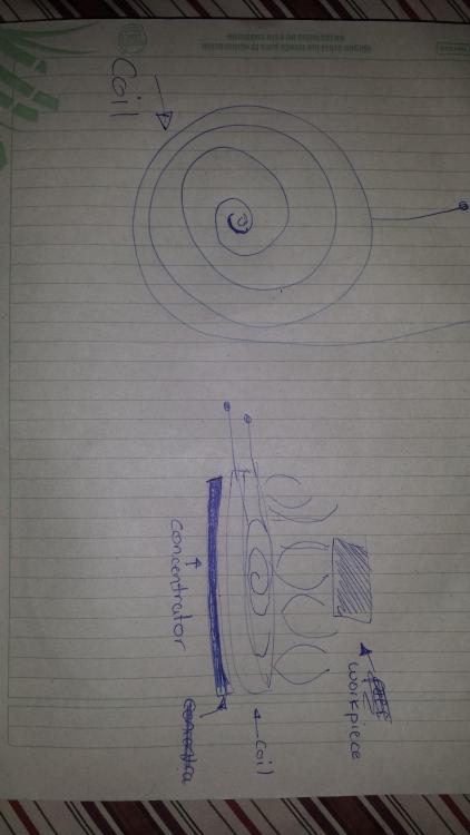 I am not the great student of electronics that you think and I do not know many things about many subjects. My main problem is that I do not know many people who know about the subject of induction furnaces. I would like to have some mail or something to be in contact with you. Today I have several doubts. I have seen a material called flux that serves to concentrate the field of induction coils. it is very expensive. Is it possible that some more common material will be useful for this experiment to concentrate? since for example I would like to make a coil like the induction heaters but concentrating the field above the coil. I am trying to make a current sensor by measuring the input current from the input line and not from the inverter. is this ok?Reactor forge its amazing.! good jobwhen i heat some material the current rises and it can be dangerous i need a current control. first i need mesure current. if a have advances i will post .ok let's se point 1: come on!! a Variac !?! come on........... 220VAC line point 2: That is a good idea point 3: I don't have a power factor meter but each blue cap are 1uf/250vca so i have 2uf total. point 4: yea! GDT!!!!. hybrid drive are very expensive and you need 4 and 4 dc-dc powers supply if you know for some cheap let me know. point 5: we need to discusse this point. I'm working with pic microchip and i have a range from 10khz to 500khz . i dont know anything of Atmel microchip but i understand a little bit your power stage controll and im in love with this ...it's a shame that in the web nobody explain the power stage controll. in mexico nobody knows about atmel. you can controll the power of your unit always at resonance... boss! point 6: well i can do this ..but later point 7:ok i have two more that I can stack. i think i'm saturating this one . they are 3c90 material chinese units haha point 8: thanks i have to do that my new friend josh thanks for your time and help mePlease repost in a normal text formatsince now I'm using a pair module igbt. and im workin with 240vca. and i have a new board too. Im working at 245vca and the induction heater consume 25 to 23 amps. 6KW of power for small pieces its ok !! i can melt 5 or 6 oz of cuper in 5 miutes i think its a big step. this induction heater works fine very well but if i want go to higer levels 15 kw for example i need to do another topology but not now maybe 2018.
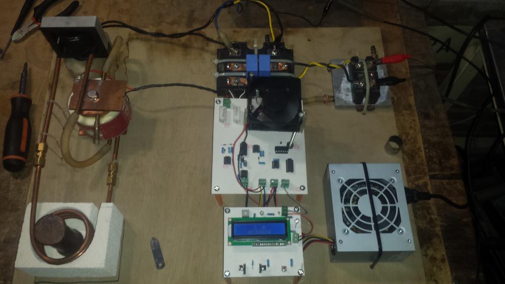 oh yes, friday i will post.i finish the full bridge inverter i have some problems but i think we are ready i think this induction heater cosumes 20amp at 120v 1phase i will show you a video.
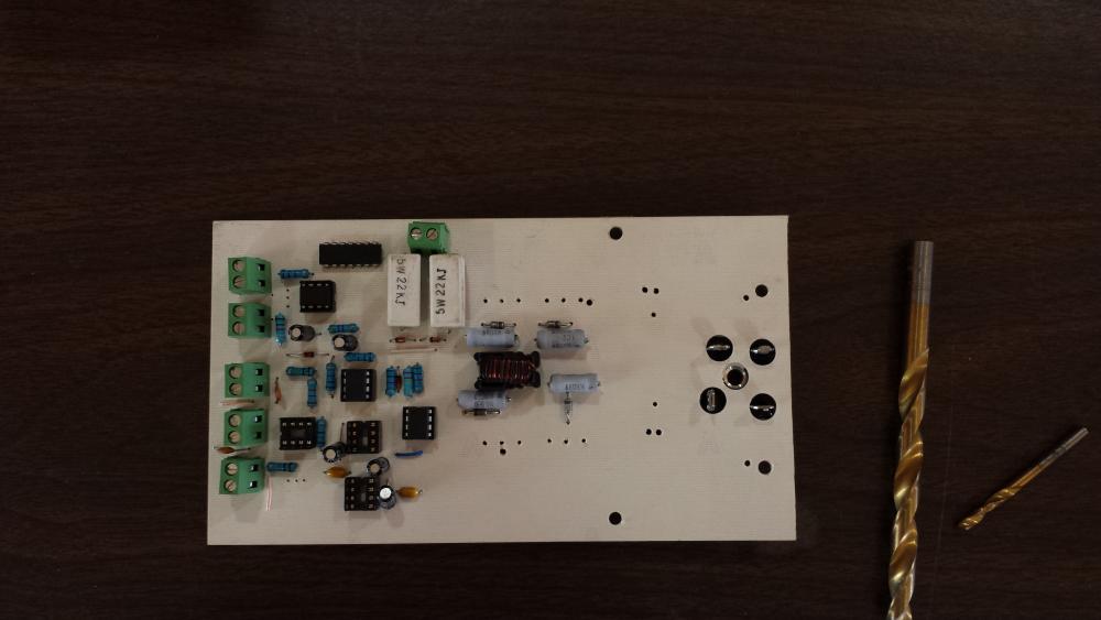
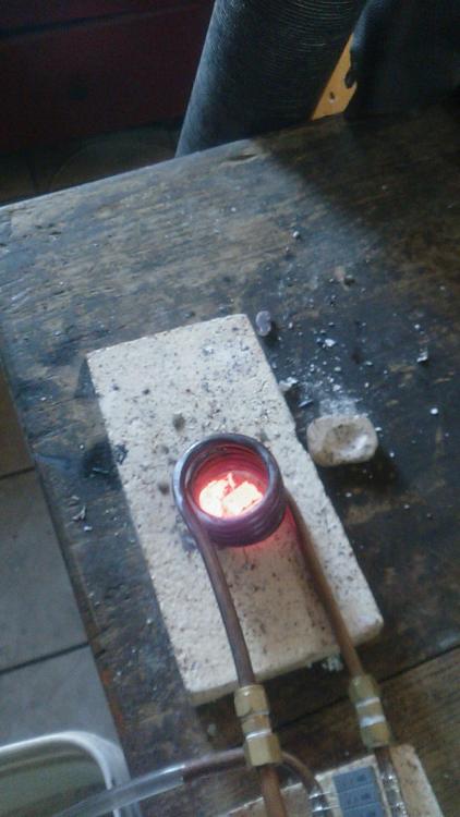
 i have a idea but i need time u will seeEverything seems to work fine, I try to work with a complete bridge inverter But I have several problems, The most important of them is the following, when the piece begins to heat its resistance begins to decrease and as it is in resonance the current rises to high levels so that I need a good control of current, Going out of resonance frequency does not seem a good method to me since this stresses a lot to the igbts and the power factor is bad. I would not like to use a controlled rectifier as it would increase my costs by having to buy half power scr as well as generate pulses and blabla bla The real problem lies in the topology .... since it is the most common topology and most used by home induction furnaces. Is a good topology but it has weak points a disadvantage of this kind of topology is that the heater will pull huge current when it run at nun load situation.and you have to put a current limiter to protecting your circuit in fact your heater power has hardly increasing with decreasing of load resistance. LCLR matching network has a gear ratio that varies with load resistance.actualy when you put a heavy load into the workcoil the gear ratio will be highest and your current will be low.and reverse in null load. and also your resonant frequency will be change . another disadvantage of this stuff is that for increasing the output power you have to decrease your matching inductor value and this is not good beacause the matching inductor supresses the current spiks of the inverter .and when you decrease. it cause this current spiks to damage your transistorsI already have the new design ready with power control and a much better tank circuit the system has changed a lot and with notable improvements. Out of the tank capacitor everything else is very economical This version work with 15 amp 115 ac And behaves very stable I have to upload video next timeI have bought a special capacitor and I have also worked on a better control circuit cheaper and better, I'm still with the half bridge inverter, I have a pretty good power control and my heatsink works very well.I turned on and after several attempts and adjustments and burned igbts I could put to work the induction heater could melt small pieces of bronze copper aluminum and iron in 1 or 3 min I guess that's a long time, 80gr I want to make a new design and design a better control, a better capacitor tank since this does not convince me for higher powers I plan to keep the same cooling system and also keep the same half-bridge inverter, I want to change the high-frequency transformer We'll see what happens


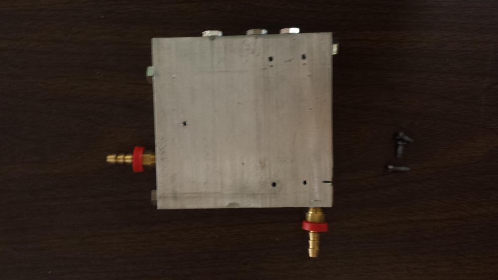
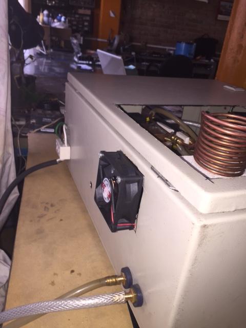
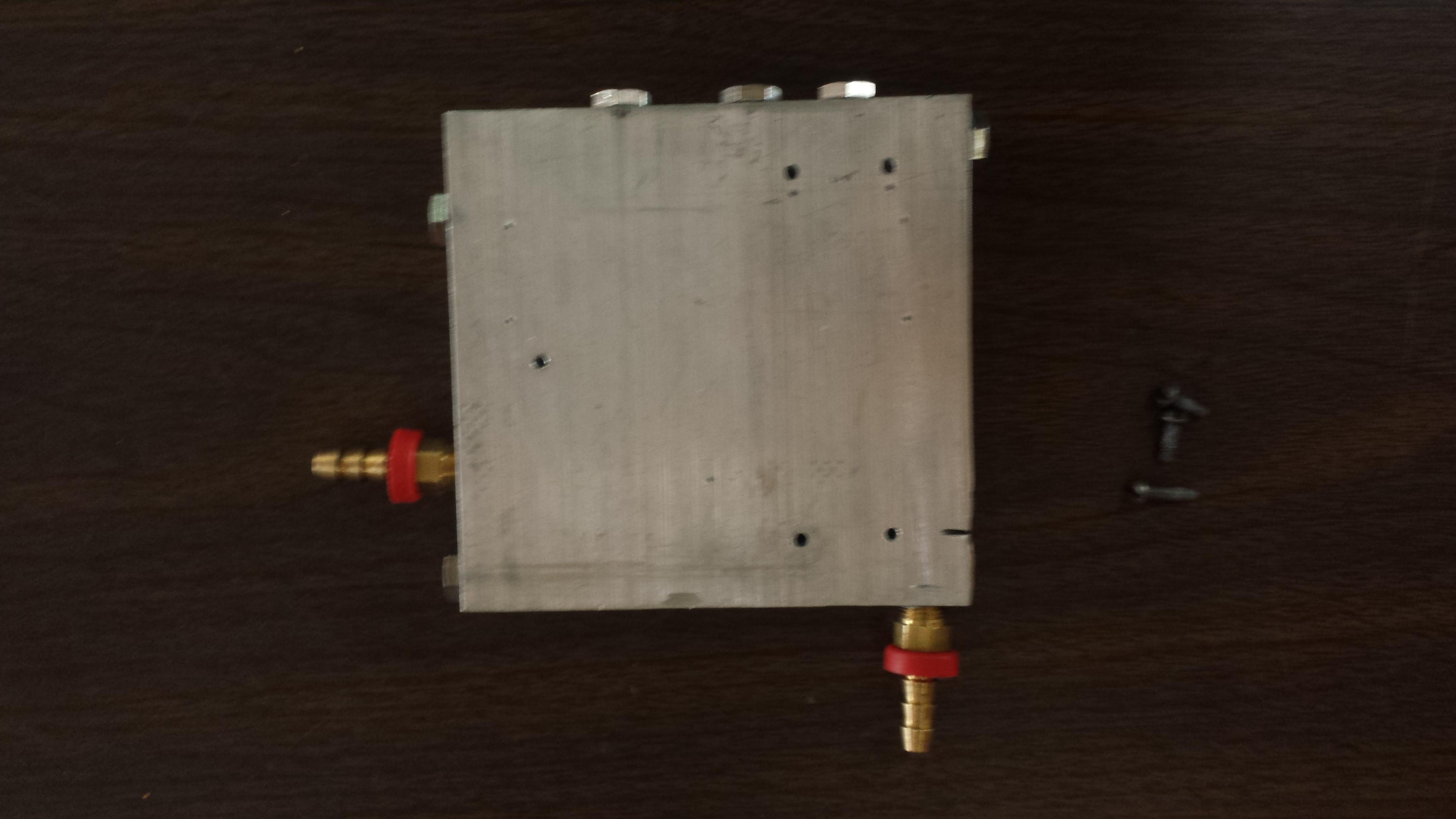
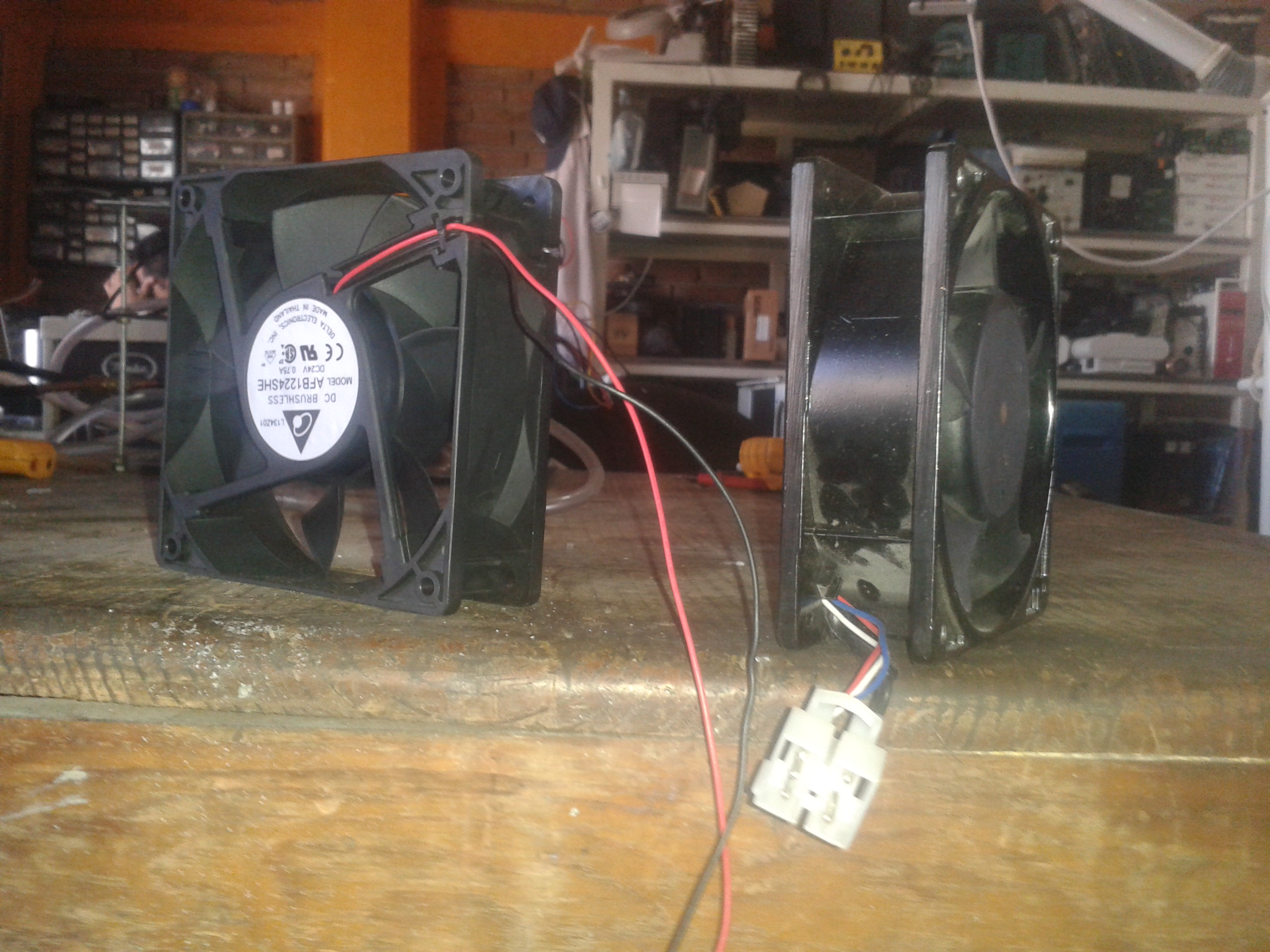
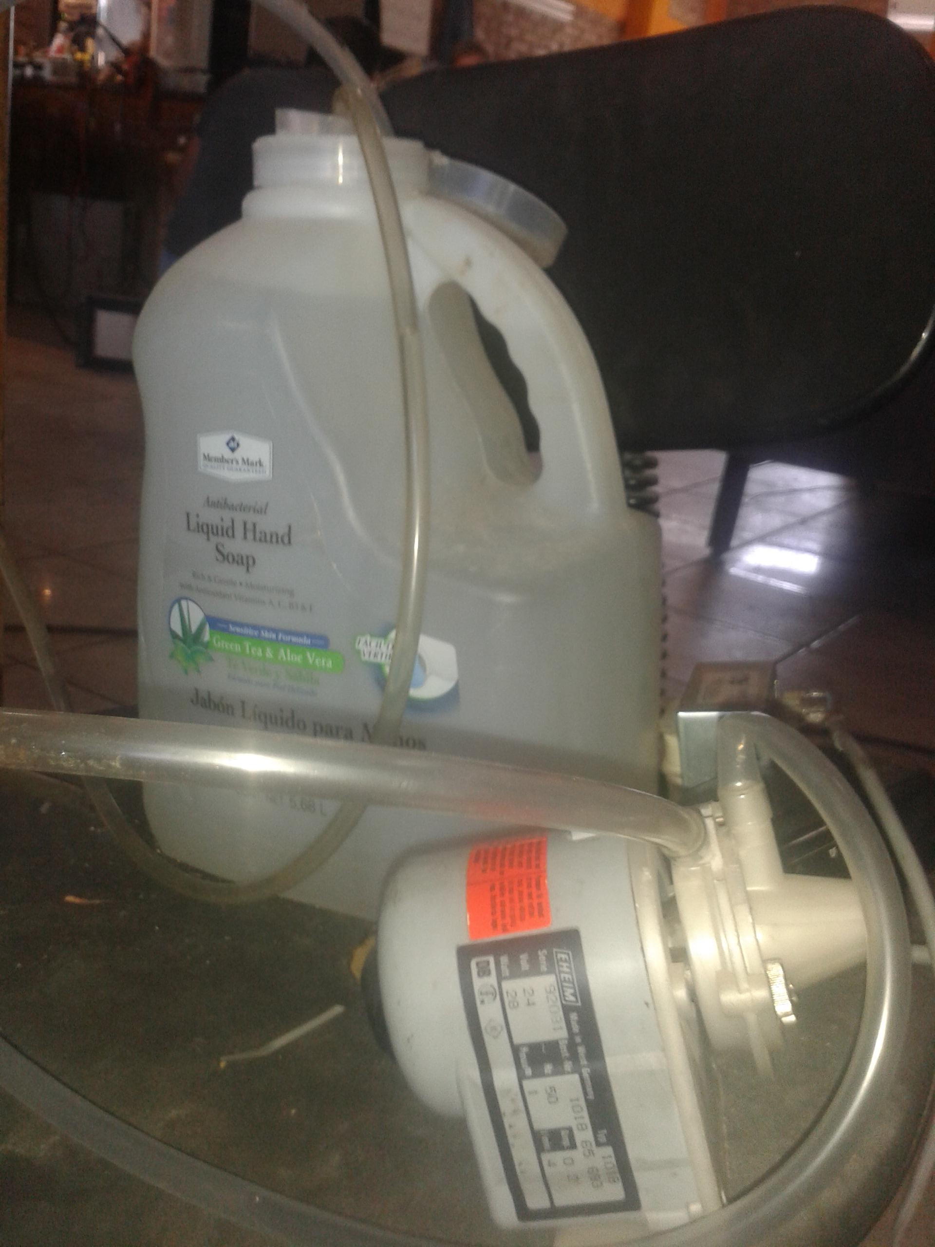
 you are right hahagood morning friends. cooling system I have seen on the web, different cooling systems that are very expensive but effective, I think I will design mine based on heatsink and fans, I need fans with high airflow and a radiator about 24 or 36 cm A small water pump We'll see if it works the way we want and how effective it is, We need this water passing through our tank circuit and since we will work with water system we are also circulating through the heatsink of the inverter so that they are always in good condition. In the event that water does not pass through the tank circuit it would heat up to self-destruct
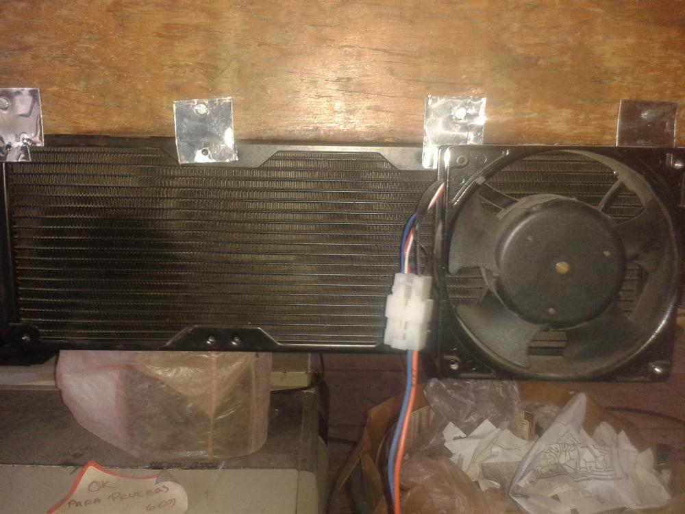

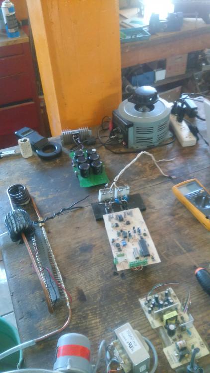
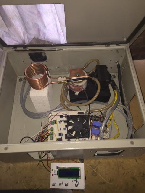
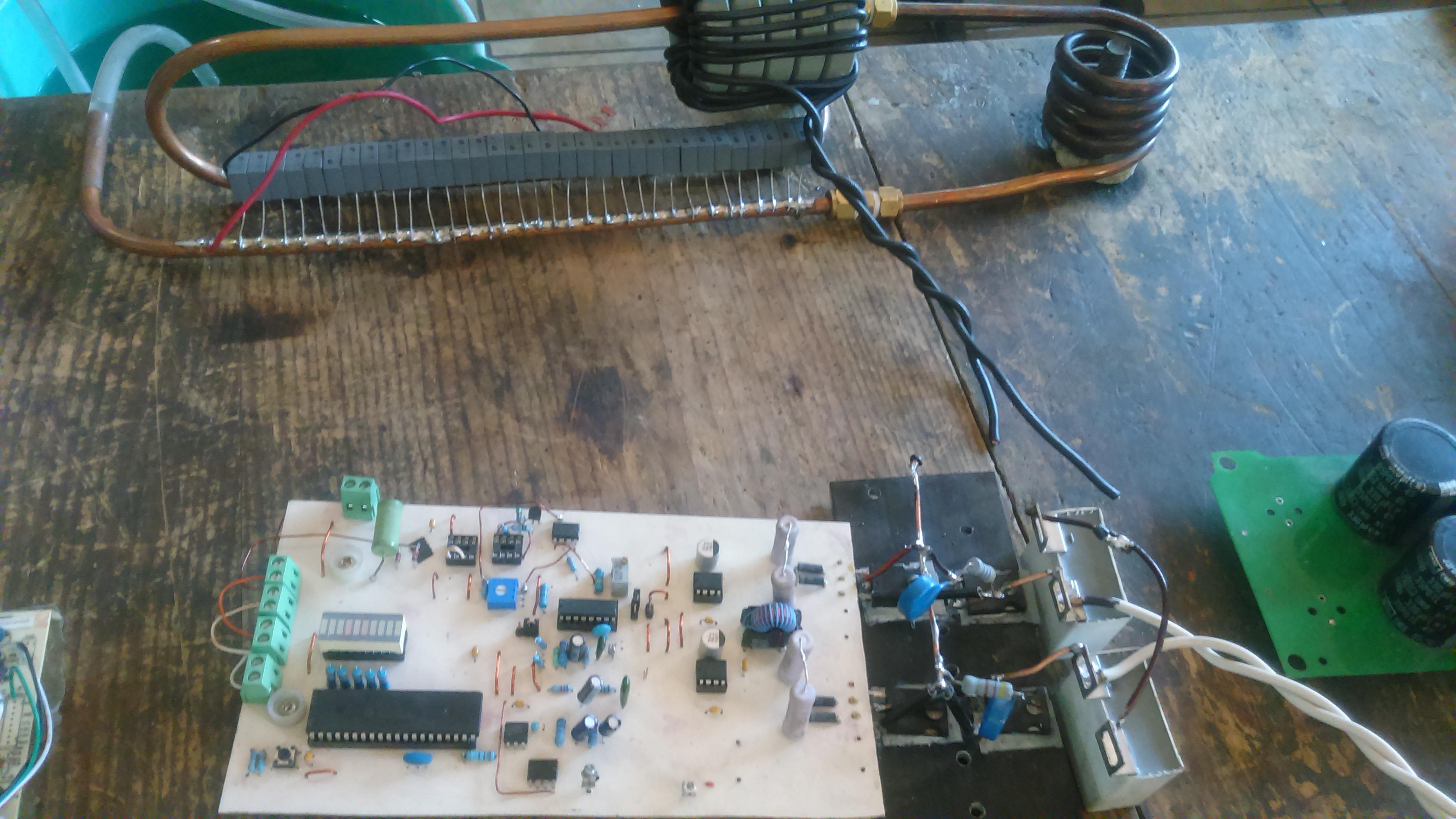
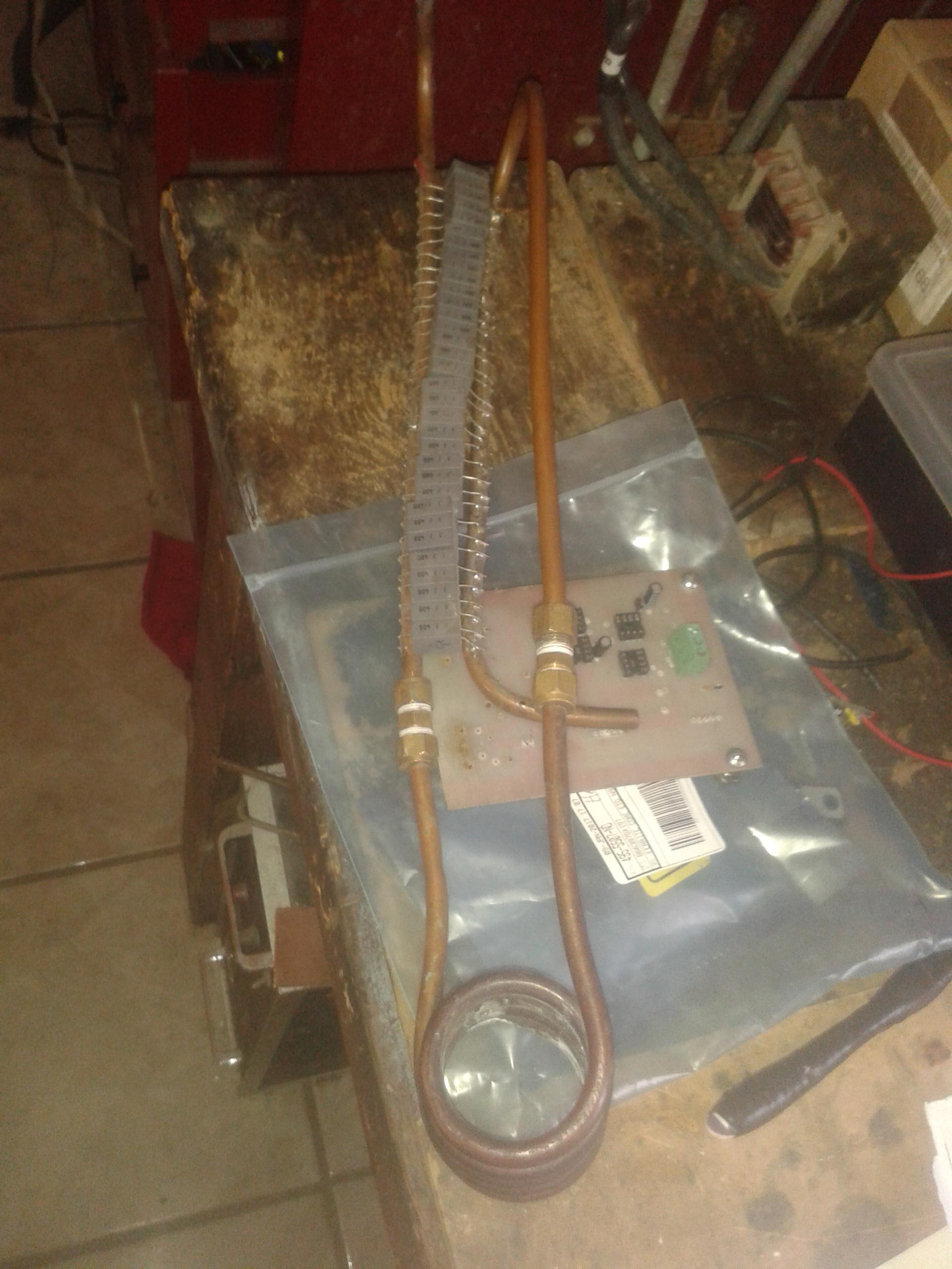
 i want oneit looks dirty but its the first version i need now a high frequency and power transfromer
 good day To power my inverter I will use a rectifier of 30 amp 800v this leftover but I do not see the problem, I need to design my tank circuit, there is too much information on the web I think of designing one with small capacitors since the capacitors for induction furnaces are expensive. And my coil will use copper tube to be able to circulate water and not be damaged. I will try to generate a resonance frequency between 80khz and 60khz ... We'll see what happens
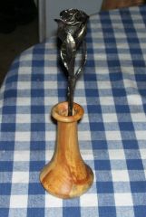 The perfect rose.... awesome


.jpg.102571a61a26e36eb188bd3bfd878aec.jpg)


Account
Navigation
Search
Configure browser push notifications
Chrome (Android)
- Tap the lock icon next to the address bar.
- Tap Permissions → Notifications.
- Adjust your preference.
Chrome (Desktop)
- Click the padlock icon in the address bar.
- Select Site settings.
- Find Notifications and adjust your preference.
Safari (iOS 16.4+)
- Ensure the site is installed via Add to Home Screen.
- Open Settings App → Notifications.
- Find your app name and adjust your preference.
Safari (macOS)
- Go to Safari → Preferences.
- Click the Websites tab.
- Select Notifications in the sidebar.
- Find this website and adjust your preference.
Edge (Android)
- Tap the lock icon next to the address bar.
- Tap Permissions.
- Find Notifications and adjust your preference.
Edge (Desktop)
- Click the padlock icon in the address bar.
- Click Permissions for this site.
- Find Notifications and adjust your preference.
Firefox (Android)
- Go to Settings → Site permissions.
- Tap Notifications.
- Find this site in the list and adjust your preference.
Firefox (Desktop)
- Open Firefox Settings.
- Search for Notifications.
- Find this site in the list and adjust your preference.