
James Bond
-
Posts
36 -
Joined
-
Last visited
Content Type
Profiles
Forums
Articles
Gallery
Downloads
Events
Everything posted by James Bond
-
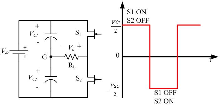
I decided to design the driver that will activate my inverter, I will start deciding which inverter I will use, I think I have in my laboratory all the elements to design a half bridge inverter, for now I will design one of half a bridge because I do not want to burn many mosfets or igbts My driver design will be able to deliver enough power if necessary to my devices, so that they can turn on or off in a short period of time, they will also have to have different sources for each power transistor. As I do not want to have noise or ringging problems in my gates, my driver should be as close as possible to my inverter. and connect a good resistor to the gate. OK I chose to use igbts instead of MOSFET I think high currents work very well and my frequency of oven work will be low so I do not see problems The inverter will have the configuration of half bridge that means that we will carry 2 igbts and two capacitors that I got from mouser I have thought to use red snubber to remove any peak but until now I will not use it
-
Thank you my dear friend for the invitation 50KW is very powerful, could you send me photos of the manual or electric diagrams of the inverter to study it? For now I follow with the design of my inverter one quite smaller than yours. And with the driver that will activate the igbts I decided to design the driver that will activate my inverter, I will start deciding which inverter I will use, I think I have in my laboratory all the elements to design a half bridge inverter, for now I will design one of half a bridge because I do not want to burn many mosfets or igbts My driver design will be able to deliver enough power if necessary to my devices, so that they can turn on or off in a short period of time, they will also have to have different sources for each power transistor. As I do not want to have noise or ringging problems in my gates, my driver should be as close as possible to my inverter. and connect a good resistor to the gate.
-
oh, ok thanks Sr
-
Regards Your project is great What material did you use to concentrate the heat in the box, and make it not warm the outside of the box
-
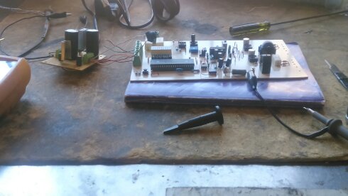
good morning I was working on a design with a microcontrol and a pll that I found on the web. I did not like that the card was so big and with so many elements but it is what there is at least in this first version Try that the feed tracks were as short as possible to the micro, I think I'm going to generate a lot of noise or harmonics when my inverter is working.
-
Digital control the head of my induction furnace ..... The induction furnace in its simplest form is a coil switched to a specific high frequency, and I say specifies because this frequency will depend on 4 factors 1 Working coil (tank circuit) 2 Our workpiece 3 Our capacitor (tank circuit) 4 Temperature Of all this will depend our frequency. Then we know that the frequency will vary by any of these four factors, The Digital Control must generate a frequency and must always try to maintain the desired frequency so that the max power is transmitted to the part, My card needs to condition signals and read data as well as generate a control in the inverter and detect signal out of pahse and I will design my card with microcontrollers and analog circuits and a PLL. There are many circuits on the web that show what I am going to do and if any of them serves me I will take it into account
-
i know but i can't begin with a 15kw heater
-
Jerry you need to follow this project. because some day i will need your help Is true but we have to create our own way please follow the project and nice to meet you
-
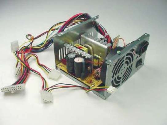
This switched source is only for powering the electronic cards and the inverter driver the power supply of the inverter will be another. The switched source for pc must be able to feed our analog and digital integrated none of these would consume a lot of current .... except for the driver for our inverter, then we will speak more clearly about this topic. As far as prices of switched sources in the market are from 19 to 25 $ to 450w I got mine from an old computer
-
First of all I want to separate my project in several steps power supply Digital control User interface Inverter driver Tank capacitor coil circuit Cooling method POWER SUPPLY is necessary a power supply that can deliver different negative and positive voltages for my analog and digital circuits that will carry the electronic card, it is important that this source can deliver several amps, this power supply must have a good emi filter and If it's tucked inside a much better metal box. The EMI filter is to eliminate noises and high frequencies that are mounted in our line socket since we will be working with circuits generating electrical noise the filter emi is necessary In my case in my laboratory I have a switched source of an old pc but still working I think it is what I need since its input has an emi filter and is high current has several voltages and is covered in a metal case Robert, nice to meet you I am interested in creating a debate on this project I have faith that everything will work out We are in touch my good friend and yes,i will add my general location
-
I will design an induction furnace of 2kw of power that will be able to reach 1000 or 1100 degrees Celsius, it will be cheap and easy to use for the user, it will be able to heat all type of metals, as long as they are small pieces, and will have the possibility of Control power. I have been reviewing and studying many home projects as well as thesis on induction furnaces and although I do not understand everything completely I think it is time to move to the experimental part.