Ed_Steinkirchner
Members
-
Joined
-
Last visited
Everything posted by Ed_Steinkirchner
-
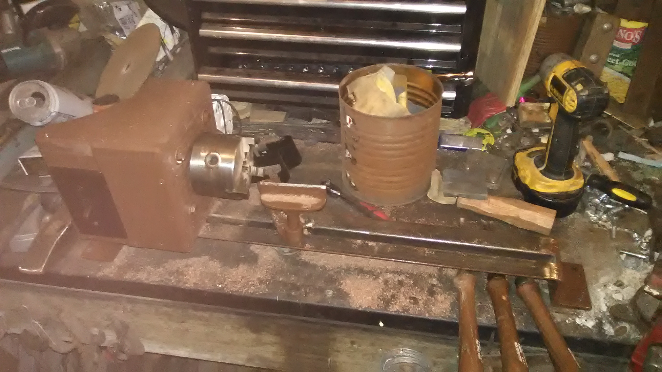
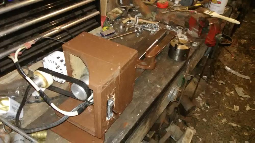
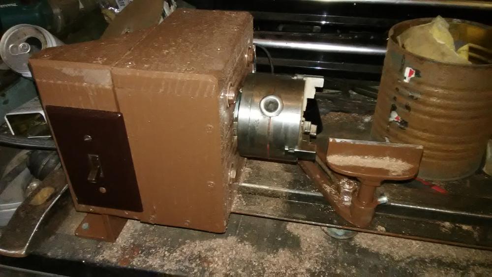
Built this little bugger in about a day. Its bed is made from two, 24" pieces of 1 1/2" angle iron, welded to an angle iron foot at each end and drilled for mounting to a bench. The headstock is made from 3/4 plywood and oak boards, the spindle is the spindle from a toro lawnmower deck that my brother's wife destroyed and he gave to me to "make something with it". It turned out that its threads were the right ones to hold this cheapy little 3" three jaw chuck i had around. The motor is a 1/20hp 1500rpm fan motor from a walk in cooler and the drive is from a vacuum cleaner flat belt between two pulleys. The headstock pulley of homecast aluminum turned on the metal lathe and the motor pulley of aluminum and a junked plastic radius arm bushing from my dads truck. It works much better than anticipated but the motor is a bit underpowered even for a machine this small. So it will be replaced in the future when i find one. Also i have a tailstock designed but not finished yet . Gotta love it when i plan comes together from the junk pile eh?

-
Sorry for not responding to any of the above questions, but my old phone wouldn't let me view ifi soon after posting this and my laptop had a real hatred for the forum as well and would let me make posts but not replies. Ive since gotten new of both and am able to post here once again! As a response to some of the above questions: It worked as it was on smal stock (up to about 3/4 square) but hit too lightly and would cause edges to mushroom. I haven't had much time to redesign it but ive upped the power to a 3/4hp motor, added a jackshaft to reduce the sleed and move the motor off the treadle, using instead an idler pulley on the treadle to act as the clutch. The original motor would bog down on the longest throw of the crank. It still needs more weight, a concrete pad poured under it to bolt to, a heavier flywheel, and a DuPont style spring assembly instead of the leaf spring.
-
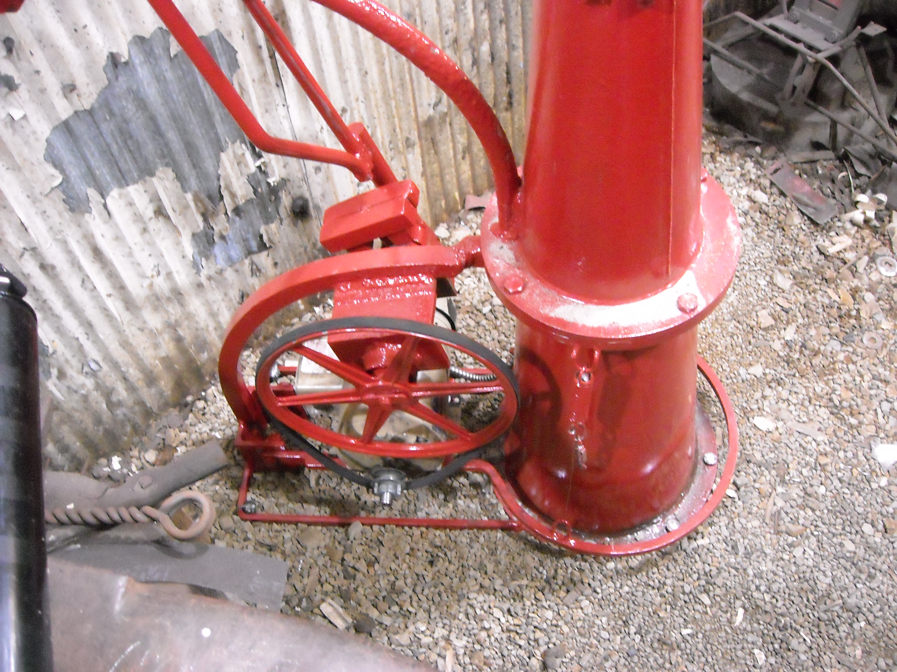
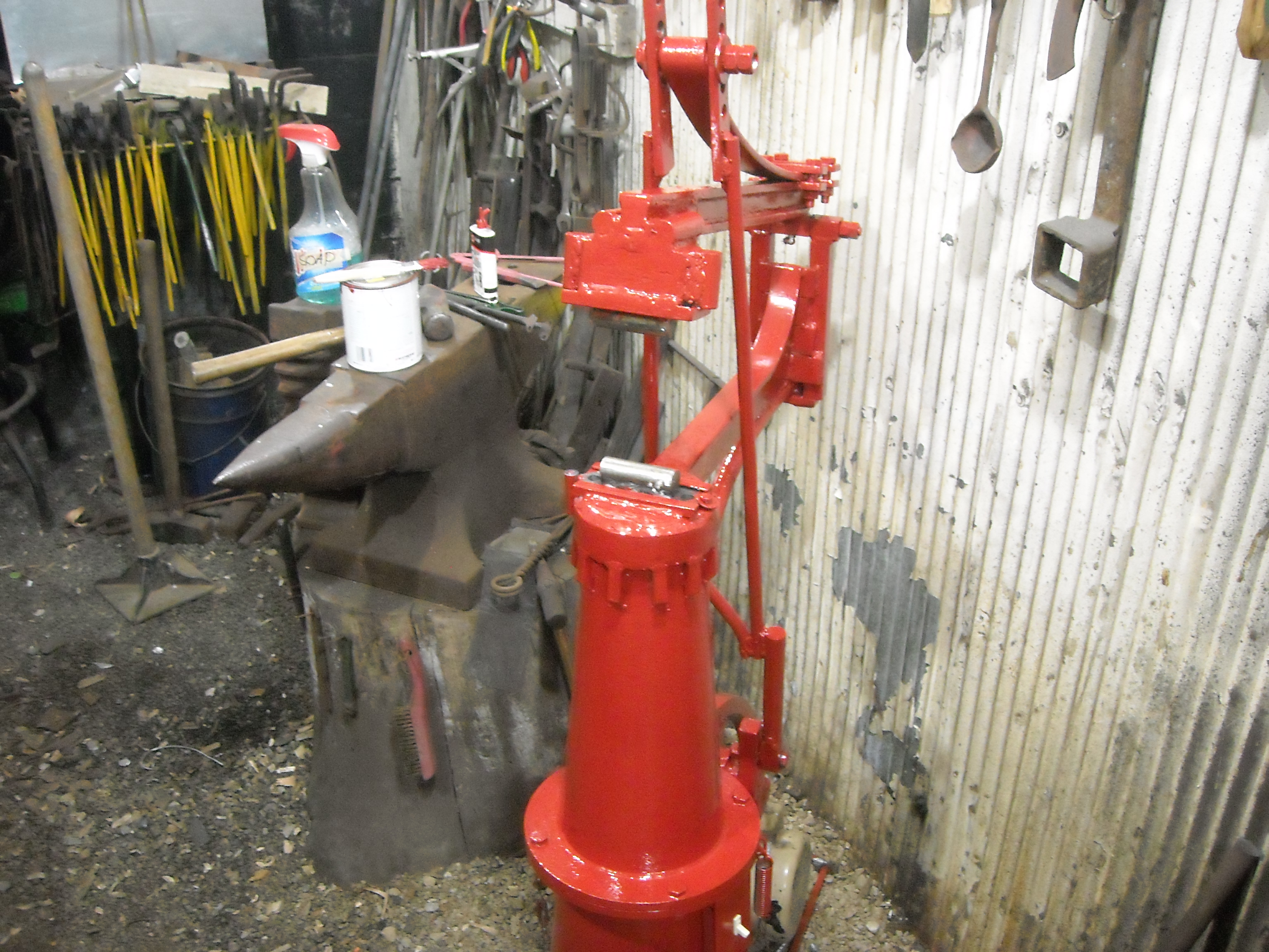
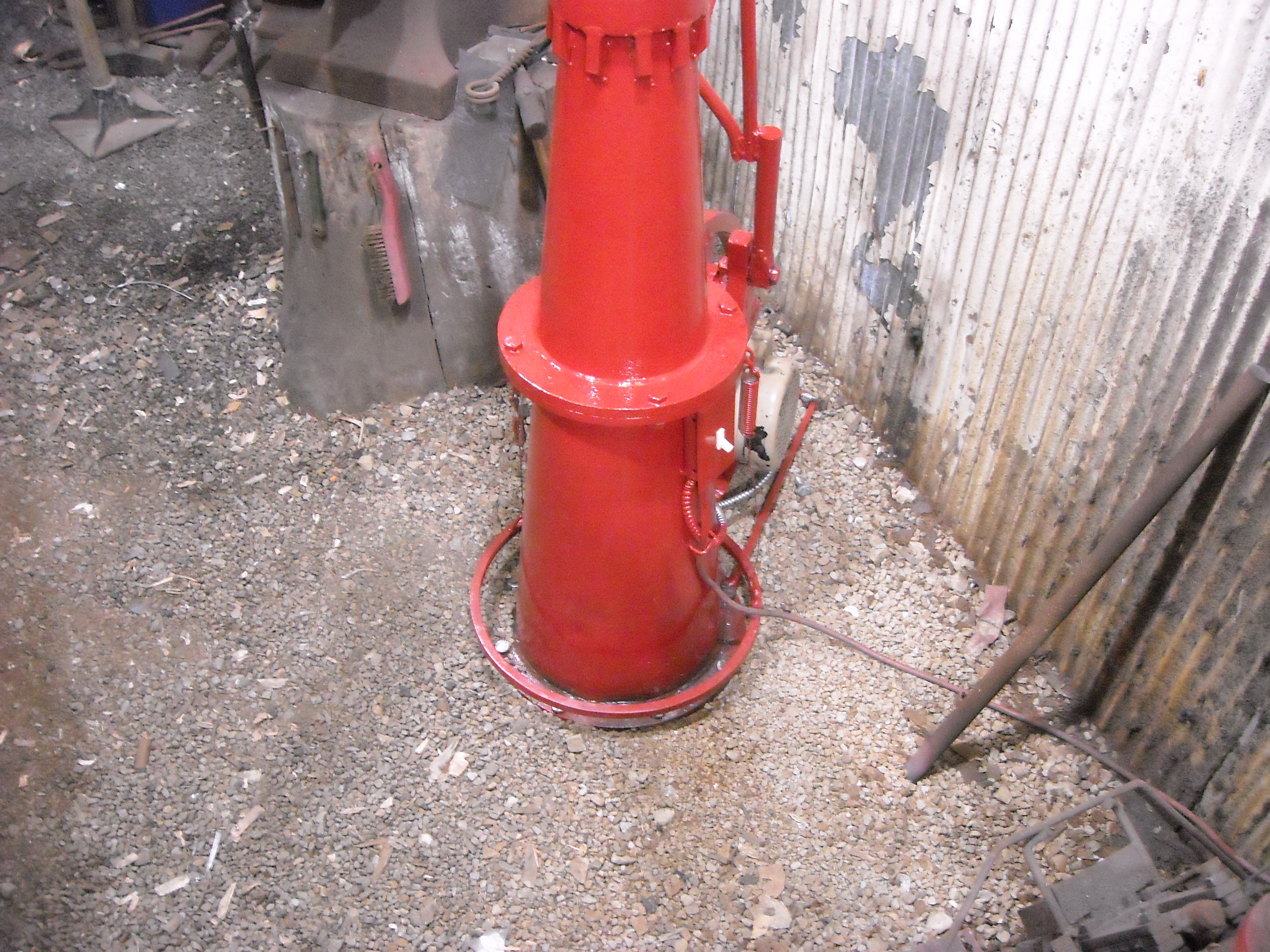
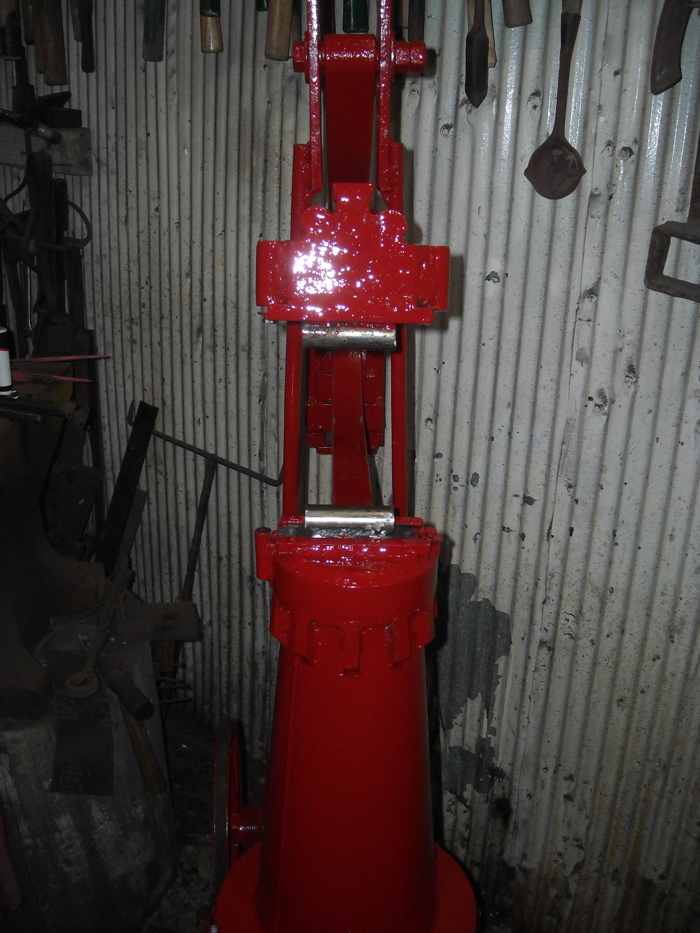
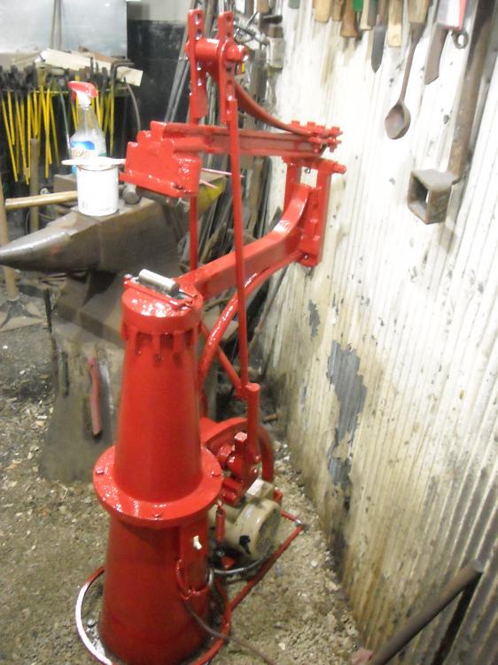
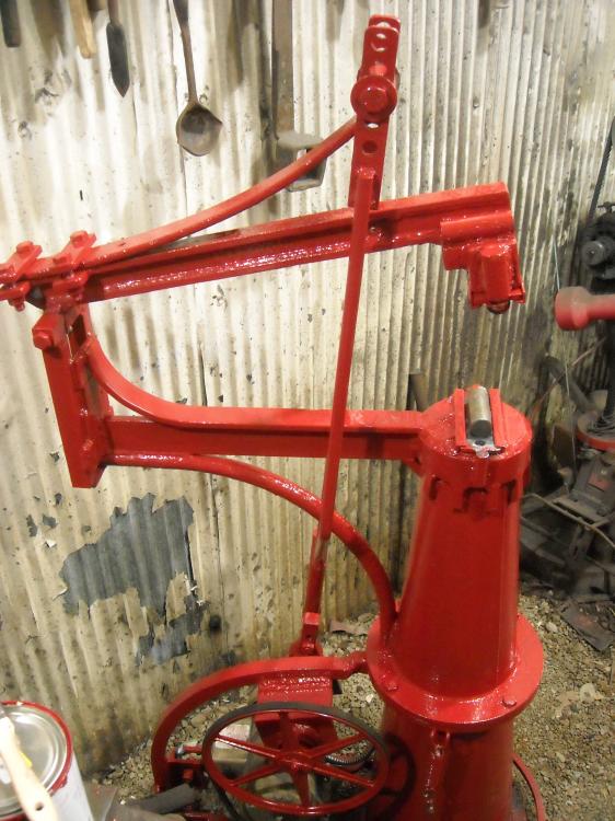
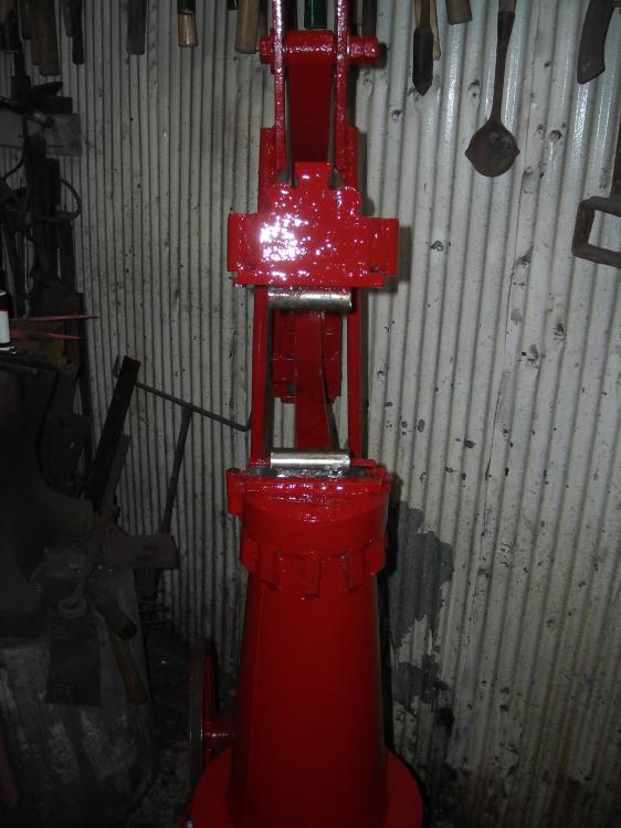
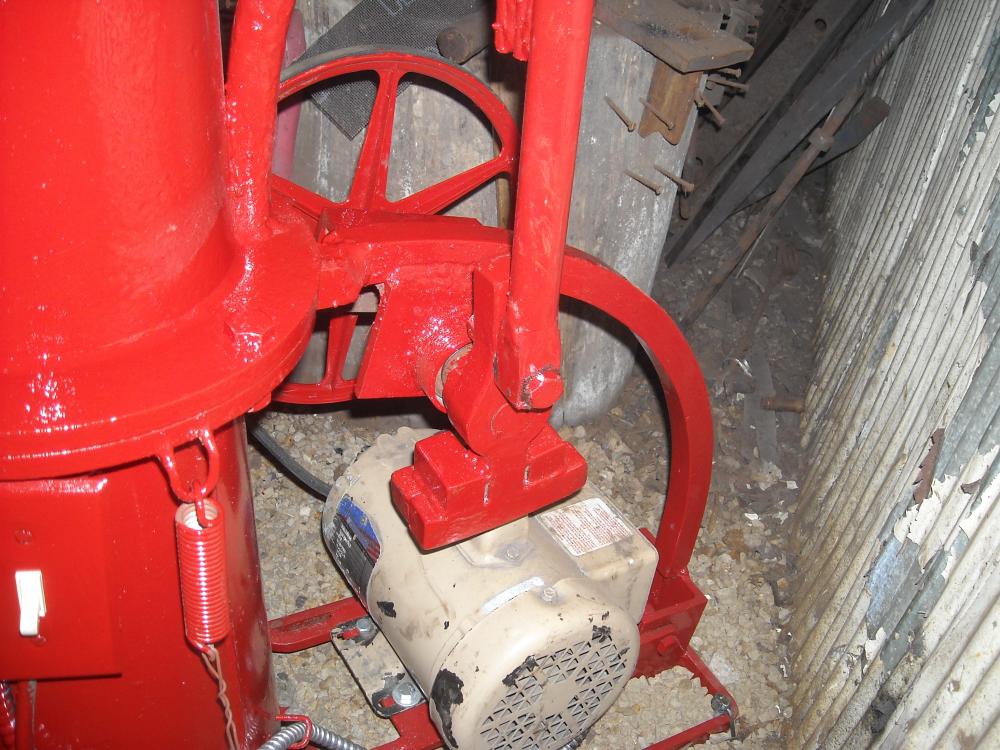
Well this has been a project that Ive been wanting to do for quite a while now and I'm glad to say it is finally finished. Its inspired from the pictures of a few compact DePew helve hammers i saw pictures of as well as the Hawkeye helve and a few others, as well as some of my own ideas. I was originally going to build a spare tire hammer but couldn't wrangle up the parts, so i looked around the shop at what i had and what space i had to work with. I still intend to build the tire hammer at some point and there are a few parts that i purposely avoided using in this build in order to save them for that project. but the most important parts here were constructed from mostly barstock. The hammer head was build of 1'' square welded into a heavier block, the helve arm from 1/2''x1 1/2'' and 1''x1/2'' bar welded into an I beam configuration, the large curved supports on the top and bottom are 1'' square and round bent cold in the bottle jack press, the treadle is of 1/2'' square, the lifting linkage is of mostly 1/2'' round, the eccentric crank is 1'' square bar welded to a heavy 1'' shaft sprocket hub from the tractor supply store, and the anvil itself (the top face at least) is of 1'' square and round alternating to leave a ''v'' for welding into a solid plate on which to mount the dies. The other main pieces are the 3/4 horsepower electric motor with a 1 1/2'' v belt pully, the 13'' spoked pulley on the other side of the eccentric shaft (set in ball bearings), the trailor spring on top, and of course the cones that make up the anvil and base of the machine. Now the cones are what inspired this all in the first place, they are two steel shells that originally lined with ceramic and were part of a coal seperation unit called a cyclone, i got them where i used to work. The cones are relatively thin though at around 1/8'' thick which made reinforcements necessary at the anvil end. The flange was torched off of the "point" and a slice of 6" OD pipe tacked into place, then pieces of 1'' bar were cut to fit the round pipe ID a,d tacked into place, finally small pieces of 1/2'' square bare were welded under the ring to spread the impact load more evenly around the cone. A few final things to note: the dies are removable and interchangeable as long as nearly the same weight is maintained (so as not to affect the tuning), the spacing of the dies is adjustable by moving the bolt in the spring shackle into a higher/lower hole, the crank offset is also adjustable by moving the crank bolt into one of three holes(1 1/2'' offset, 2 1/2'' offset, and 3 1/2'' offset) though the machine is tuned at 2 1/2'' offset (5'' throw overall) and the motor isn't quite strong enough to run it at the widest offset, and the smallest offset is really there for planishing and optional sheetmetal work. And for those who are wondering, the "Clutch" is just the motor itself being mounted on the treadle so that when depressed the motor moves down slightly which tightens the belt and engages the hammer.


-
well that makes me think though, say you had a bunch of 1'' thick plate, 8'' wide on hand, cut those to the correct length and stacked 8 of them, then welded the edges together before putting the actual die mounting plate on the top. Would that work as though it was a solid 8x8 block of steel? because then there is no parts moving around to absorb or dissipate the force being put into them, same question goes for a stack of, say 40 ea. 1'' plate discs 9'' in diameter stacked and welded into a large block just tossing that possibility out there