deker
Members
-
Joined
-
Last visited
-
Tom, I understand your position completely, and think that the offer is more than a generous one. I just need to figure out how many liquor stores I'd need to knock over between here and there while bringing you the hammer to fund it Since this posting we've chatted some on Facebook, you sent me some documentation, and the next thing I need to check for is a shot seal in the cylinder since it's blowing by at idle. Of course, having identified that this hammer wasn't actually built by you, I'm not sure how much good all of that would do. I'd love nothing more than to get this hammer down to you and get her fixed up right. I just need to figure out how to afford it right now. I figure that with freight charges I'd be looking at near $3k to get it done, and that's just not in between the sofa cushions right now. Trust that as soon as I possibly can I'll find a way to get you this hammer so it can get the necessary love and attention it deserves. -d
-
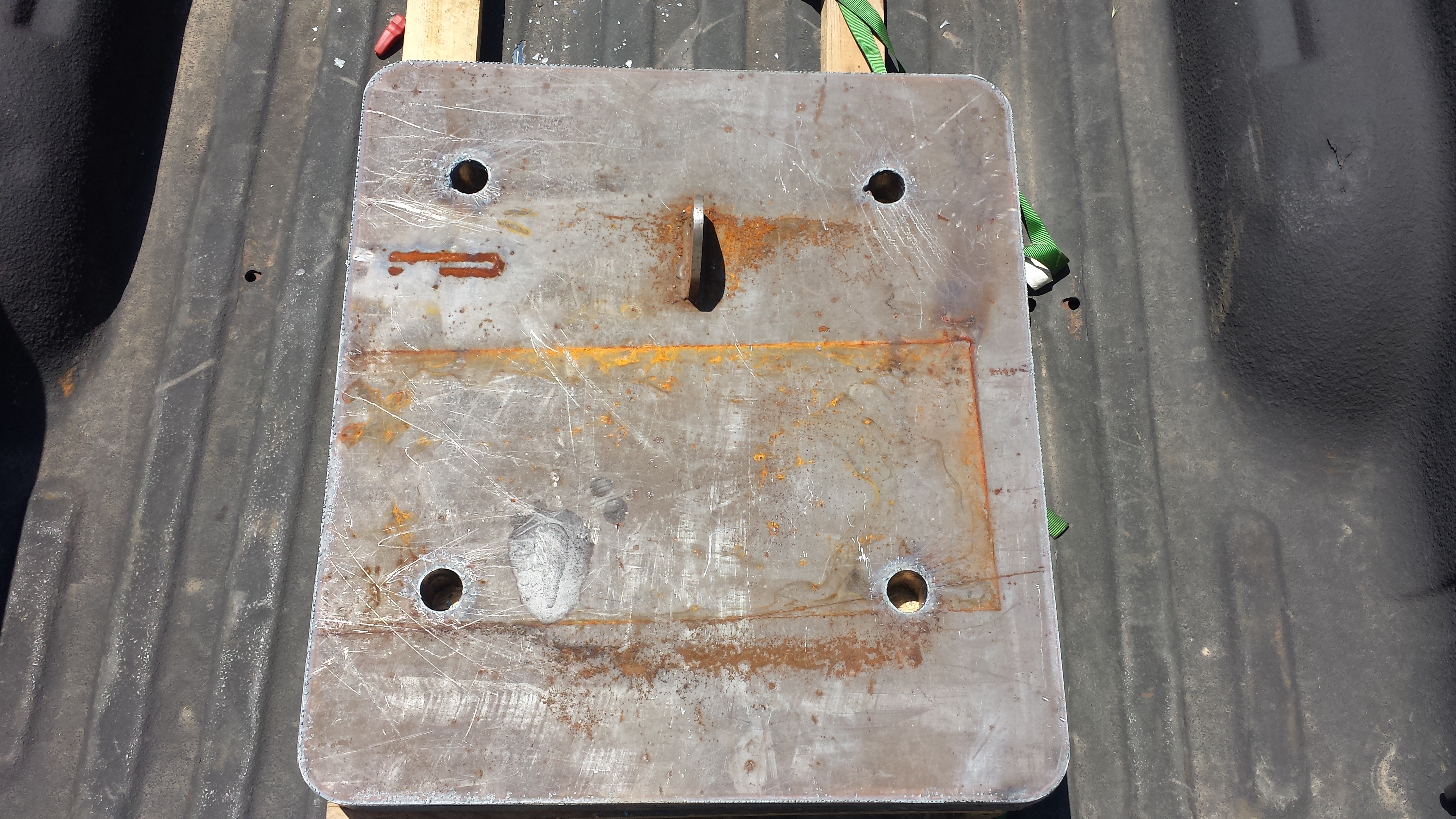
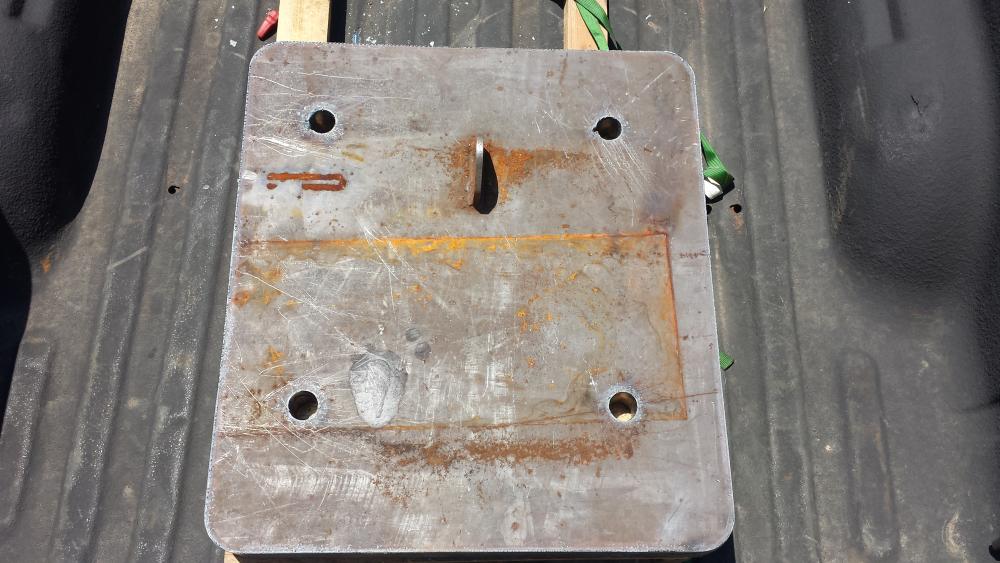
So I got a message from the welding & fab shop today. My foot plate was done ahead of the expected schedule. I went in and picked it up along with some necessary bits to make a pulley guard for the compressor and brought it all home. It's 28"x30"x2-1/4" and according to my calculations should weigh in at about 530lbs even after the holes were cut out. The lifting lug was from the previous piece, but they left it on in case it would help me with the unloading and movement around the shop (which it did, and will some more). The current plan is to cut some 3/4" plywood a little larger than the base and cut some holes for the heads of the bolts to recess in. Then I'll place the bolts and washers (7/8"x8" grade 8) through the plate, lay the plate down on the plywood and screw some pieces of angle iron to the plywood as an extra measure to help keep the hammer from walking. After that's all set in place I'll cut the lifting lug off and set the hammer down over the bolts and lock everything down. With any luck that bit will be done tomorrow and I can get the final adjustments on the hammer done so I can put the shop back together and get to work! Oh, and I'll fit welding up the pulley guard for the compressor in there somewhere as well... It's been a longer road than I had hoped for, I've noted a few mistakes along the way (can't put the top cover plate back on the hammer now due to the new throttle valve configuration...), but overall I'm pleased to be seeing the light at the end of the tunnel and looking forward to putting the Bull to work.
-
I'm guessing that the oil mist is just a by-product of the port being open, not really supposed to DO anything. I'm more wondering why the port was left open from a functional perspective...It's the curse of an inquisitive mind!
-
Thanks. So that bottom rear port on your hammer mists the linkage with oil as well? I plan to read up on that valve, review all the plumbing, and see what the intended effect of leaving that port open is. I just can't stand to leave well enough alone once I start tinkering.... I completely understand the fluid nature of improvement in small shop systems...I'm just hunting for a baseline right now. I think I'm just about there...I should have the new 28'X30"x2-1/4" base plate sometime next week so I can get the hammer fixed in place to properly tune and get to work. Thanks!
-
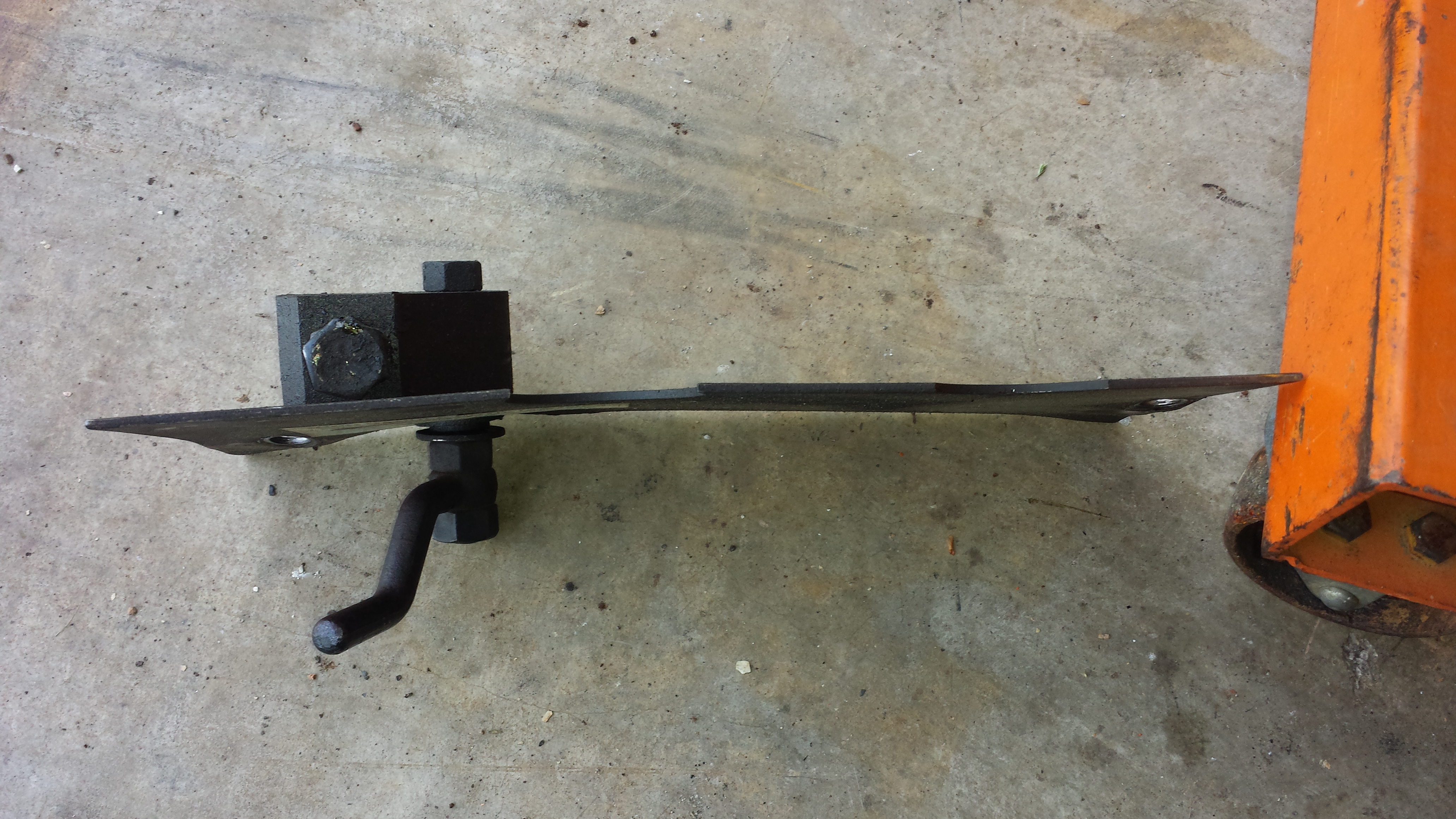
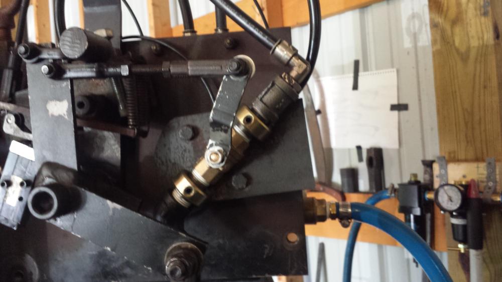
So, I went out to do battle with the ornery Bull again today. After reworking some adjustments, I had things ALMOST working right, but the slop in the throttle valve/valve arm really seemed to be the issue. Upon disassembly, I found that the threaded stem that the valve arm attaches to was almost completely stripped (likely due to being laid down and having the throttle arm get mashed). It looked like the only modification to the throttle valve was it being welded onto the mount and a custom arm fitted that operates 90-degrees out of the norm for a ball valve arm. So, I went off to the hardware stores to see what I could find. There was not an iron bodied ball valve to be had anywhere, so I had to make do with brass and build the new mounting setup pictured below. a full-flow 1/2" ball valve (the stock one was 3/4", but only had a 1/2" orifice), some 2" pipe nipples, a 1/2" pipe coupling, and a couple of 7/8" shaft collars were mounted onto a piece of 3/8" scrap plate I had in the shop. I re-used the original valve arm after a few swipes with a file to make it fit the new valve. So far everything looks much better. I still have some adjusting to do. In no-clamp mode the tup returns too vigorously. This is likely due to some needed tweaking in the throttle link and the set screw on the clamp lever block. I once I make sure everything is good, I'll have to disassemble again and put the proper final welds onto the shaft collars to make sure that they stay secure. I will also need to really get moving on the extra base plate since the hammer seems to hit MUCH harder now and started to hop itself across the floor (especially with the tup flying back to top). Only one question left. Does anybody else's hammer have an open port that vents air/oil on the bottom right of the roller valve (as you look at the control side of the hammer)? Mine does and I wonder if it's supposed to do that or if I lost an 1/8" plug somewhere along the way.
-
Thanks metalmangler. It's good to know that some slop in the controls is a nominal "normal" state. Any idea what modification might be to the throttle valve (aside from welding it to a mount)? I can pull it off and see if I can figure it out, but any pointers will save headaches... I noticed on the side of the roller valve facing the paddle pivot that there is one port at the bottom left open that sometimes leaks air (and oil) during operation. Is this correct or am I missing a cap or hose? Also, what are you folks using for mufflers? There was what looked like a small engine muffler attached to a piece of hose, but the muffler got crunched in the move. I'm considering just doing what John Larson does with his Iron Kiss and just running a piece of hose into a bucket full of lathe swarf and capping it with a top that has some holes drilled in it to vent. I have a bucket of lathe swarf already that would work well, but I'm always willing to hear other better ideas! Thanks, -d
-
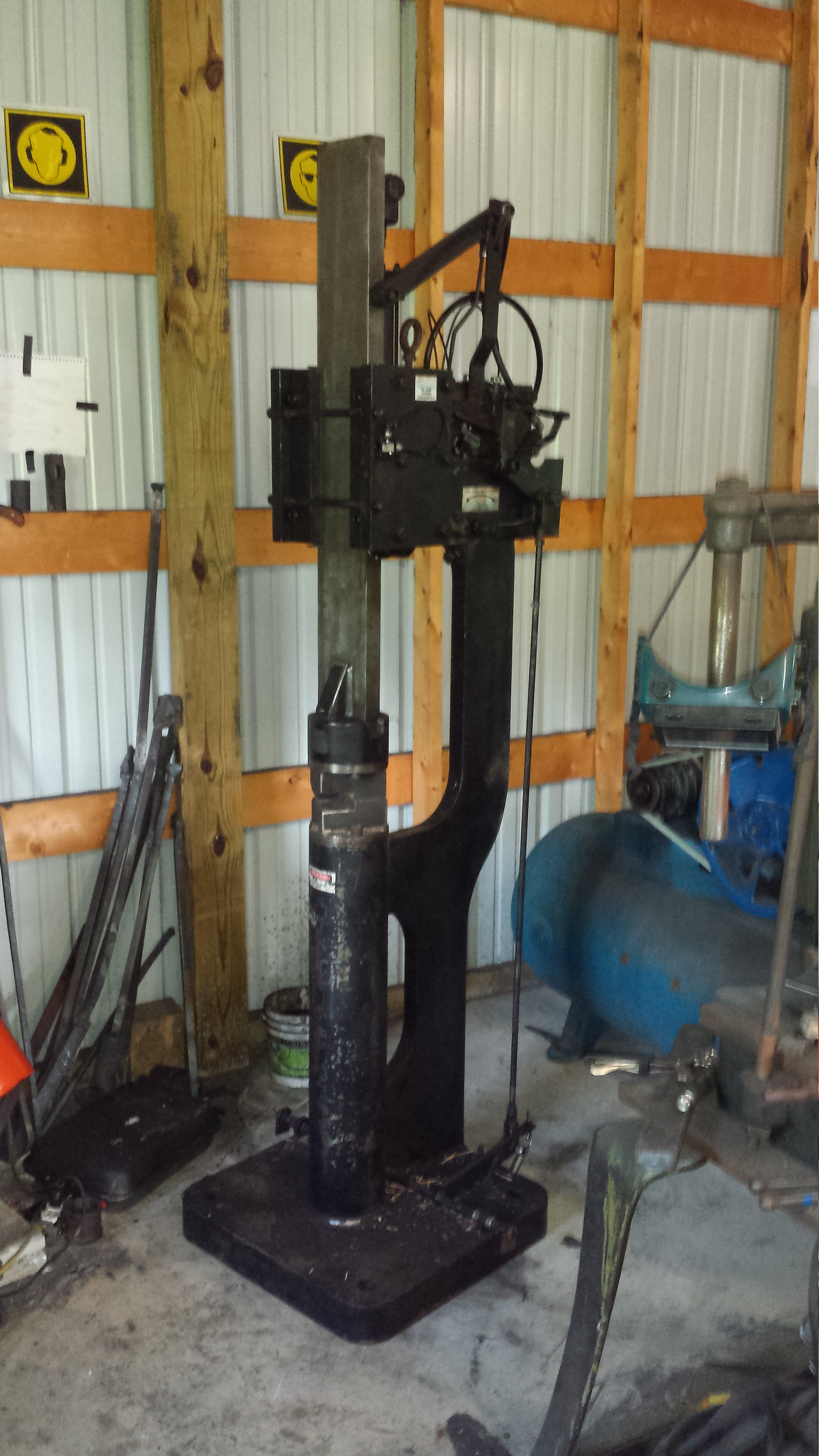
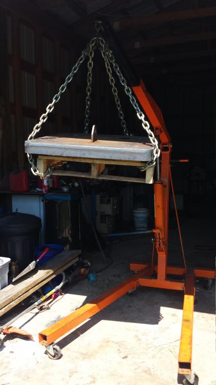
Thomas, I stopped at my local welding and fab shop and they have a piece 2-1/4" thick that's scrap that they'll sell me at scrap price. I'll have to pay an hour or so of shop time to get it cut to the size I need, but that's probably worth it to get the exact size and shape I want. It even has a lifting ring welded to it already so I can move it around easily and cut the ring off once I get the holes drilled. Then I just need to find a mag drill I can borrow or rent to get my drilling done. It may be a few weeks to keep costs down since their big plasma table is currently set for cutting thinner stock, next time they adjust it for thicker stock they can do it. I'm in no real hurry, so that's fine for me. I did play "shop tetris" today to get it into its new spot. Once I move the anvil back and find a place to store the Kerrihard I can start to run the hammer a bit and get it dialed in properly. Here's a picture just for the fun of it.
-
I did a little more tinkering with the hammer today and I'm getting much closer. I stopped and looked at what the various adjustments do and managed to figure out the following: The relationship between the offset arm and the paddle contact is very important to the adjustments of the clamp mode and having the tup not auto cycle at rest I shortened up the offset arm a bit, which allowed for a change in geometry of the paddle/valve relationship with the hammer at rest. So, I was able to stop the auto cycling and still keep the paddle/valve geometry for clamping I think that there may be something wrong with the throttle (exhaust) valve. It right in the area where the hammer took a beating and the throttle arm was loose when it arrived. I tightened it, but there is about 15 degrees of play in the valve before it affects airflow. This really makes dialing in the needed airflow difficult. The throttle valve needs to be SLIGHTLY open to keep the tup at the top when the hammer is at rest The geometry of the throttle arm to the combination lever seems to be not very tolerant of slop in the valve/valve arm I adjusted the tension on the treadle return spring so that it "snaps" up with more force. It wasn't QUITE returning all the way up and this seemed to help things a bit. There is still some air blow-by with the tup at the top of its travel with the hammer at rest. I think that this MAY be due to issues with the throttle valve, but until I get a little more info about how the throttle valve is SUPPOSED to work, I can't be sure. So, a couple of questions (mainly for Alan I guess, but anybody else who knows, please chime in!): Should there be any slop in the throttle valve/valve arm? Is there anything special about the throttle valve, or is it just a ball valve welded at the right angle? It seems that the alignment of the throttle valve arm isn't what I'd call "normal" for a ball valve, but since mine got banged up, I have no frame of reference. Do other bull hammers blow by a bit of air at rest? The documentation seems to indicate that it shouldn't, but if the throttle needs to be open to keep the tup up (which it seems to need on mine), I don't see how it could operate without some leakage. Of course, if a cylinder seal is leaking, that would also explain the issue. Seeing as a leaky cylinder seal is a possibility listed in the troubleshooting section of the manual, I fear that I may have an issue with the cylinder...I REALLY hope not. I feel like I'm REALLY close now. I could use the hammer in the state it's in now, and likely will once I get a propane refill to test things out. I have to lock down a few fasteners/jam nuts where I've been fiddling, etc. I hope to give it a test run in the next day or so, but that necessitates moving it into the forging area so I have to rearrange things to move a 750lb bandsaw out of the path of travel, move my anvil, remove my Kerrihard from the forging area, move a 500lb welding table to put the compressor where the table sits now, and get the hammer into the spot currently occupied by the Kerrihard...Ok, maybe not tomorrow, but I should be able to knock out the necessary equipment movement tomorrow if nothing else. Thank goodness for my crappy Harbor Freight engine hoist! I also need to think about the foundation for the hammer. I know that a 12" thick concrete pad separate from the rest of the floor is ideal, but I don't know that I can reasonably do that right now since things are likely to get rearranged a bit until I find the right spot for the hammer. I'm contemplating putting a piece of 2-1/2"x24"24" plate under the hammer to add the additional mass recommended by the manual, but I can't likely afford that expense right now either. I'll be checking what that would cost tomorrow. I'll have to pay the local welding shop for some hole drilling, etc as well as I don't have a mag drill or any machinery capable of holding a 400+lb plate of steel to drill the necessary holes (not to mention that without holes to use as lifting points, I couldn't move the xxxxxx thing if I brought it home...). What are the rest of you doing for foundations? -d
-
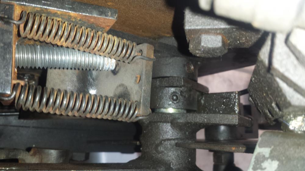
So, I spent a little time today trying to adjust the hammer according to some documentation I got from the previous owner. It seemed like EVERYTHING was way out of whack. Here's what I've done and where I am. Removed and straightened the treadle linkage rod Removed and straightened the bottoms side plate that holds the clamp handle After this I started in on the adjustments listed in the document linked above. Adjustment 1: The treadle setup is a bit different, but returns decently. It could use a LITTLE more return spring, but overall it seems ok. Adjustment 2: Reset the treadle link length so that the latch arm returns to 12:00. No big deal here. Adjustment 3: This was nowhere close. I adjusted the end of the offset link as described. Adjustment 4: Again, this was nowhere near right. I had to adjust the paddle adjustment set screw way down to get the 1/8" of described clearance. Adjustment 5: When given air, initially the tup didn't rise at all A bit of counter-clockwise twist on the throttle lever and it started to come up. I also noticde that the throttle lever was a bit wobbly, so I removed it, tightened up the back but, reinstalled the lever, and tightened the outer nut. A little more counter-clockwise twist on the throttle lever (with the link flipped back) and the tup rose and began to cycle. No problem, I'll adjust the paddle set screw back...a lot...until the tup quit cycling. I had to back it off enough that adjustment 4 was probably no longer good, but I'll move along, maybe something in the last adjustment will normalize this... Adjustment 6: Haha! Can't follow the instructions here because the tup wo'nt clamp because of the difference between adjustments 4 and 5. Couldn't proceed. So, I poked around a bit and noted that the roller valve mount had some movement I hadn't noticed before. It seems that it will rotate slightly on the shaft. The set screw was a bit loose, so I tightened it, but it still rotates. Here's a video showing this. This of course means that there is variability in the clearance between the roller valve and the paddle, so I can't see how it should be possible to make both adjustments 4 AND 5. Even when holding the valve on the downward side of it's wiggle, the two adjustments are nowhere near each other. The paddle return springs seem good and string as well, so that's not really factoring in as far as I can tell. I also noted some side-to-side wobble in the ram link assembly. Here's a video of that. I snugged up the set screw on that collar and it still wobbles... There's a bit of space between the roller valve mount and the piece next to it that's closer to the outside. Here's a picture of that: So, Alan, or somebody else with a bull, can you take a look at your hammer and tell me how much (if any) play there is in the roller valve mount and the ram link assembly? I don't want to dig into tearing all of that apart if this movement is intentional (if nothing else, I'll have to go find/buy a hex wrench large enough for the giant cap head screw that was used as the shaft here... I also noted about 10-12degrees (eyeball estimate) of rotational play in the throttle valve. Is it trashed? The handle was right in the line of fire for whatever bent up the lower cover plate, so it wouldn't surprise me... I've made progress, I can get the tup to cycle with the treadle, but the throttle really needs adjustment as it's moving up way too fast. Any help or suggestions are GREATLY appreciated. -d One other note...There is some air leakage out the exhaust when the hammer is at rest. It's variable based on throttle level position, but according to the docs from Alan, this may mean an internal leak in the cylinder and the only instructions are "Call us"....Any ideas here?
-
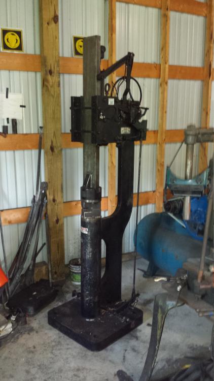
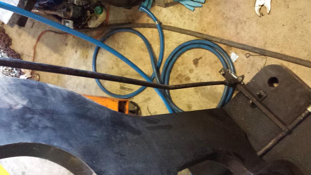
Alan, Thank you for the scan of the manual! It will likely make my life a lot easier. The main roller valve is fine, it was the "switch" valve on the front of the hammer that had an issue. I've since discovered that this is intended to be a quick way to engage/disengage the clamping feature. Seeing as There is also a mechanical way to do that, I just bypassed the switch and the hammer reciprocates now. I have to remove and straighten the bent treadle linkage and side plate that holds the clamp feature handle (pictured below) and probably readjust everything to get it tuned in. Sadly it will probably be next weekend before I can get to that since I'm traveling this week for work. I've got 1/2" filter/regulator/oiler right now and need to recover from the hammer purchase a bit before I can upgrade all of that and the hose. Large bore, high pressure FRL gear gets a bit pricey. That said, the gear I'm using now has been running this hammer for years without issue so I'm sure it'll work OK if not at top performance until I can afford to upgrade the FRL setup. Hopefully the next post will be with a video of the hammer running! (Ok, being realistic, I'm sure it will be asking for help in tuning... ) -d

-
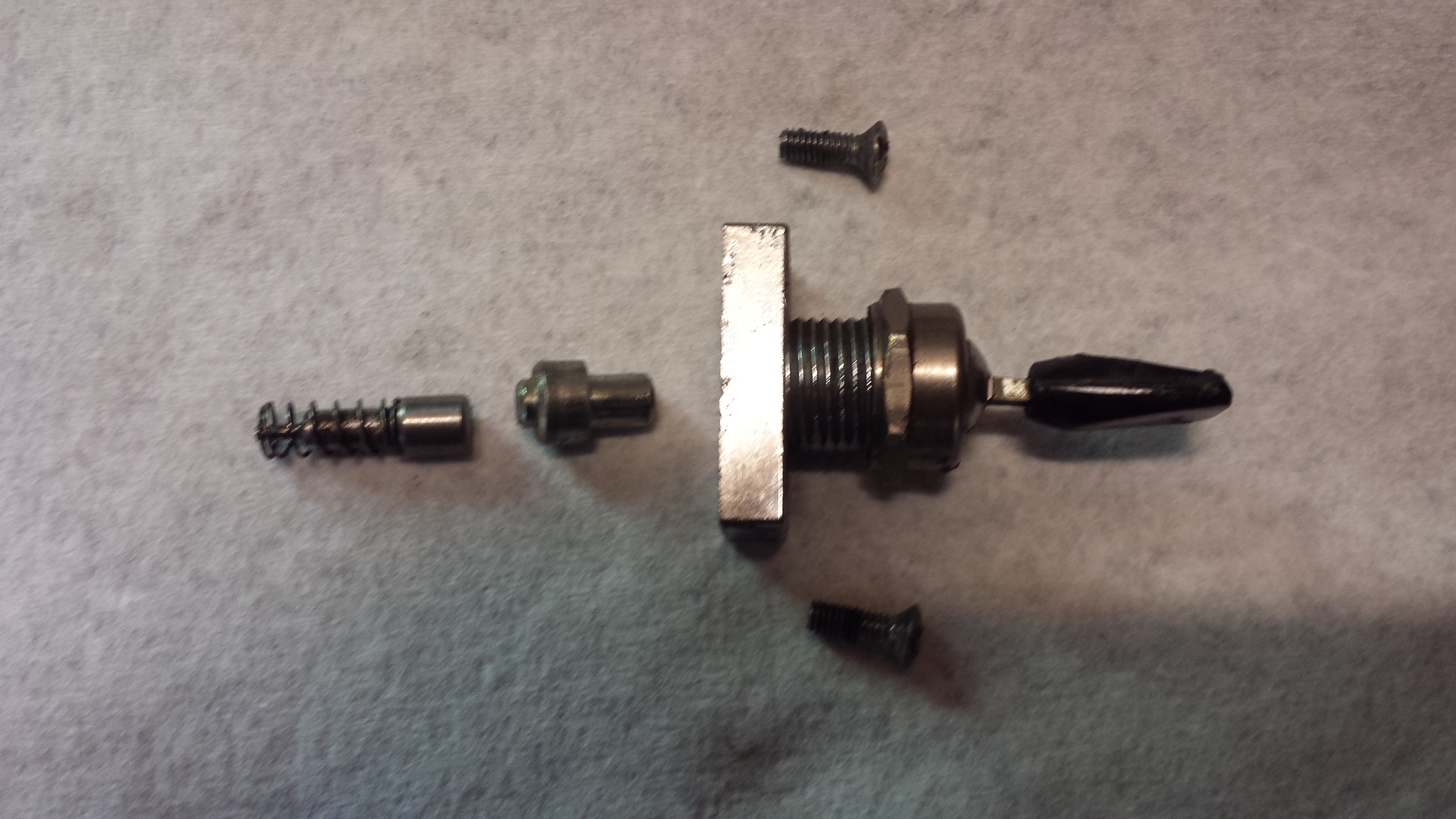
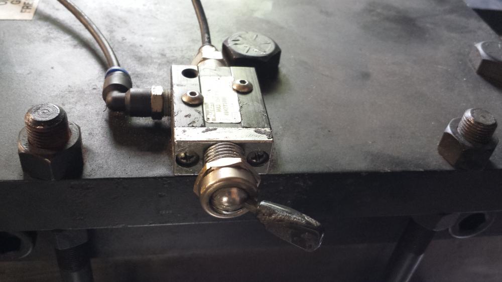
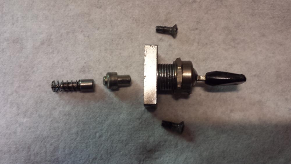
Thanks Alan! I got the hammer home yesterday and have a few issues to deal with it seems. I had some "help" getting it moved from VT to PA and then I picked it up from PA. They were moving the bull and a 75# Fairbanks in a dump trailer and laid the hammers down to keep the center of gravity low. Well, a few things got a bit knocked around in the process. The treadle linkage rod is bent (not that big a deal), the plate that holds the run/clamp handle is bent to the point that nothing lines up (not a HUGE deal, but pretty irritating), and a piece of the 1/8" control hose got smashed, but it had enough slack to just trim it short and re-seat it in the fitting. They thoughtfully removed the front of the "on/off switch" at the front of the hammer to keep it from getting banged up as well...I think that a small plunger piece from inside of that switch went AWOL. In looking things up it seems that the switch is a Parker roller value that has had the face replaced with a toggle-switch assembly (pictures below). When flipped, the plungers inside the switch don't seem to press in far enough to seat the needle an actually actuate the valve switch, so the hammer doesn't run at all. I added a little tiny slug of 1/4" round between the two switch plungers and at least got the tup to reciprocate, though the adjustment of the switch is probably not right with that little piece added. Does anybody know where I can find out what is SUPPOSED to be inside that switch plate? There's a picture attached with the pieces that made it to me. Alternately, if somebody knows where to source the proper replacement for this switch plate I'll just replace it and maybe the valve to get it right again. The valve is a Parker 404211000. It came with a bunch of 1/2" hose that I have it temporarily connected with, but might get some 3/4" if this isn't doing it once I get it running. Are you using 3/4" filter/oiler/regulator as well? -d A little more digging and it seems that the "switch" version of my broken valve is the 404811000. So, if nothing else $70 and a few days can make THAT part right...
-
Hi all. I've recently acquired a 125# Bull Hammer that I'll be picking up later this week/weekend and I have a few questions for the assembled experts here. I've run a few makes of utility hammers in the past, but not a Bull, and Tom Trozsak is a tough guy to get in touch with to get answers from the horse's mouth. What type of oil should I feed it? Plain air tool oil or something else? What pressure ranges should I be regulating to for different types of work? There is a sticker that says it's adjusted for 140PSI and has a max of 150PSI. Should I just stick here? What settings/linkages should I check/adjust after the hammer has been moved in order to make sure it's properly dialed in? I know that the cylinder air cushion settings are important, but have no idea how to set them properly. Anything else I should know/be aware of/fiddle with/not touch/look out for? I just got the Frankenpressor (Energair tank, Quincy head, motor from a Coleman) up and running and it should give me ~17CFM@160PSI. The current pressure switch cuts out at 160psi and in at 140psi and I don't believe is adjustable...this may get replaced if necessary to cut in at a slightly higher pressure than 140 to try and keep the pressure where the hammer wants it. I'll have the air input to the hammer set up as Filter->Regulator->Oiler; all 1/2" NPT for now. Should I look into 3/4" replacements? I'm excited to finally have an air hammer coming into the shop. It's going to make a lot of things a lot easier than it is now with just the hydraulic press. Thanks, -d
-
Glad to hear progress is being made Kerry! I can't wait to see this hammer running! -d
-
I concur. Take the cylinder in for repair. It will be loads cheaper and just as good as new. I used to have an X-Press ans as I recall it should be pretty easy to remove the cylinder. If you decide to just replace it, send me the old one and I'll properly dispose of it for you -d
-
The Celts and Vikings did quite a lot of pattern welding in their swords. It's almost certain that it began as a way to make use of higher and lower quality iron and steel together, but they raised it to high art in the 8th-10th centuries. As for pattern welded hammers, it's just for looks. That said, I like just about anything pattern welded -d