
mofokaye
-
Posts
88 -
Joined
-
Last visited
Content Type
Profiles
Forums
Articles
Gallery
Downloads
Events
Posts posted by mofokaye
-
-
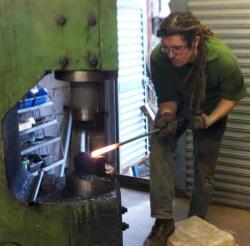
Hey Debbie, I live in Bath, and work as a smith/welder/oddjob man at a local business near Radstock. You may have seen our stall at the Christmas market. I have my own modest workshop at home, where I do the odd job, and tinker building machinery for what will hopefully one day turn into my own proper business. You'd be welcome to come visit sometime
-
We are forgetting the most obvious solution.
Buy the hammer and let it sit in your yard for 20 years.
Always a popular option amongst the Blacksmithing fraternity
-
Yep. If you want the experience of repairing that beast, then it'll be a long but ultimately rewarding one.
However, if you're after something you can use for real forging in the near future, that thing's a hell of a long way from being able to provide that. -
I would like leaks to stop appearing directly above all my most expensive equipment, so I no longer need to religiously cover everything with ground sheets every evening.
-
Somebody bidding on that probably really needs a power hammer, and is really set on the popular little giant. You don't need it...
-
I know a Blacker was the first power hammer I ever used. And in the same breath it nearly killed my by throwing it's hammer head at me. :rolleyes:
-
I was looking at that wonderful cast flywheel and was envious.
Yeah, quite a find that thing. Had to drag it nigh on two miles through an abandoned network of mine shafts to the surface. Then nearly collapsed my mates rear suspension sticking in the back of his car. Worth it though :D
-
I'm anxious to see how you assemble the spring/bumpers for yours.
Yeah I'm still mulling that one over in my head. Will probably make a start on it this weekend :D
And that is a very pretty hammer -
Aw man, now mine looks like a hunk of crap. Hahaha
-
Made some progress again today. Got the eccentric bearing done:
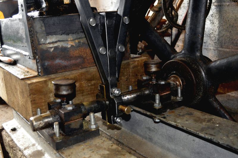
And the arms that'll transfer the motion up to the cushion/spring linkage: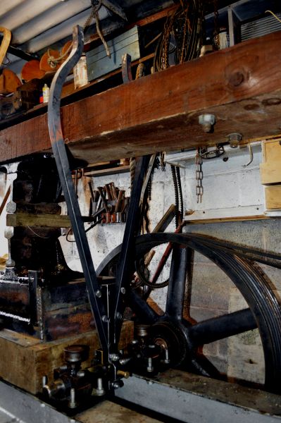
At this rate I should be taking this thing for a test ride soon! -
I like the bright red ones, very fancy haha :D I shall give that a look, thankyou!
-
Fantastic stuff, thankyou! The Morris Minor axle bumpers could be good, there's quite a few rotting away round my way.
Progress continues tomorrow, shall be making the bearing for the eccentric shaft -
It's an education for me building this thing! I've opted against the use of springs, as I had an old leaf spring from a truck go in my face once. Not pleasant at all. Instead I'm going for a Bradley style rubber cushion system. Or atleast, I'm going to try it before submitting to steel springs. As for adjustment, it'll be as simple and removing a pin, and moving it up and down a few notches accordingly. As for adjusting hammer impact, I'm confident enough hat the clutch will provide all the control I'll need. That said, this entire project is a shot in the dark, and my ideas may change as the project progresses.
-
Hopefully your government is not as stern and strict about people messing with 'abandoned' rails as ours is. The hammer looks interesting and promising.
I do have a question though... just guesstimating from the pictures, but it looks to me like your cam has about 4" of movement? is that all the movement the heads will have, or will it be adjustable, possibly by having options for how far out along the arm you attach the pushrod...?These rails have trees growing through them, believe me, the government aren't worried. :D
Once done it should have10ish inches of movement, and it'll also be height adjustable for working on larger stock. This is the plan anyway... -
Mainline trains no longer use this system, and have a more typical flat bottomed rail held to the sleeper with spring pins like this '>

However thanks to Dr. Beechings railway cuts in the 60's there are literally thousands of miles of abandoned railways in the UK... and subsequently MILLIONS of these rail chairs laying about. There may well be a profitable business here :D -
The way the rail's held in place is quite clever, but possibly no good for my uses... So some future improvisation may be in order. I'll try and show as best I can, and failing this get some decent photos tomorrow.
Here's the best picture I have: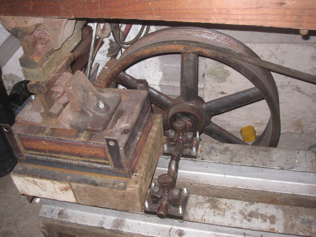
There's a U shaped spring that is hammered in behind the rail. This holds the rail in place whilst giving it a slight amount of movement to accommodate passing trains. For my purposes though I fear the rail may just bounce loose after a short period, but I'm sure I can come with something. As you appreciate, these rail chairs are just too good to pass up.
I'll see how successful they are, and if all goes well maybe we can discuss me shipping you over some ;)
As for a video, fear not, there shall definitely be one up once it's up and running! I believe there's already a link to a video from last year of just the crank running further up the thread :) -
So, it's been over a year since I made any real progress on this thing due to a heavy workload, other life commitments, and spending 2 months in a darkened room with bleeding eyeballs. Y'know, usual. But, I'm back on it now, and determined to have this thing up and running shortly. So, this weeks progress:
The anvil's done. Made out of some heavy channel, and lots of scrap round bar welded into it, it forms a formidable lump. No idea how effective it'll be, but it's the best I can manage at this time. Also you can see my use of these British rail chairs I mentioned earlier in the build, both bolted firmly in place, holding the rail track dies.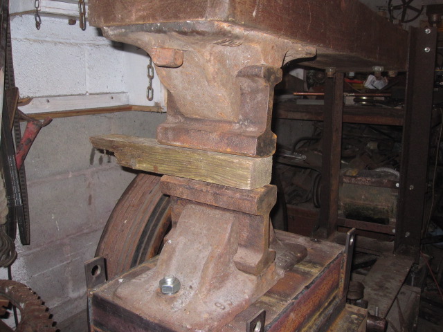
And another shot of the front of the hammer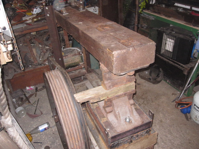
Next I attached the helve to the frame, and installed the grease cups on the brass bearings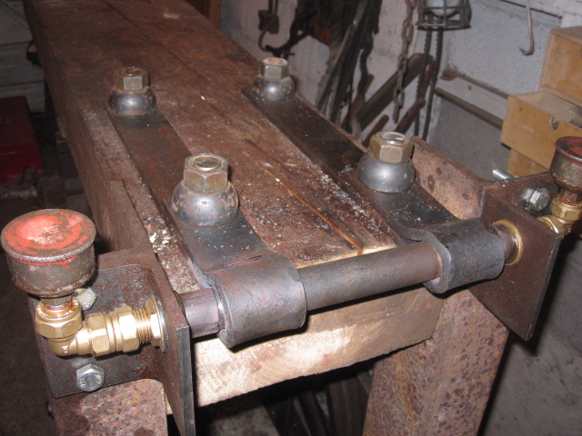
Now to work on actually transmitting power to the helve. I'm looking at using a Bradley style rubber cushion design, but will be running some small scale experiments first.
Lastly a look at the thing so far, apologies for the typical horrendous state of my tiny workshop.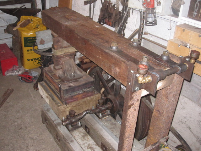
-
From Lord Of the Rings, I learned that you can just put pieces of a broken sword together like a jigsaw puzzle, pound it with a hammer, and the thing will fuse together unfluxed, way below welding temperature, without even upsetting the fuller. :P
Apparently, the smiths in that scene were the actual smiths from Weta Workshop who forged all the swords for that movie... Although in a fantasy tale involving talking trees, cave trolls and wizards, I'm inclined to assume those Elves are just far better smiths than mortal man.
-
Rammstein.
That gets your hammer moving! -
Yeah, if you look carefully those are two separate wheels on the back. One of them would be locked solid to the shaft, the other would just free turn. The belt would be part of a constantly turning line shaft, and to in turn the machine on, a mechanism was used to slide the belt onto the engaged pulley (Which is what you can see in the picture)... Hope that made sense, I'm not good at explaining things verbally... :)
-
I remember Grant said in a post some years back that the hammer in this video was scrapped long ago. I was bummed at the time I read that. :(
Hard to justify even if the whole thing had cracked in half... -
Yeah, at a quick glance I can tell that won't work well...
-
It'll be the classic slack belt clutch, the belts are just tightened at the moment so I could test the bearings, etc. The whole foot pedal assembly is next on my list of jobs :)
-
So, a few weeks later and the bearings are complete, with their own grease cups salvaged of some decaying quarrying equipment.

The flywheel is now attached (Although slightly off balance, which is something I'll address next time I have a free moment)
And the motor is bolted solidly into place.
Much more to be done, but a brief test of the crank assembly can be seen here:
Helve hammer design from 1926
in Power Hammers, Treadle Hammers, Olivers
Posted
Very similar to one I built years ago. The design works!