

jhicks2013
-
Posts
63 -
Joined
-
Last visited
Content Type
Profiles
Forums
Articles
Gallery
Downloads
Events
Everything posted by jhicks2013
-

kHy2cjd E8qii0gs2Cl7wG0QByFhY3vfpJ78a3IXGe7C GhOCF3sNn4RqXn
jhicks2013 posted a gallery image in Anvils
-
rfTihjvUE6q9uwePw8ZdNbfzBwKkLvdJ7B5J00kXz7yq Q9TCoww25Ozo S
jhicks2013 posted a gallery image in Anvils

-
zLaBhnSJHJYzTrrUfpryTbD7570Wh3KKpY6wVUa6c O4eo2bwyjr9KEtMMD
jhicks2013 posted a gallery image in Anvils
-
-
YCxGwI aY6m2ZKJpa9mrBVI8iK2ApsEWbuUpRG2ASMW3nrqiXso2YJtax
jhicks2013 posted a gallery image in Anvils
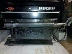
 rail road track anvil I am working on
 -
Working on a rail road anvil.
-
My next inline treadle hammer design
jhicks2013 replied to Jason M's topic in Power Hammers, Treadle Hammers, Olivers
Sorry for the misspelling I did this on my cell phone and the touch screen is acting funny -
My next inline treadle hammer design
jhicks2013 replied to Jason M's topic in Power Hammers, Treadle Hammers, Olivers
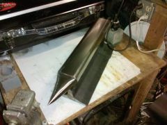
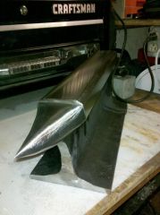
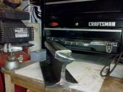
So here are a few photos that I am starting to toy around with the first photo is the hammer head. In the second photo I did a close up of the pivot linkage and you can see how the bar stock passes through the and that will allow me to adjust the arms length. The third photo is the round stock I will weld to the hammer head then below it is the bearing that will bolt to the top support arm. The fight photo is the side view nothing is is being welded I still need to sand blast all these partsi so I can weld then paint .took a photo of the bar stock witch is 1 1/2" . The last photo is an effiel geard pliuerench thought I would break up the manotony of metal it has interchangeable jaws pretty neat tool. -
My next inline treadle hammer design
jhicks2013 replied to Jason M's topic in Power Hammers, Treadle Hammers, Olivers
Hello Vaugh T, I am just entertaining the idea . Just a little of my back round I worked in a machine shop doing tig welding and and fabricating and operating cnc machines. I also was a steam fitter for a few years .For the past ten years I have been an elevator mechanic . I like a good challenge I however have the sam reserves about the strength of the linkage my linkage is 3/8"x 1 "flat stock with a 3/8 pivot I have all of the mechanical devices to make this apperatus so I wont have to shell out anything but time and just brain storming ideas . My concern is also with the travel of the ram with a rigid linkage your ram will always travel lets say 17 inches so if the space between your dies is lets say 1/2 to a 1/4 " your hammer will want to travel the full stroke , so lets say you are hammering on a 3/4" bar you will bottom out before your full stroke and put enormous strain on your pivots most likley breaking them . I like the design of the sraight line treadle better as you can have rebound and a return via springs or a counterweight . You also mentiond about the impact all the linkage will be taking and the chain and sprocket as well because this will all be conected and rigid and no chance of spring back with a continous motion so as I said I have my reserves about this design. The train drive linkage will only go to the motor and then the double drive pulley one side would be the offset pivot the other would be the chain sprocket so that point would remain the same all the time so in theroy that linkage should work. The down side is the impact this would take I believe would destroy the mechanical linkage rather fast . Now if you used the sam machine in the top of this page and did not try to go with a continuous motion and stoped when the ram hit the die, you could use a countrweight or spring to return the hammer I think it could still work . The hunk of steel I have for for my hammer weighs 25 lbs. and I plan on welding a peice of 1"3/4 chromolly solid round bar to the top of the hammer and it's polished to a mirror finish and above the hammer will be a arm with a 360 degree ball bering so this will act as my guide so I will not be relying on my linkage to guide the hammer the bar will be my guide. The chromolly round stock weighs 25 lbs and the rest of the linkage is about 25 so the weight of my ram will roughly be 75 lbs. I will also have my counter weight on an assembly attached to a similar roller bering and the cable on the weight frame will have a spring between the cable and carriage so it will isolate the impact deliverd to the counter weight. I was looking at doing a motor but think I might stick with the treadle design so I will not need power . I am looking at a counterweight so I dont have to worry about the springs streching and needing to be replaced and I can balance out the hamer better. I have the ram with the linkage already configured I havent drilled the pivots to the main post yet still looking this system over . My pivots clamp on the bar stock so I can adjust them in and out till I get them set then I will weld them in place they also are independent of each other so i have room to have a gusset go through the middle of the arms to support my arm with the bering the ram will travel up through . I have no idea the length all of these arms need to be but I can slide the pivot up and down the arm so I can move it around to get the motion I desire I will post some pictures tomorrow all of this linkage. All of this linkage is off some old elevator door closers it's really handy to work on all this mechanical stuff. But hopefully we will be able to build a system that the home mechanic can build and use and repair himself that is my end goal. -
My next inline treadle hammer design
jhicks2013 replied to Jason M's topic in Power Hammers, Treadle Hammers, Olivers
imeant to say each stroke of the petal not hammer -
My next inline treadle hammer design
jhicks2013 replied to Jason M's topic in Power Hammers, Treadle Hammers, Olivers
Awsome design i am working on making the straight line linkage #2 . For the treadle design you need to look at the way a train uses its piston to turn the wheels you could easley use the same linkage and conect the sprocket to a secondary double sprocket one going to a motor/foot pedal and the other going back up to the first sprocket.u can also use different size drive sprocket to have a faster speed with a shorter stroke if your first gear spins 1 revolution and the end sprocket spins three times you can achive three strokes from the hammer with 1 stroke of the pedal and it will be more efficent. i will post a video of the gearing to further under stand how to achive this 3 to 1 ratio.