mountmyfish
Members
-
Joined
-
Last visited
Everything posted by mountmyfish
-
Thank you for the encouraging words and the hint on where to start. I'll work on it and post back when I get there.
-
Thank you Frosty. I got a hole drilled in the bottom this morning, thanks to both you and Mikey98118 for the suggestion. Makes perfect sense. When I set out on this build I had grand visions of making super fancy doors but then read the following post from you in the thread https://www.iforgeiron.com/topic/26663-doors-for-a-propane-forge-please/ and decided not to do it: "Doors can be a pain, the fire has to exhaust somewhere and out the door is the usual. This means metal is going to warp unless you put enough refractory on and around it to shield it from the fire. I've made doors but haven't liked them much. The forge I use now I stack firebrick to restrict the openings." Has your opinion on doors vs. well-restrained stack of fire bricks changed? Perhaps "doors" above was blacksmithspeak for stack o' bricks? :-) I will say that I didn't have any trouble with 3 x K25 bricks stacked up at the back during my test yesterday. I was able to cover most of the opening, save for a few small spots where the tank curves. I was going to think about how I could make the stack less likely to fall over and/or a way to temporarily attach it to the forge while I'm using it.
-
I have not drilled a hole, as I didn't know that was a thing. I'll drill a hole there tomorrow morning.
-
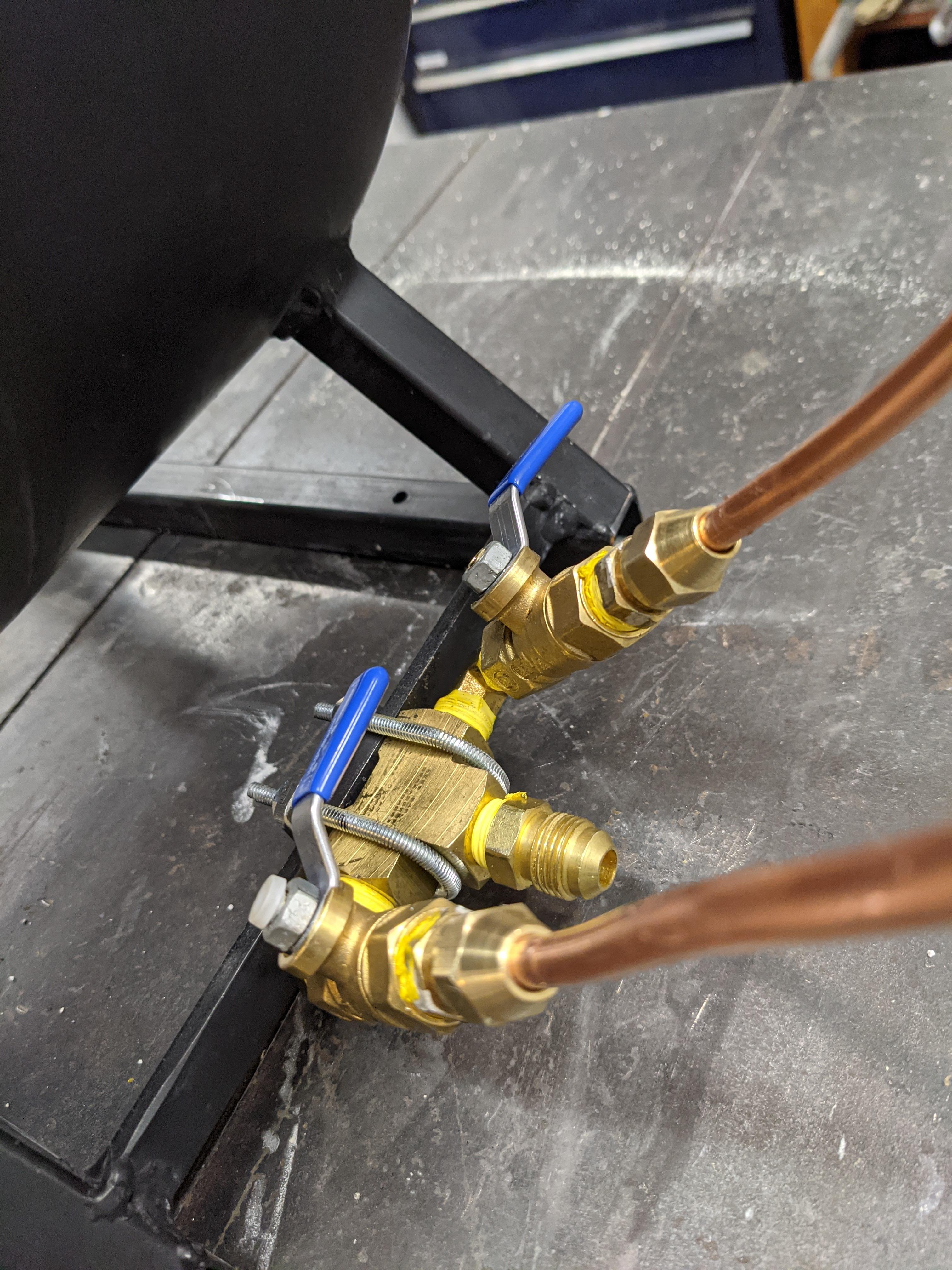
I did a few 10 minute firings and cooling off sessions today. My last one was about 1 hour with K26 bricks piled up at the back and things looked pretty good. I was using the laser thermometer to check all around it periodically and am satisfied that everything is working more/less the way I want it. The legs got up to around 120 degrees and the part touching the table was around 80 F. All of the copper/brass was about ambient temperature through the whole cycle, around 50 degrees F. The burner tubes are around 100F at steady state and the middle of the shell around 250F. I managed to get a few chunks of scrap I have laying around up to about orange (?) heat. I did buy a pint of ITC-100 because I found a coupon and am wondering when the right time to apply this is. I didn't find a post that said how many hours of fire time on the Kast-O-Lite 30 I needed to have before I put it on so figured I'd ask. In Forges 101 I found the following instruction: "For the first layer, simply coat the ITC-1-100 straight out of the jar. Heat it to stabilize it on the forge surface, and then paint on a second coat that you have first separated in some extra water. Here's the deal; the active ingredient in ITC-100 is zirconium oxide. BUT, the amount of re-radiation zirconium gives off depends of the particle size in its coating. Mixed into enough water (a couple of inches in a water glass) the crude particles will separate out of solution, sinking to the floor; the rest is colloidal particles; as in super small, which re-radiates over 90% of the heat that falls on the coating." Is this still the recommended way to go? Before the "heat it to stabilize on the forge surface", how long should I let it dry (i.e. how short is too short and long is too long)? Really looking forward to getting started hammering on hot metal after thinking/reading about it so much.

-
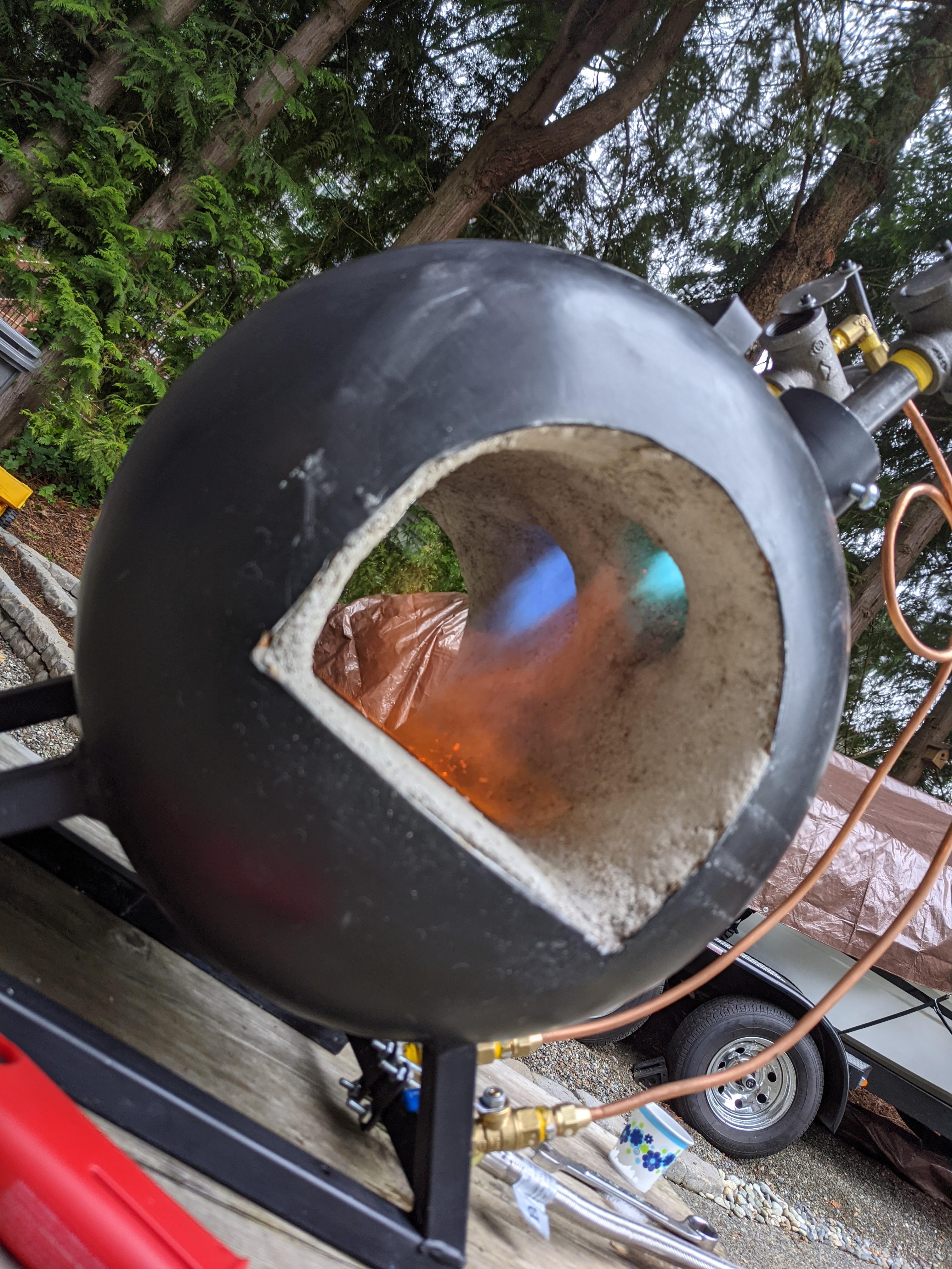
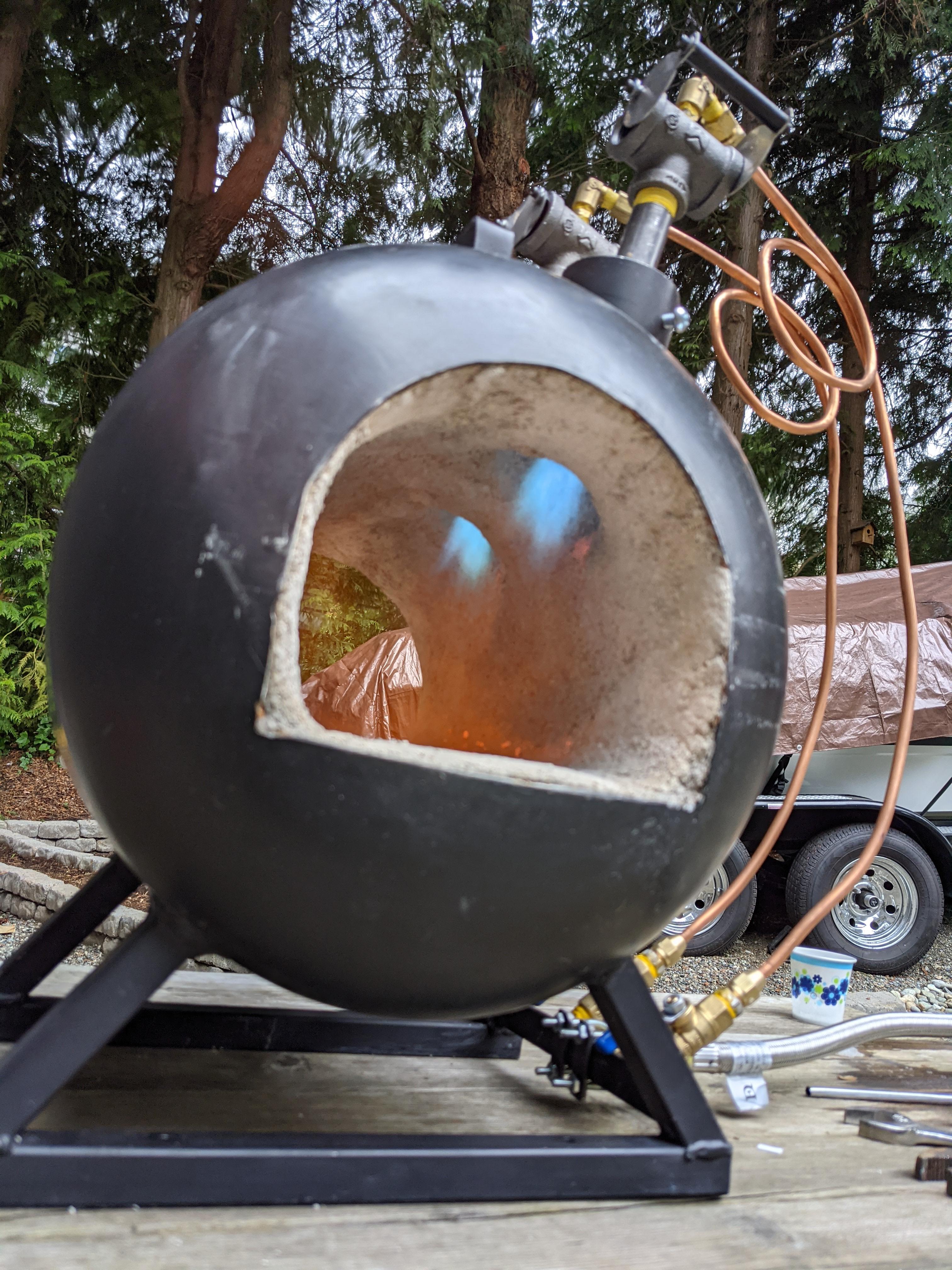
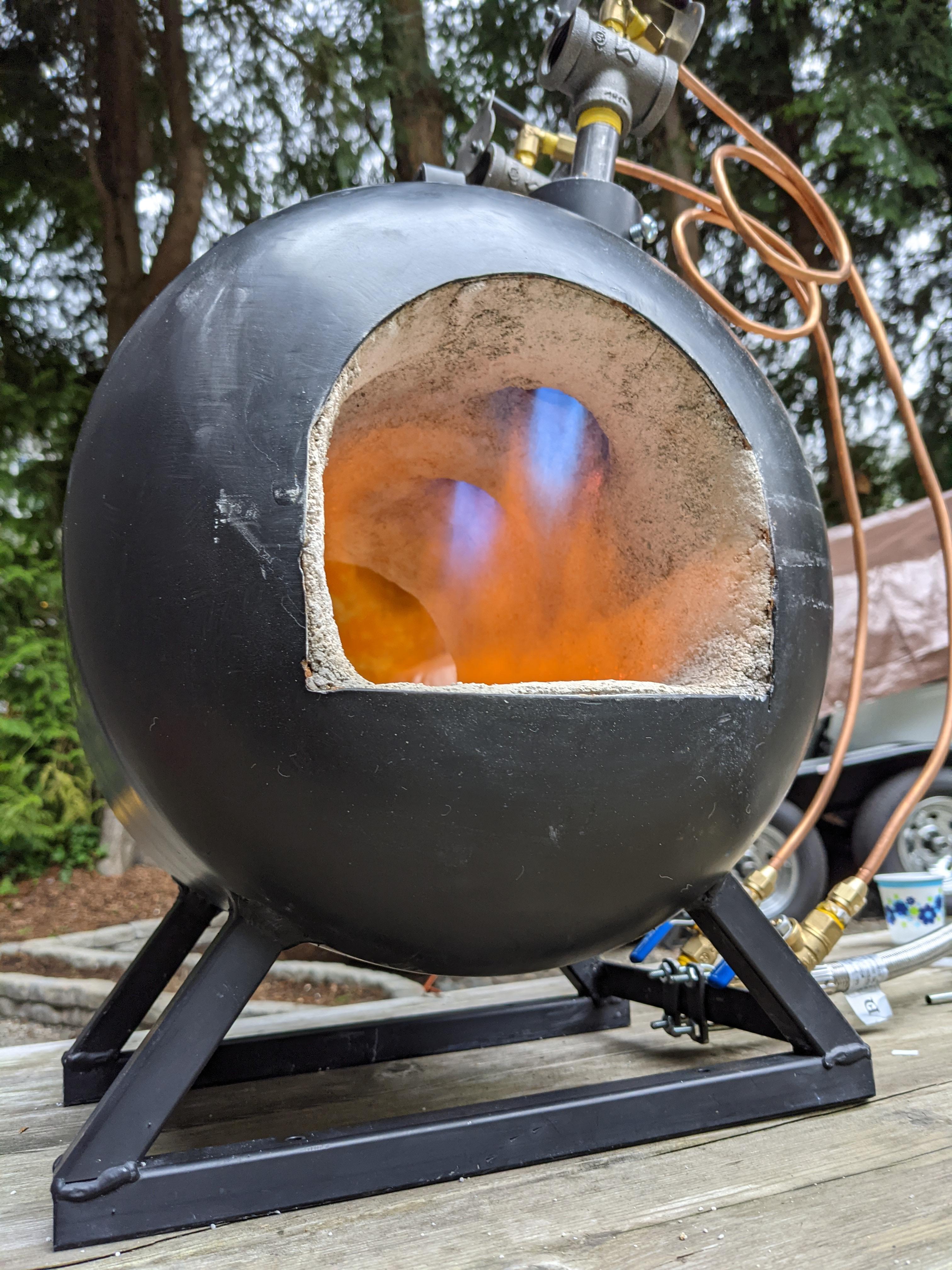
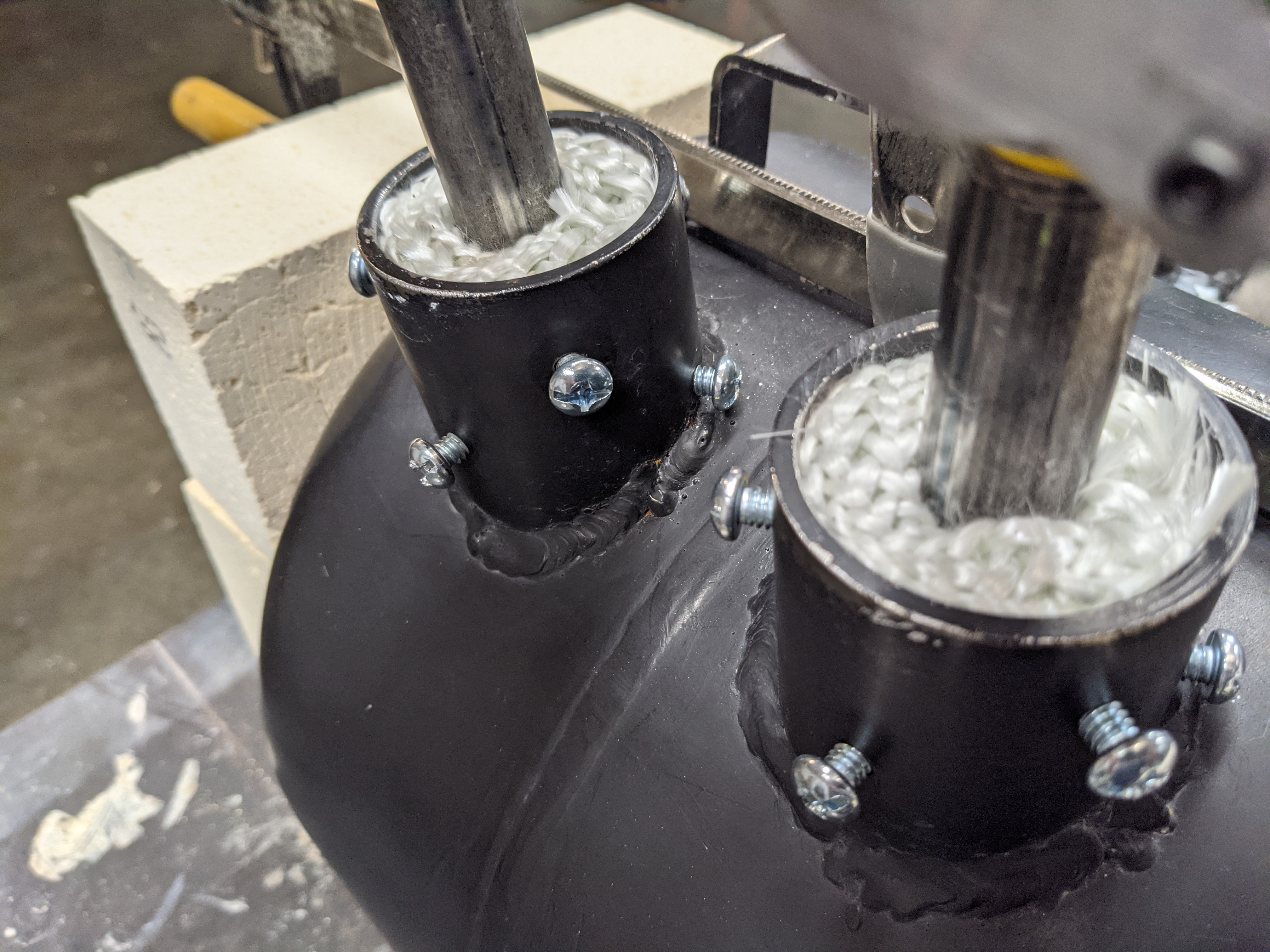
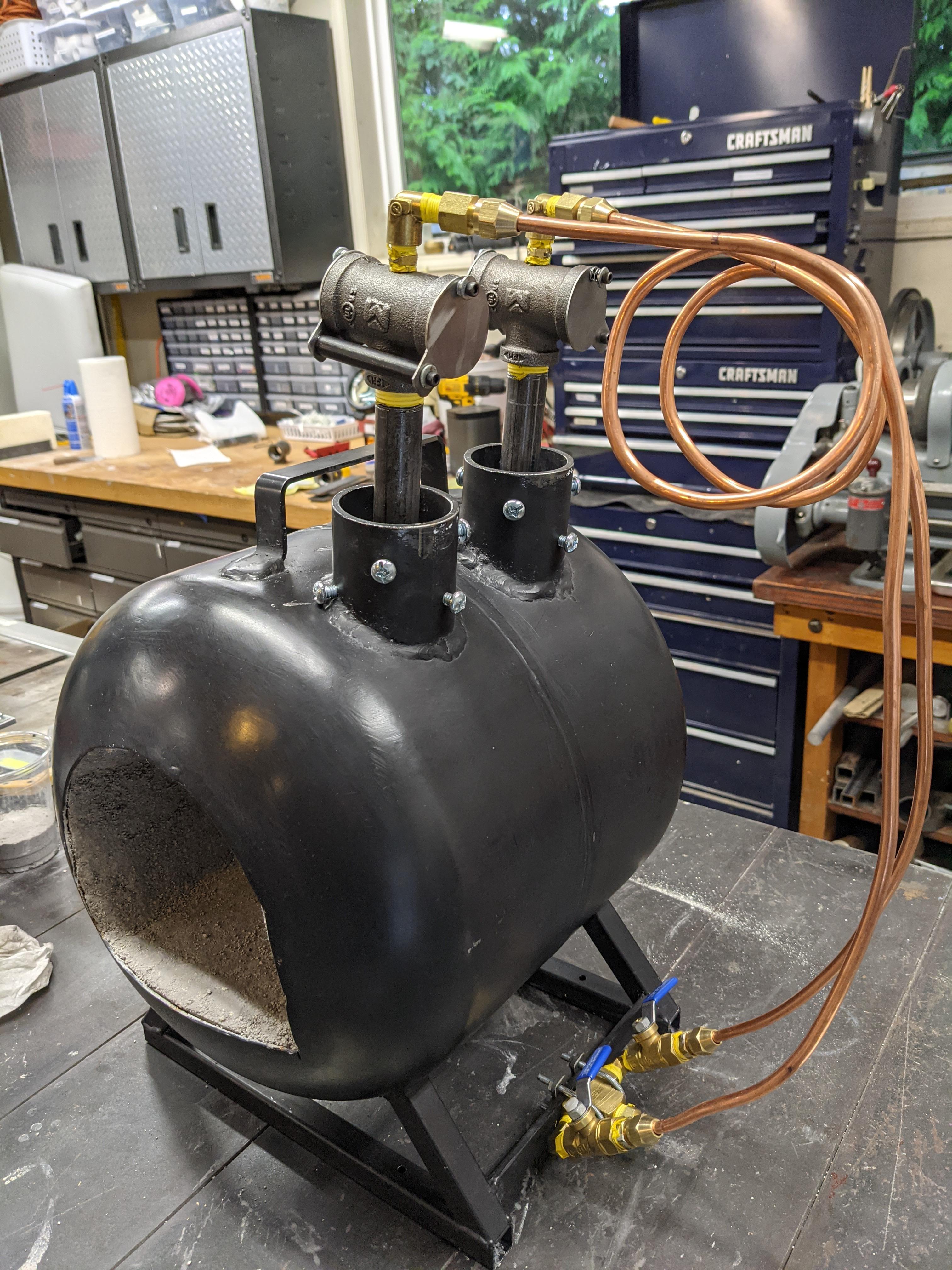
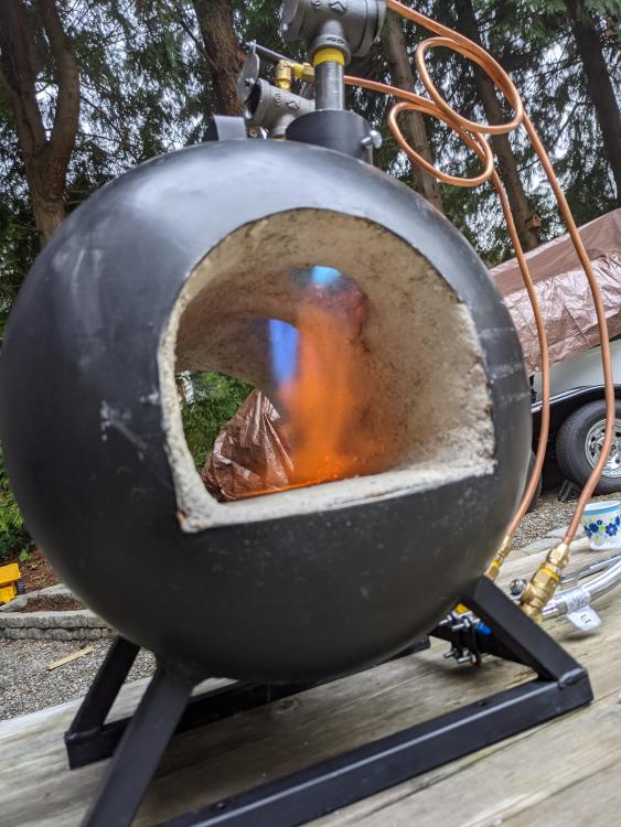
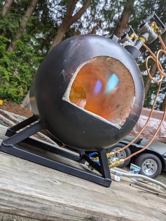
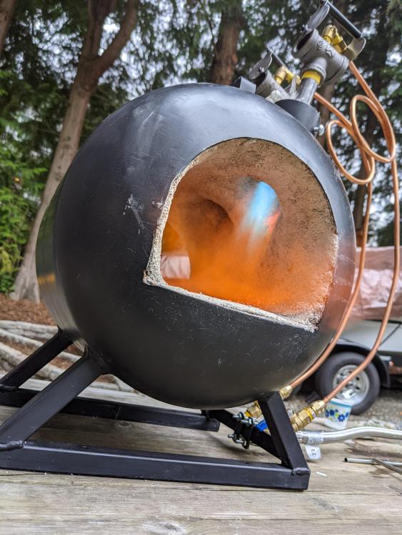
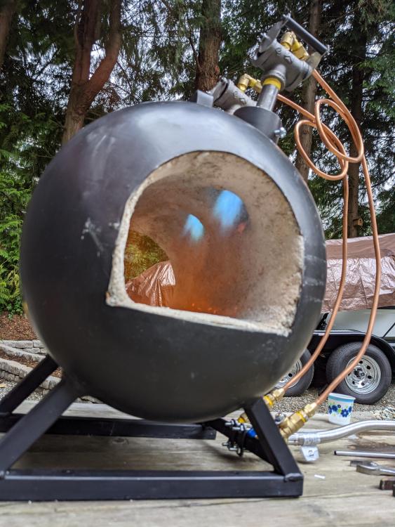
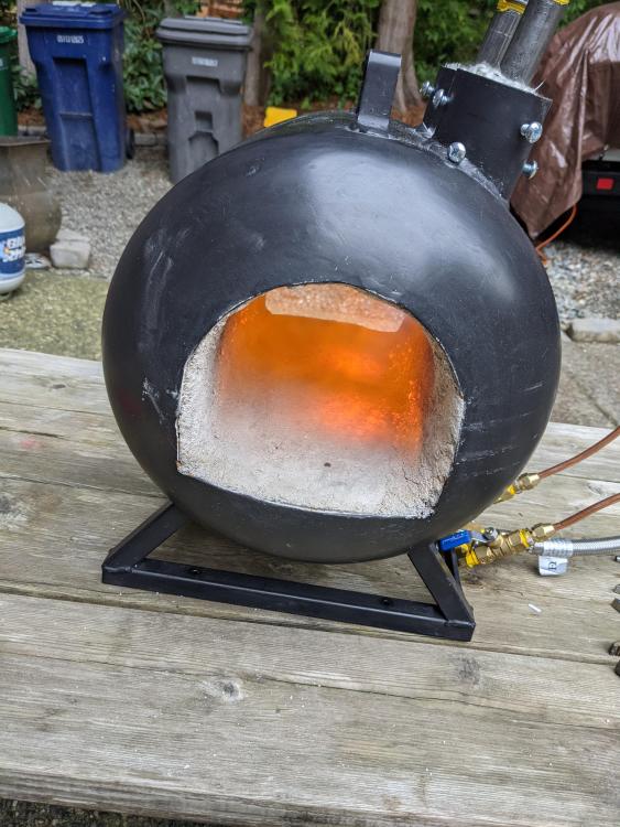
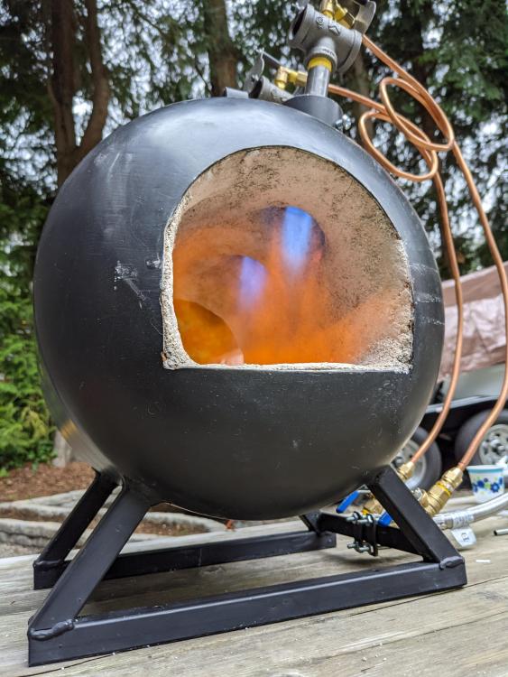
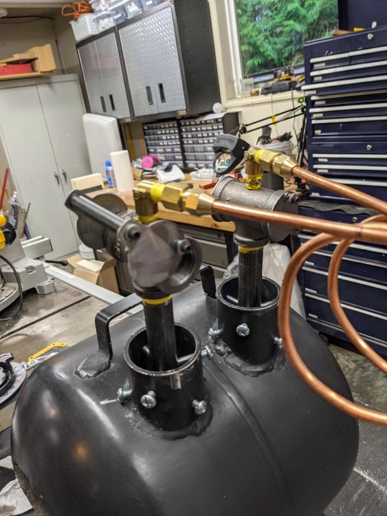
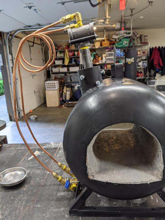
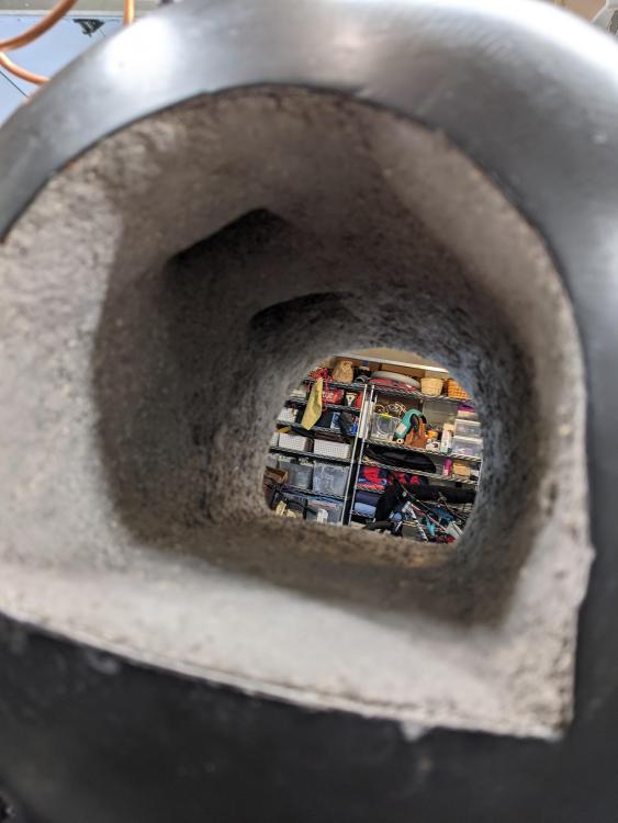
I did a test fire of my forge this morning. My questions/progress around that are covered in the following: Lots of thanks to Mikey98118 for getting me through all of that. Thought I'd share what happened this morning both to get ideas on what's next and to serve as a resource for other people building/tuning similar gear. I have a pair of 1/2" Frosty T-burners in my forge. Call them the 'near' burner and 'far' burner in the pictures. I decided to start with .025 MIG tips cut down to 1/2 size, as I have a box of them laying around. They protrude about 5/8" into the Tee. I set my propane regulator to 5 psi. On initial fire the far burner seemed to do fine with the chokes all the way open. I could barely get the near burner to fire and opening the choke all the way invariably caused it to blow out. I also noticed that the color on the far flame was blue while the near seemed to be teal/green with lots of orange splash on the floor. I swapped out the .025 tip for a 1/2 length .035 tip on the near burner to see what would happen. I got much more fire/heat but still a green flame. This did not feel like progress. At this point I decided to let it cool off so as not to overdo it on the first fire. Looking around at old posts it seems like a green flame indicates a fuel rich burn. My first step in troubleshooting was to swap the 1/2 length .025 nozzles between the two burners. I was trying to isolate this as either a nozzle issue or a problem with one of my burners. I got lucky here I guess, as now the far burner was green/teal and the near burner was blue. I pulled both out and chased them out with a torch tip file (back to front) and that magically fixed the problem. Here's 1/2-length .025 tips with the chokes fully open. Both flames seem to be the same color to me. I believe these are the 'neutral' flame I'm looking for but please correct me if I am wrong. Here is he same configuration with the chokes about 1/2 way closed, which made the flame turn teal/green. I believe this indicates a richer mixture and was a good validation that taking time to put chokes on there was time well spent, as it gives me another knob to adjust in addition to the regulator pressure. This one shows where the flames impinge the floor. I might have a bit of fine tuning to do with the aiming of the burners but that should be pretty simple with the ports I made. I'm pretty happy with how it looks so far after the initial troubleshooting. I couldn't get the burners to stay lit in a vise outside the forge so was pleased that they both could hold a flame the first try. Troubleshooting was just a case of RTFM (in this case previous posts) to see what I needed to think about. On my to-do list is a set of big washers on top of the burner ports to control air flow through there (they're stuffed with fireplace door rope at the moment) and an application of kiln wash once I've got it fired a few times and all the moisture driven off. Please let me know what else might make a difference here and/or what else would be good to think about. Thanks in advance for your help.

-
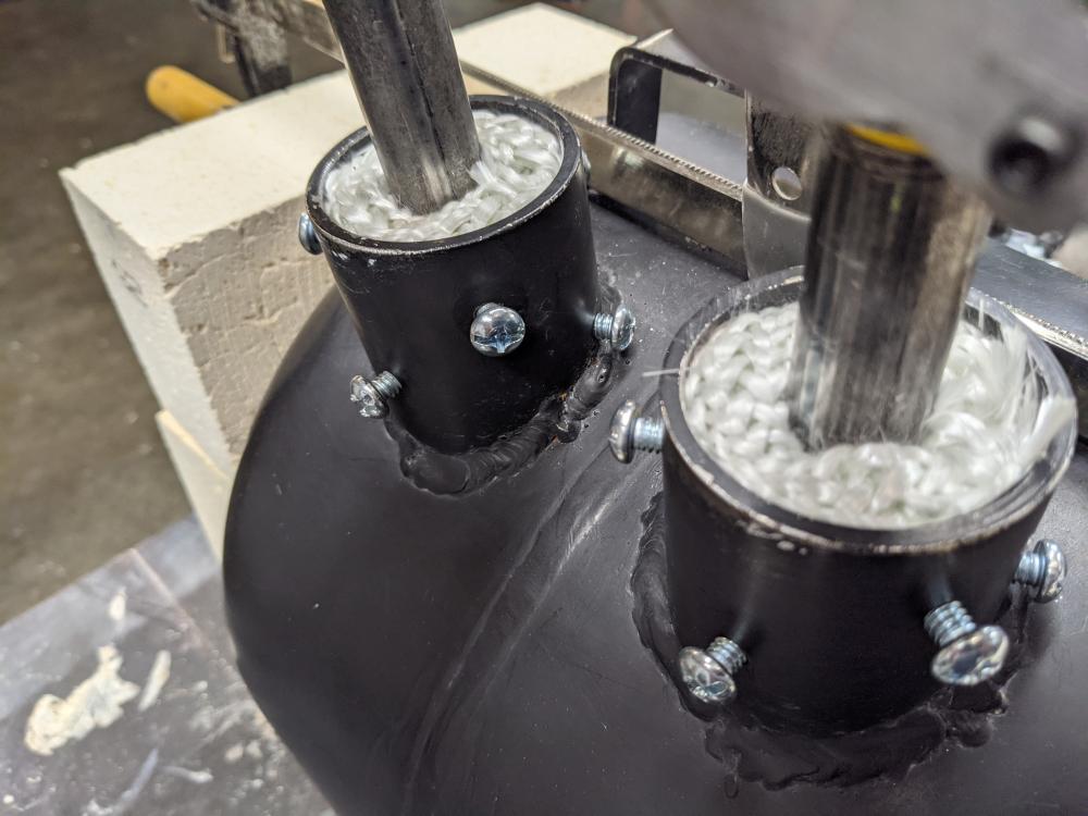
I've been thinking about that potential issue and thank you for the suggestion on big washers. I'll see what I can come up with next time I get some shop time and will post back some pics. I was initially concerned that my burner ports were too large but now that it is all put together I'm glad to have gone with 2" ID pipe. They seem just right. I was thinking I'd also use some left over ceramic wool dipped in rigidizer stuffed into the ports once I get them aimed. The McClendons near me sells the rope seal for wood stove doors, which I thought might work well on top of the wool to keep it from getting unruly. I bought a foot of the 3/4" variety to try out and it seems to be doing a good job lowering heat loss with the 75W light bulb. Obviously a different ball game with burning propane. A final mechanical layer (i.e. oversized novelty washer) should create a good stacked solution. Thank you again for the continued guidance and patience. pan widgetspan widget
-
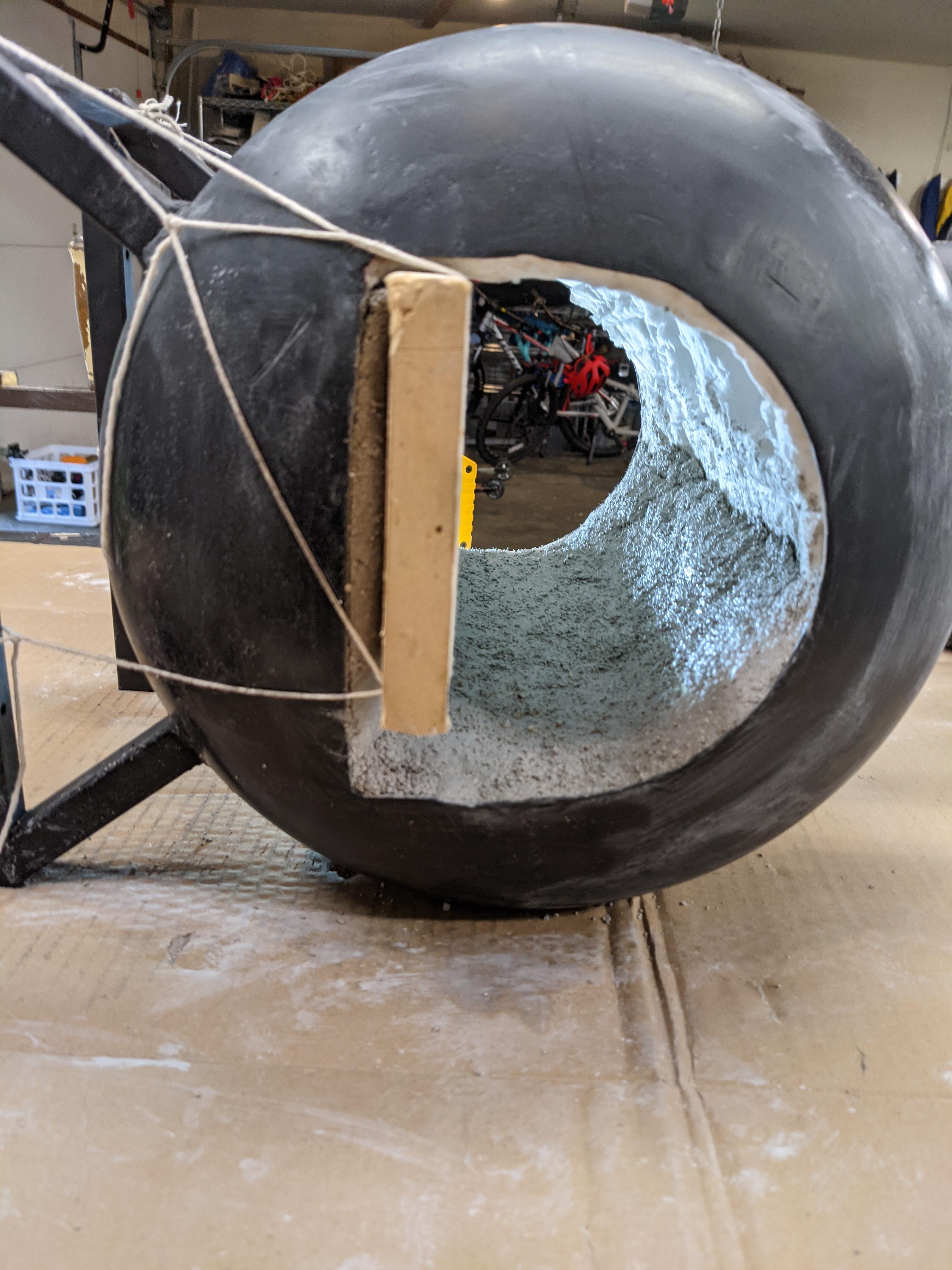
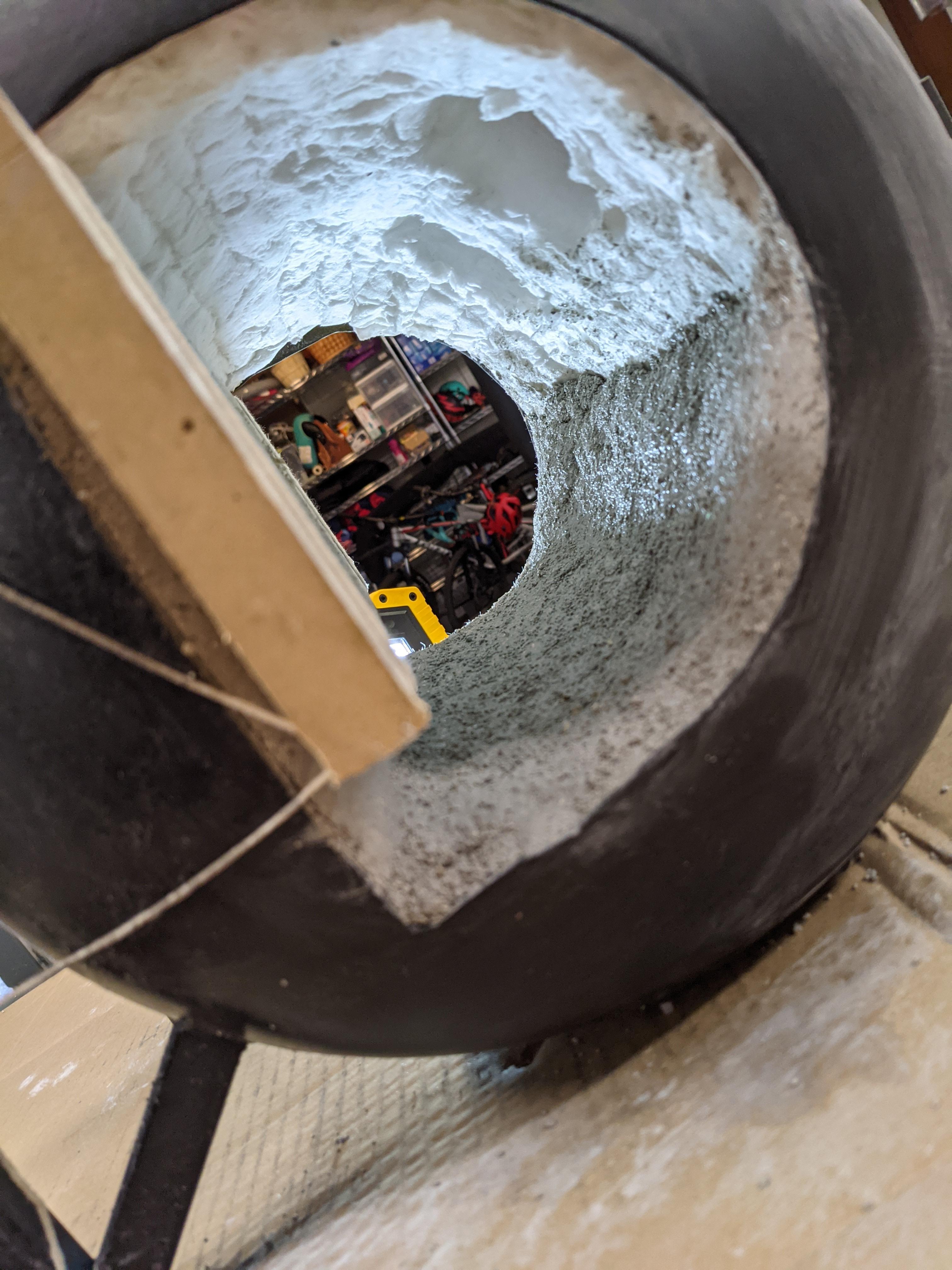
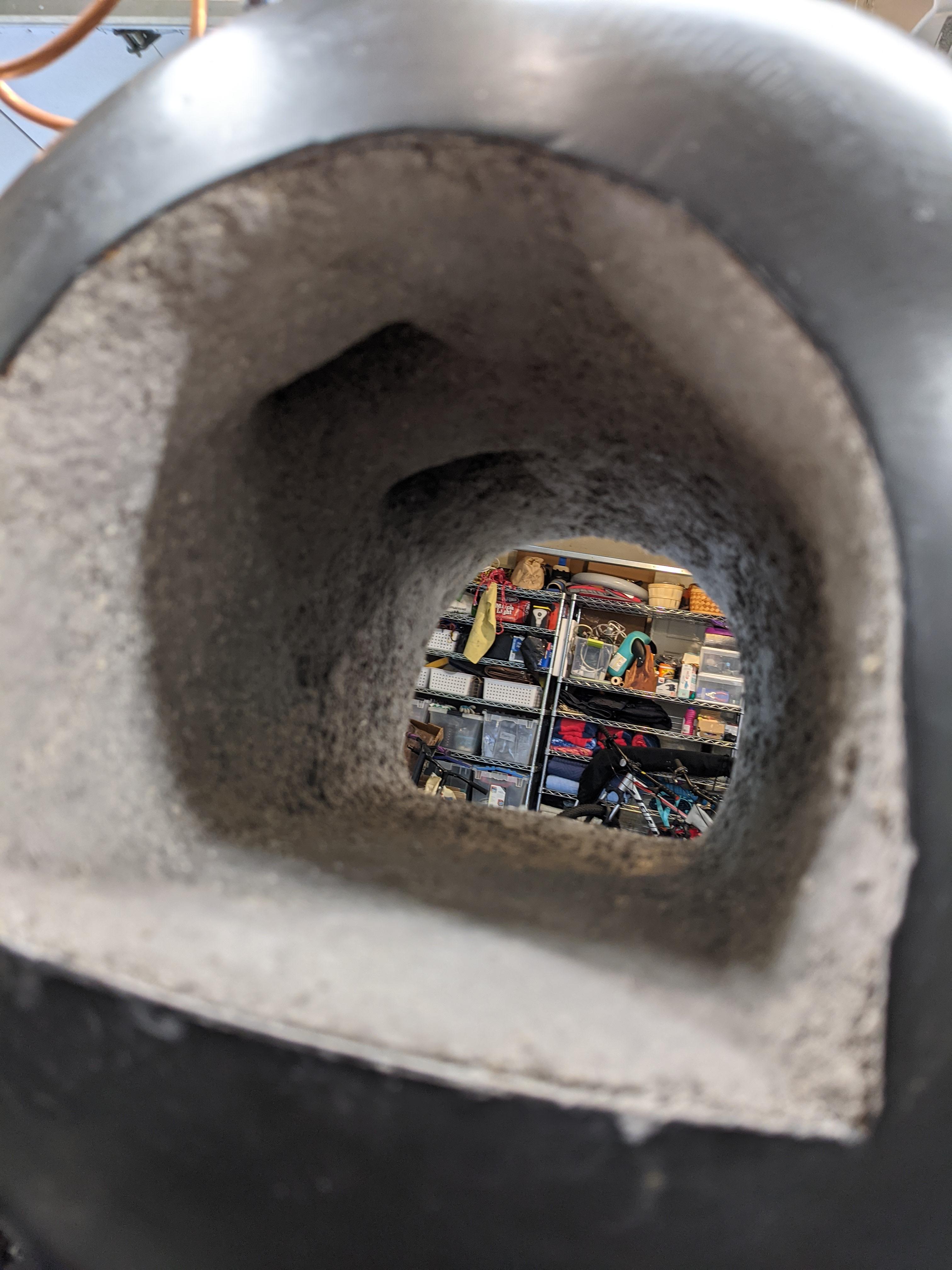
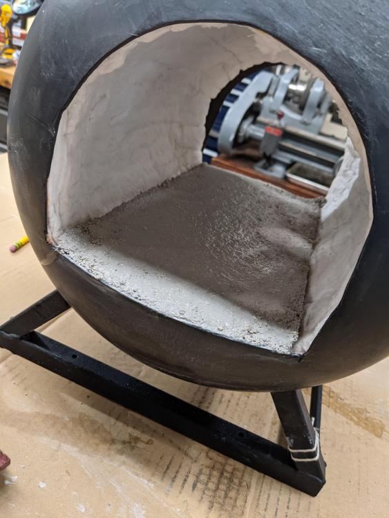
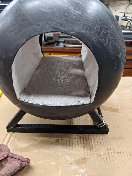
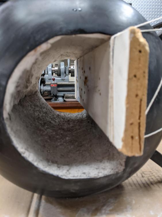
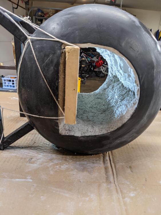
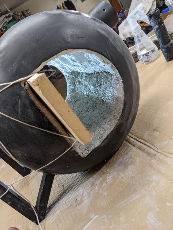
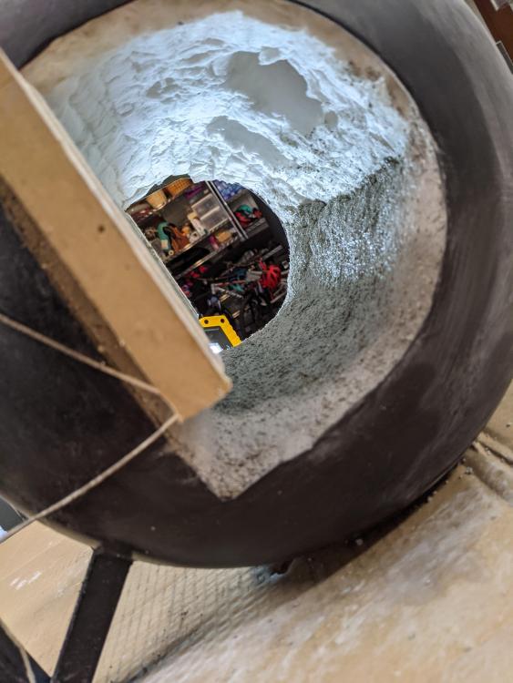
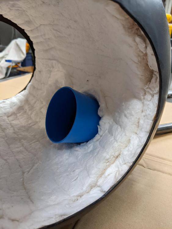
Thought I'd follow up with a few pics of how my setup finished up. Got a few pics of the liner going in also. Left it in a bag with wet towels for 2 days. I have had a lightbulb in it all week drying out the Kast-o-Lite 30 and am planning to fire it up this Saturday.


-
I think you are right. I calculated it as 1/2 of a 6.5" cylinder (the top of the arc to the midpoint across the horizontal) plus a 2.75" x 6.5" box below that but along the entire 13.5" of cylinder (neglecting the curvature of the front and back). I forgot to account for 2.25" insulation/refractory materials at each of the front and back, which makes the length about 9" (again, disregarding curvature). This gives me about 150 for the 1/2 cylinder + 160 for the box, 310 total. With the vagaries of the liner stack, it seems like 350 in^3 is a good design number. I'm going to roll with the 2 x 1/2" burners with equal parts confidence and naivety. Thank you again.
-
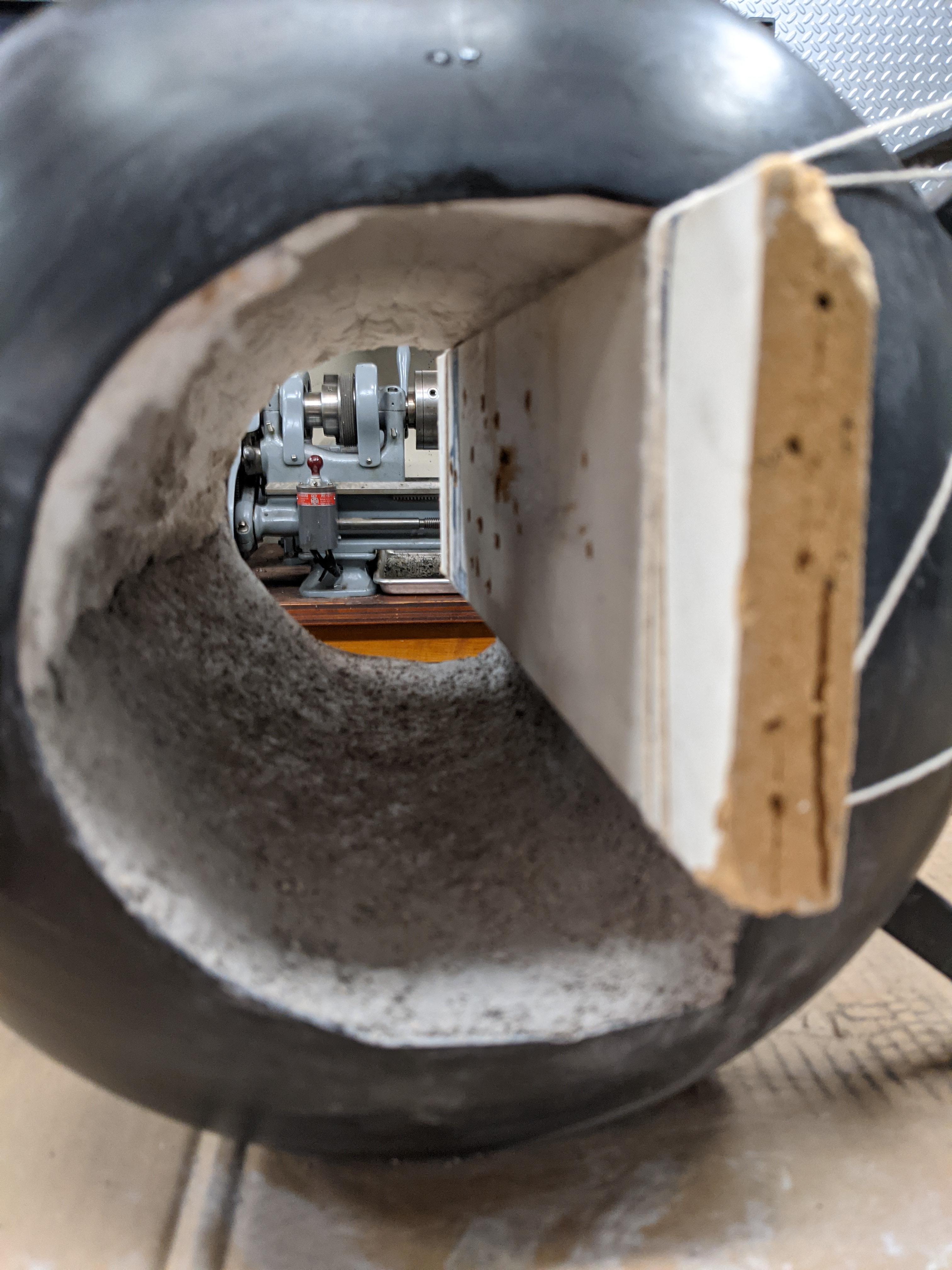
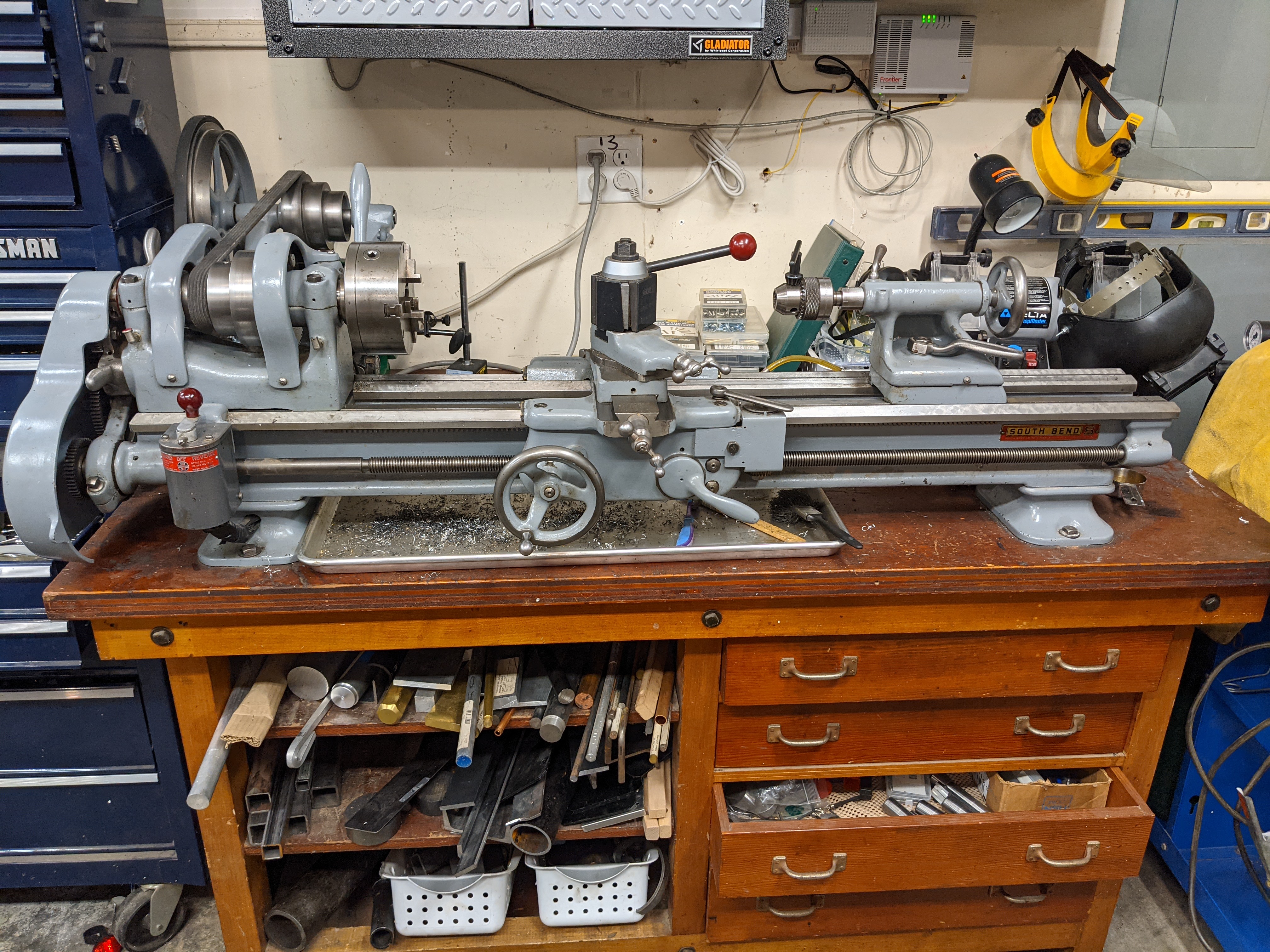
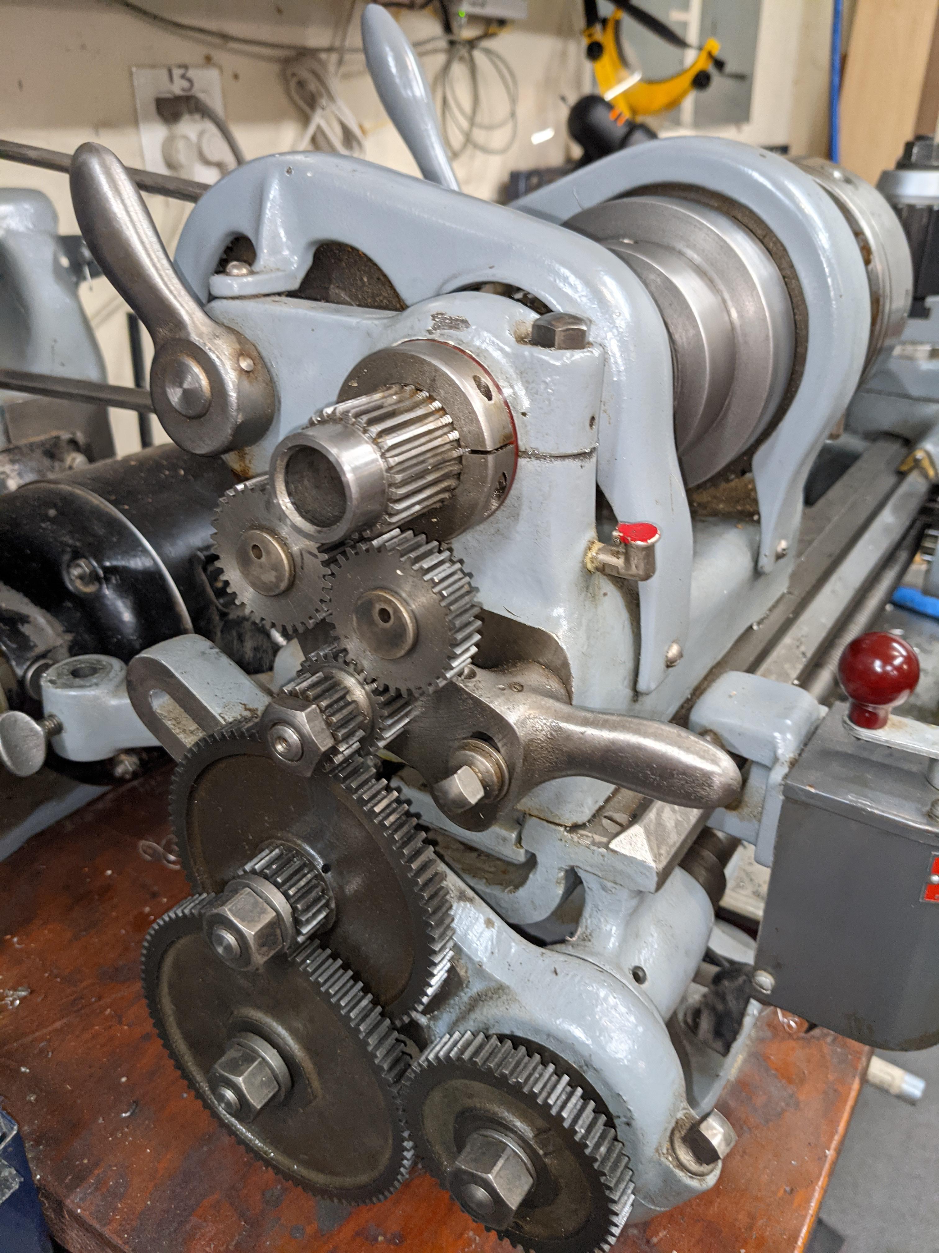
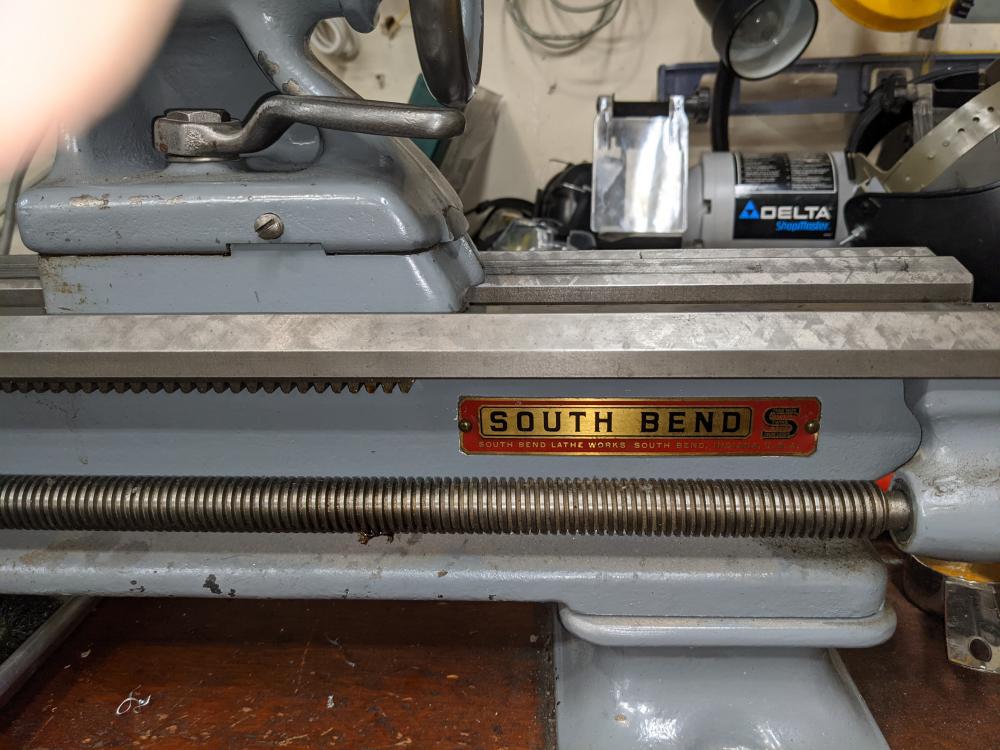
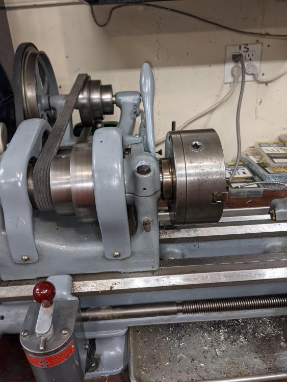
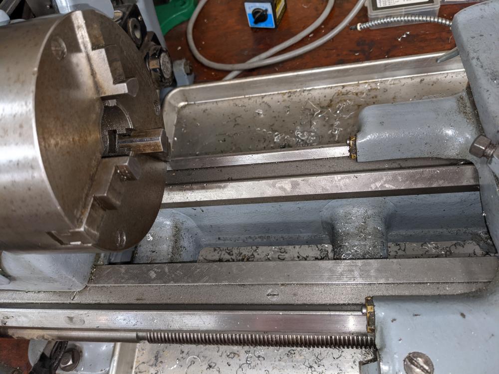
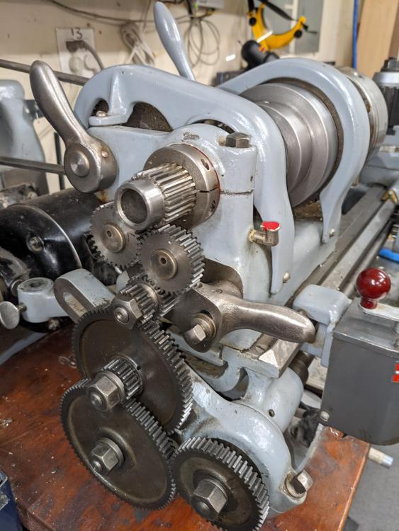
Here's my South Bend model 615-A. Purchased new at a hardware store in Seattle March 1939. This is a "C" model with manual change gears and no power crossfeed. I bought this lathe from the son of the original owner about 10 years ago and did a full restoration, which I documented It came with a bunch of cool memorabilia including original hand written receipt, build tags from the factory, and old tool catalogs. Also came with a ton of tooling including an Albrecht 1/2 keyless chuck, 3 and 4 jaw chucks, wood turning rests, a steady rest, and a milling attachment. I added the quick change tool post, as the lantern was a pain in the neck. As it was a homeowner machine it's entire life, there is very little wear and is pleasantly accurate. Most of the original hand scraping is still on the ways. They don't make them like this anymore.

-
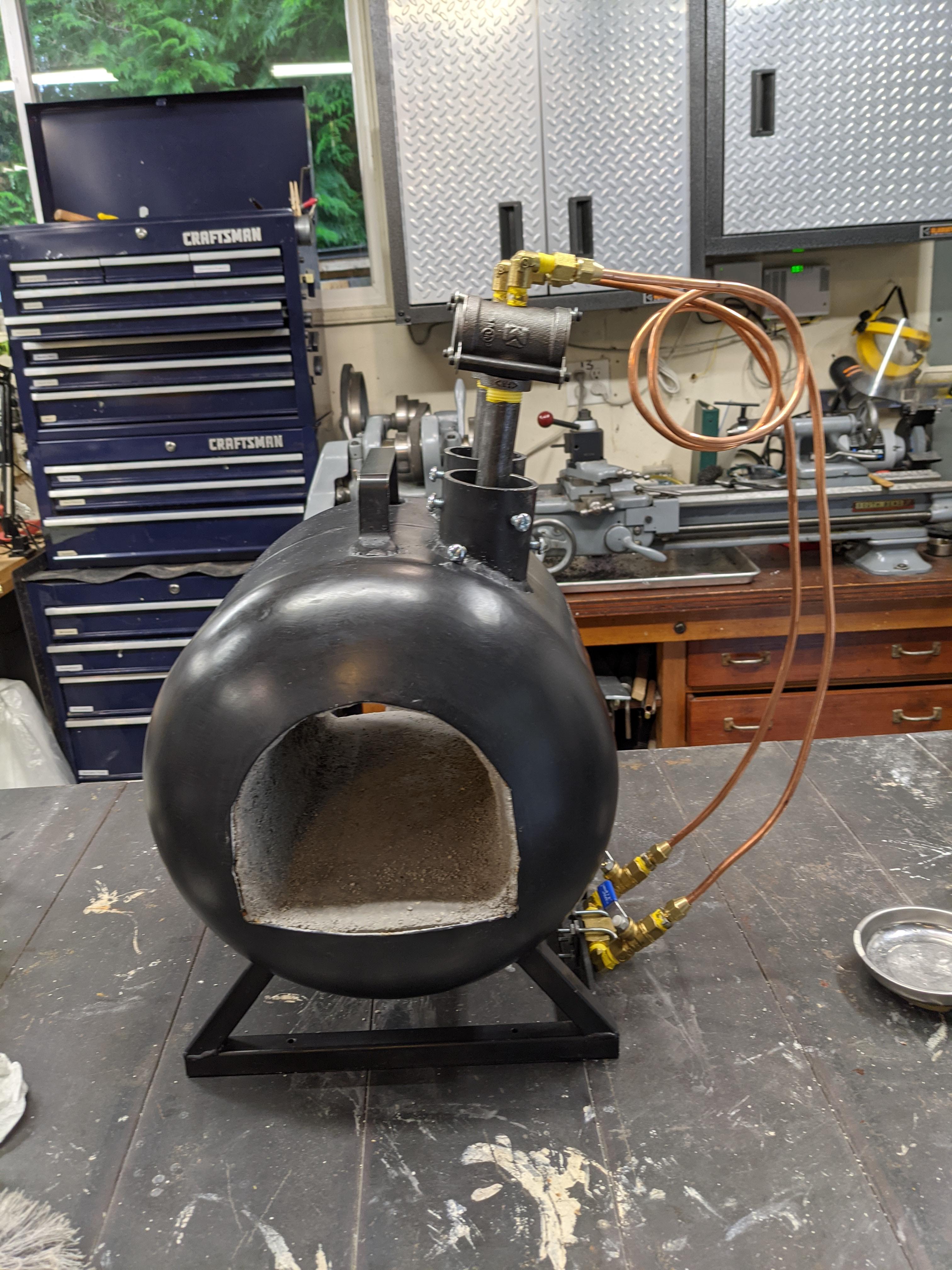
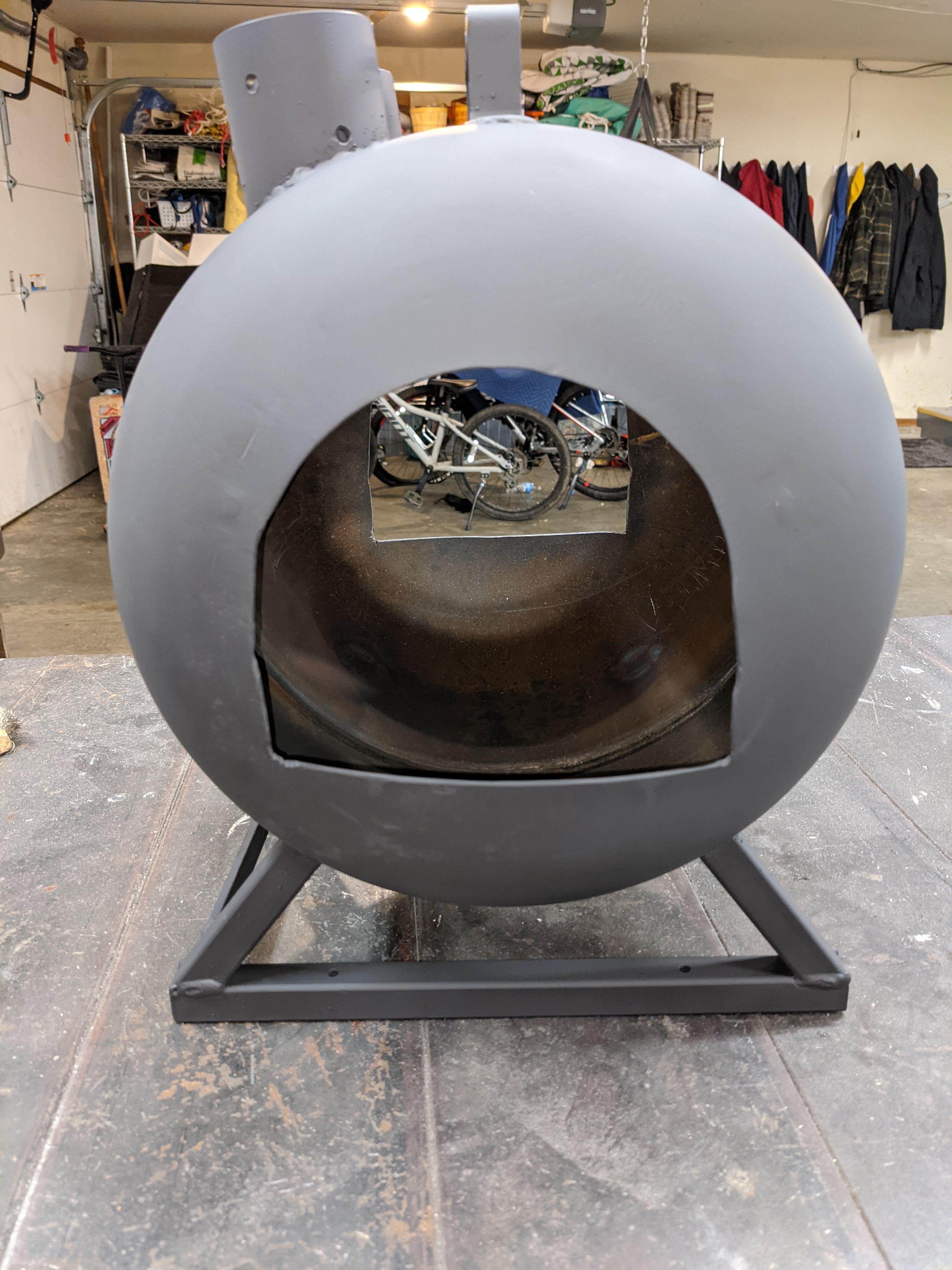
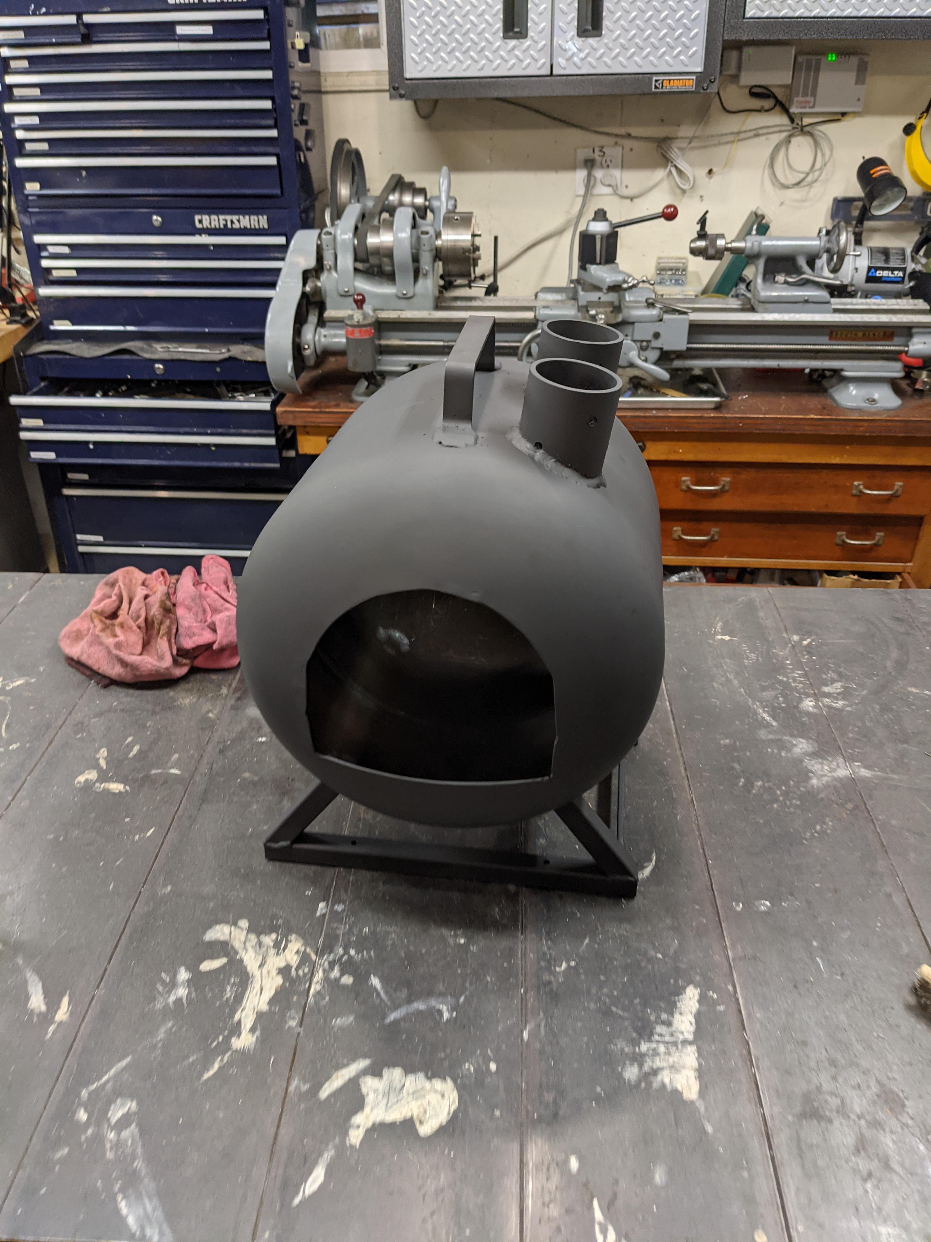
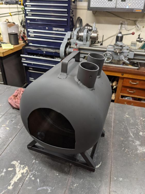
Pics of my shell with the paint on attached. Got 3 good coats out of a fresh can of Krylon BBQ paint. Thank you for the suggestion on burner size. Looks like my total volume is right at 500 in^3 so I guess 2 x 3/4" burners would be more than I need. I'll rejigger to 1/2" and read up some more. I drilled out / tapped a 1" x 3/4" tee the other day and that's when I figured out I needed to re-indicate my lathe. Turns out my tailstock had drifted out laterally by about 0.010, which I corrected this morning. Everything is running tight again. Screwing the tee onto a hex fitting I had laying around gave me a good way to grab onto it with a chuck. Definitely interested in your equipment build next summer.


-
Thank you. I really enjoy the equipment making part of hobbies, so it didn't feel like work at all putting it together. The propane tank came up on CL for $5 and Everett Steel had everything else I needed in the scrap bin so achieving good economics so far. I am planning to use 2 x 3/4" 'frosty' burners with the 1" tee at the top. Currently thinking 6" tubes on them to hit the 8-9x diameter to length suggestion . The ports are big enough to accommodate larger burners and big flares but, since my interior is about 550 in^3, it seemed like the 2 x 3/4 was about right based on what I was able to find in other threads on the site. Planning to stuff the ports with ceramic wool to keep the heat in and top it off with some fireplace door gasket. Please let me know if I'm off. Thank you again for the help and encouragement.
-
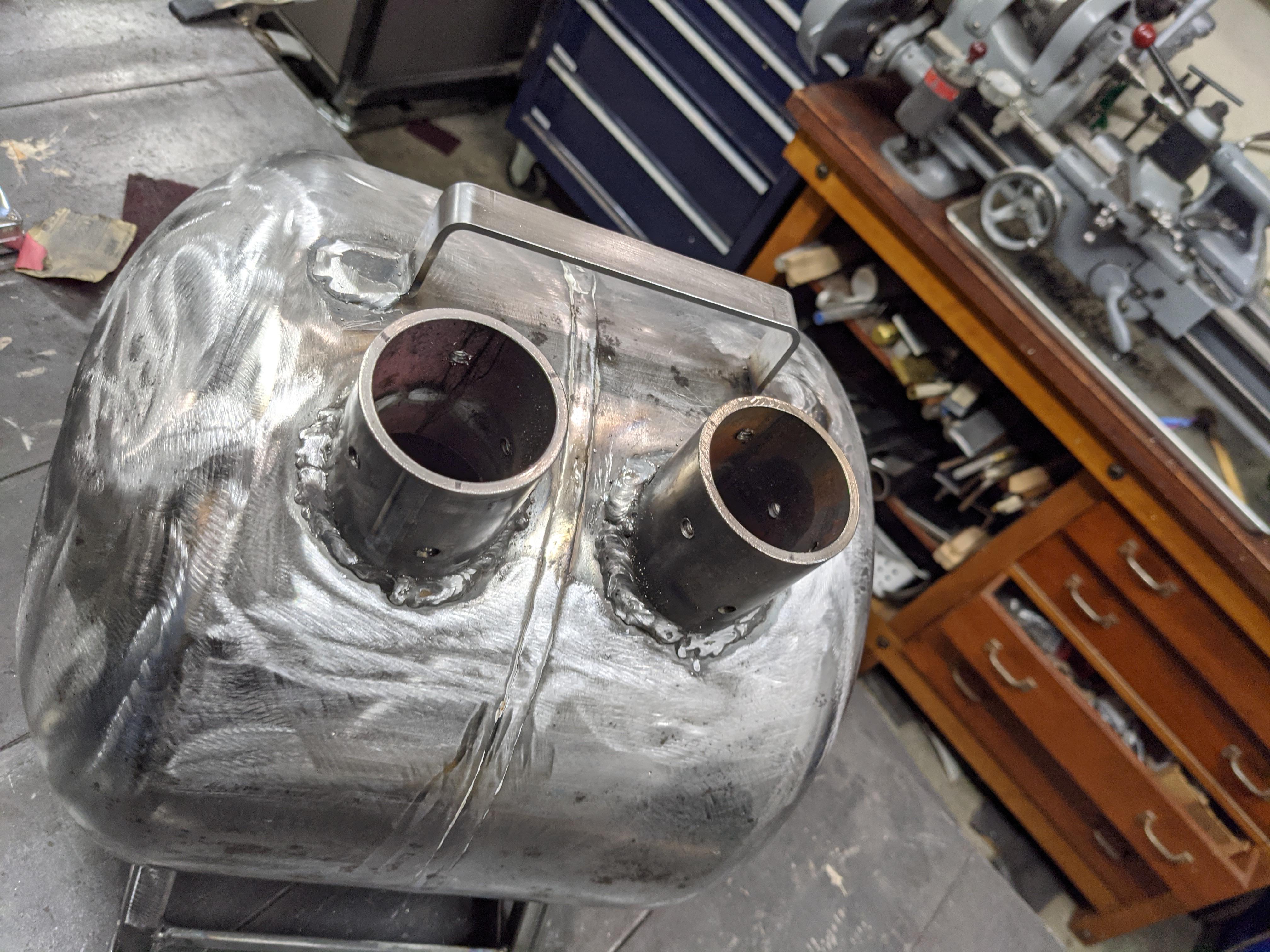
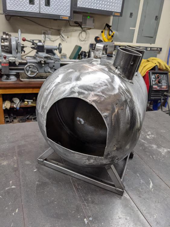
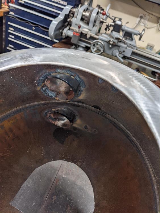
Thank you, I really appreciate the response and clarification. I moved it down 1" to 3" off of TDC and spent most of my afternoon getting it aimed to miss both the near side wall and the middle of the floor. I actually used some longer sections of 3/4" PVC pipe as "aimers", as I was concerned about not only the radial angle but also the axial orientation (i.e. I wanted to avoid pointing the burner out of the front/back of the forge). Built a temporary fixture to keep everything straight. Definitely a case of measure twice (or 8 times) and weld once. Pretty sure I'll be right at 1.25-1.5" off the near wall and little/no axial skew. My collars have two rows of offset adjusting screws which should make fine tuning possible. I'm very pleased with how everything welded up and I think I'm ready for paint now. I'll post more pictures after I get the paint on and probably more questions once I get to the insulation. Thank you again for taking time to help me. Very excited to get it in working shape. Jason

-
Thank you, glad I asked and really glad I held off drilling holes this afternoon. I decided to mess with the bearings on my lathe instead ;-) . I guess I am not understanding the clock reference, as normally I think of 12 o'clock up, 6 o'clock down, 9 o'clock to the left and 3 o'clock to the right. This is how I came up with 10 o'clock being about 1/3 of the way up from horizontal on the left. This was about 6.25" along the arc from TDC when I did the math. Apologies for not being clear on where to reference from. Perhaps easier for me to understand if I could think in terms of degrees from TDC and/or just an absolute measurement since its a propane tank. Thank you again for your patience. It's my first time building anything like this and I figured I'd ask questions to avoid making egregious mistakes. I appreciate you taking time to point me in the right direction. I hope you have a Happy New Year.
-
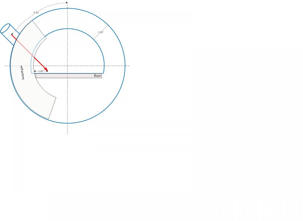
Thank you for the replies. A primary goal of missing both the near side of the wall and the work pieces in the center makes a lot of sense and clears it up for me. I was stuck on something else I read that suggested putting the burners at 10-15 degrees down from TDC. Somewhere else had a suggestion of 2" down from TDC, which is what I have marked on there now. I was having a hard time with the geometry with the ports that high on the shell and getting the flame to hit the near side of the floor at an angle that would also induce swirl (rather than splash, as Thomas noted). Updated my diagram; is this "more correct" than before? I do want to double check that 10 o'clock means about 6.25" from TDC (πd/(1/6 of a day) = π * 12/6 =~ 6.283”) for a standard 12" diameter propane cylinder. Thank you again for the help and patience.
-
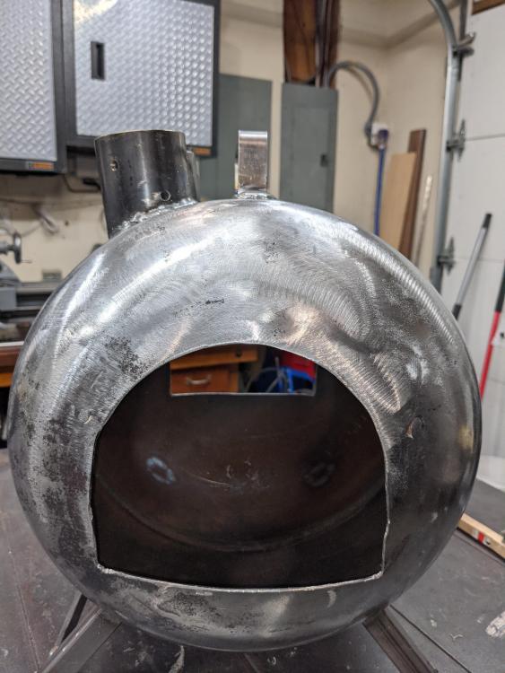
Really great board, thank you to everyone who patiently answers questions and shares their experience. Doing my first forge build out of a propane cylinder and would like to make sure I have the burner angle correctly figured out before I weld everything together. Been reading a few related topics and currently focused on the following as my guiding principles, which I found in a thread from March/April 2018: Frosty: "I think you'll have better conditions in the forge if your burners are aimed at that angle short of the center of the floor rather than the far wall." Mikey98118: "Mount the burner in position, and check to be sure the flame will impinge near tor the near end of the shelve, but clear of the wall." I tried to draw this out to make sure I have the right understanding. Is this correct? Attaching a pic of the tank with the cutouts and the legs on. The second one has a swag at the angle these ports will sit at. Heading out there this morning to start drilling/taping the burner ports. Please let me know if I'm way off. Thank you in advance for any ideas.