saxby
Members
-
Joined
-
Last visited
-
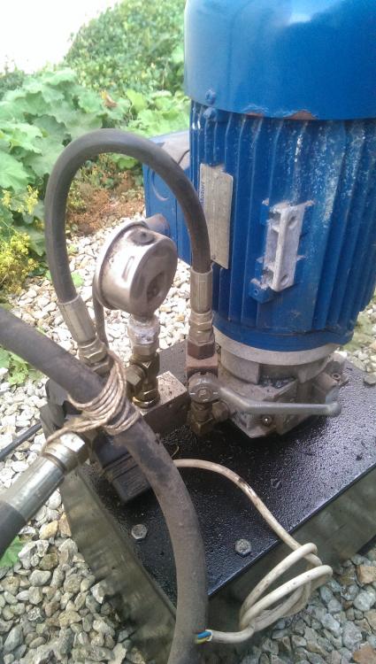
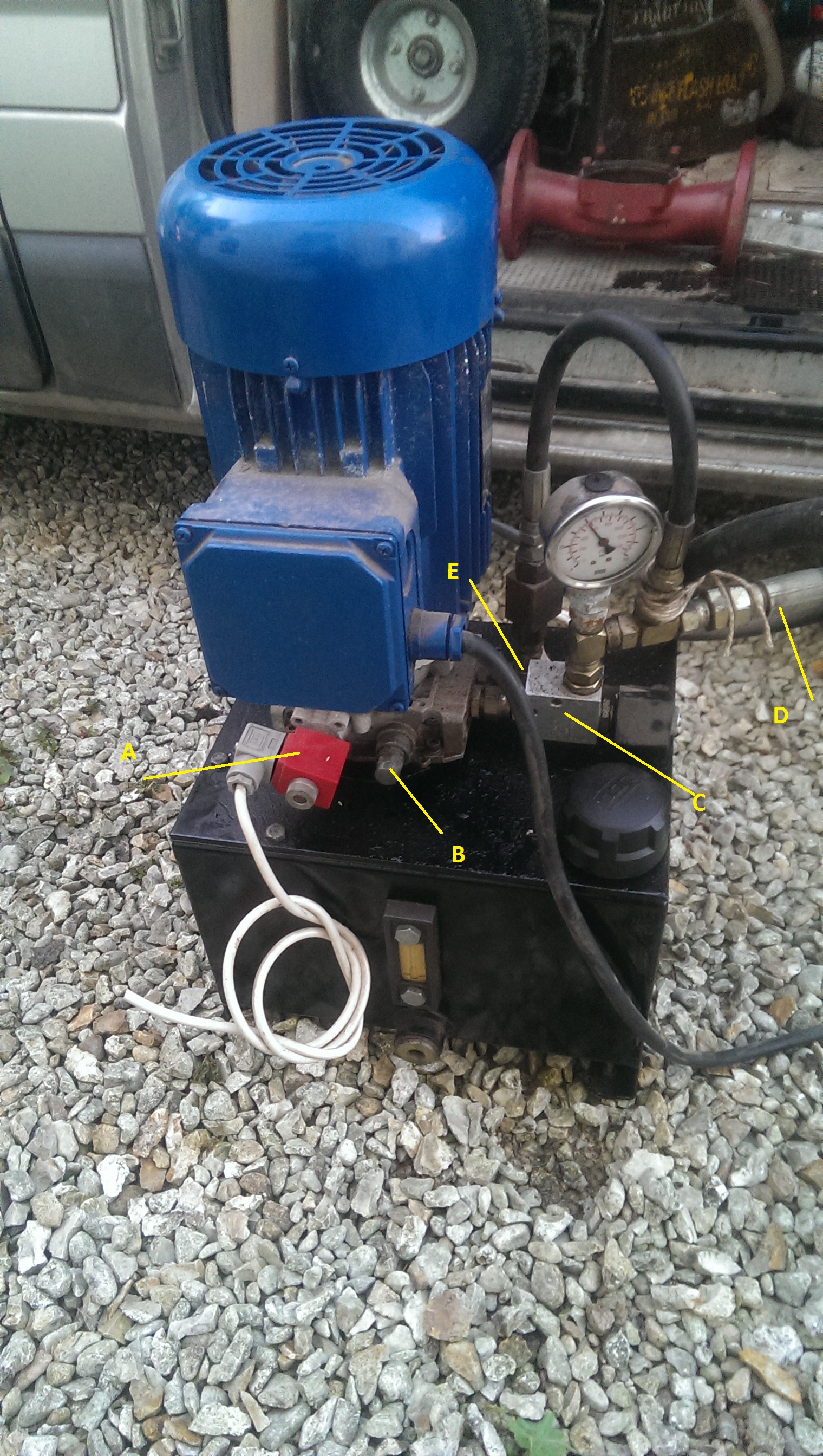
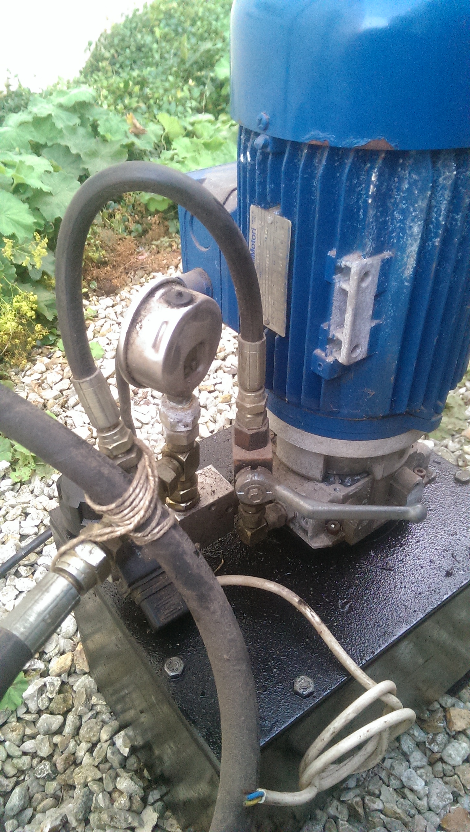
tdriack thats good advise and yes at the moment there is just one hose leaving the unit . i imagine that port E is a return on a bypass [ with the valve open i can blow down the hose, so the air has to be going some were] and i imagine that solenoid A needs to be powered on , as the pump works it seems to do nothing with out the solenoid A active [is there any need to even have a solenoid on the system . ] the iron dwarf im in hull. if the 3 merchants i went to i was told to come back next week when the expert was going to be in one seemed to think it was a large bit of kit and i could power what i wanted off of it [when i have got my self a ram i was going to build the rest of the rig and get some new hoses made up i think im planing things based on the spec i think it it . comparing it to outer simmiler set ups online as with out more parts i cant realy test it looking online eg , i dont know what flow rate t his will work at. i think it will be about 2.3 L/PM and a max pressure of 210bar [3000PSI] but i am i right in thinking if you set the pump to go for 200 bar for example it will affect the amount of flow you can get, and as you say. slow down the ram so much it starts to become useless at 1.1kw [1.5hp] giving out 2.3 L/PM. its a bout half the figures compared to your 2.2, does that mean i should be looking at a smaller ram ? say 50mm bore?
-
hello..i might be in the wrong place with these questions. but im looking to build a hydraulic press. to use when forging . there are lots of designs’ out there on the web and i think i have most of it all figured out apart from the power pack i have acquired for free it came off a large road barrier system. operated by a key card system.and im guessing that the hydraulic ram must had a spring return ram [ that and the Wight of the retractable barrier] as on the power pack i have there is only one hydraulic line going out .i have got a photo here and just a have a few questions as the people at the local merchants weren’t much help at all SO FEEL FREE TO TELL ME I HGAVE IT ALL WRONG as im just trying to logically work it out from scratchhttps://ibb.co/c6z9e5https://ibb.co/hj0hz5form the photo im assuming that that it operates this way"D" is my line out , activated by"C" a 24v solenoid"E" is a return path to the oil chamber . the valve im told was so they could keep the barrier down during events[leaving it open would create a bypass ]"B" behind the cab there is a screwdriver slot? is that for adjusting pressure ?"A" is another 24v solenoid and i have no idea what’s it does the gauge is stuck at 600spi but i imagine that’s the static amount of pressure when it’s all switched offi have re pipeed it , so instead of "C" there is just a gauge on it . the pump ran and didn’t sound any different , i don’t know if there is air in the line and needs priming somehow. or it is something to do with solenoid A needing to be open ?i intend to have a set up were the pump feeds a shuttle valve [ came off an old tractor ] that can feed a ram to open / close made with all new hoses and with some thick 15mm angle iron i have although the gauge only goes to 14000 psi i assume the adjustment on "B" will get me more ?apart from the motor there is no spec on the unit.i can find on line, a v simmiler unit for the same intended use inc motor ,has a small 1.1kw 3~ motor will run at 25000 which is more what i think need get ram with about a 4" diameter to be able to get me about 15 ton of force which is the min i will need reallyif anyone can give me some advise on this it would be great