AxL
-
Posts
30 -
Joined
-
Last visited
Content Type
Profiles
Forums
Articles
Gallery
Downloads
Events
Everything posted by AxL
-
Took a while, haven't been in the shop for a while. I have already reversed the bevel on the air intake. I can try the enlarged flame nozzle first. Could i make a new jet by turning one on a lathe? It seems quicker than the capillary tube insert.

-
I have not done the math, Mikey did. And there currently is no choke plate, it's running at wide open throttle. Yes I got rid of that, the joint is beveled and near seamless. I'll get a photo in slightly better light as soon as I can.
-
I took off 0.020", what's next?

-
I've started a thread about the brick pile forge.
-
I recently finished a 1/2" burner build (see the Linear forge burner plans thread), and I'm looking to build a simple brick pile forge for it. My goal isn't forging as such, just hardening steel. I have a few 9x4.5x1" heavy fire bricks, what would be the best way to stack them? I understand there is a certain ratio between the of volume of the forge vs the size of the burner, what size would the forge need to be for a 1/2" burner? Should it be lined with refractory cement? I assume there are many other things I haven't thought of, feel free to enlighten me.
-
I could probably chuck it back in the lathe and take off .020". It might be a couple of weeks before I can get to it though, I have a lot of work coming up. I also kinda wanna get on to building a forge. I'll see what I have time for over the next couple weeks. I have some 9x4.5x1" heavy fire bricks, could I just make a simple brick pile forge?
-
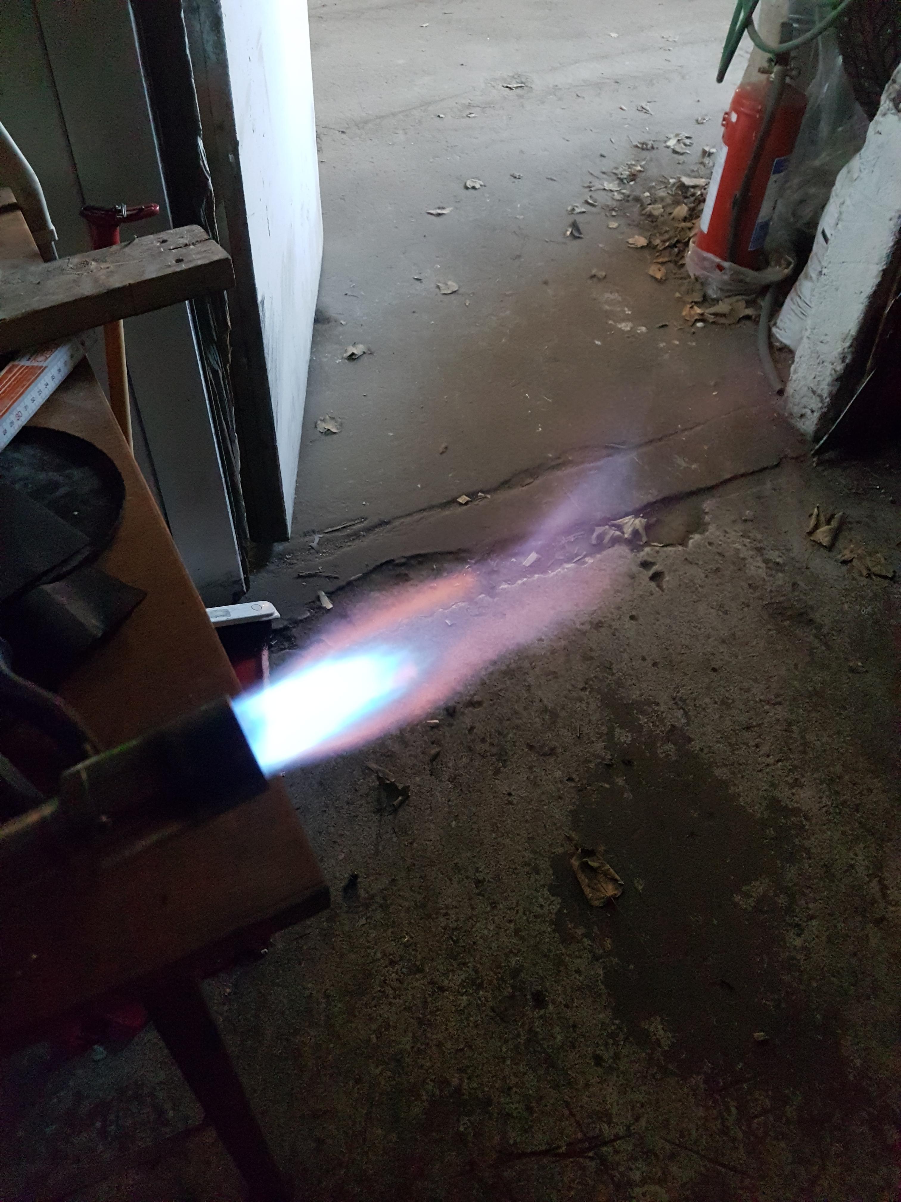
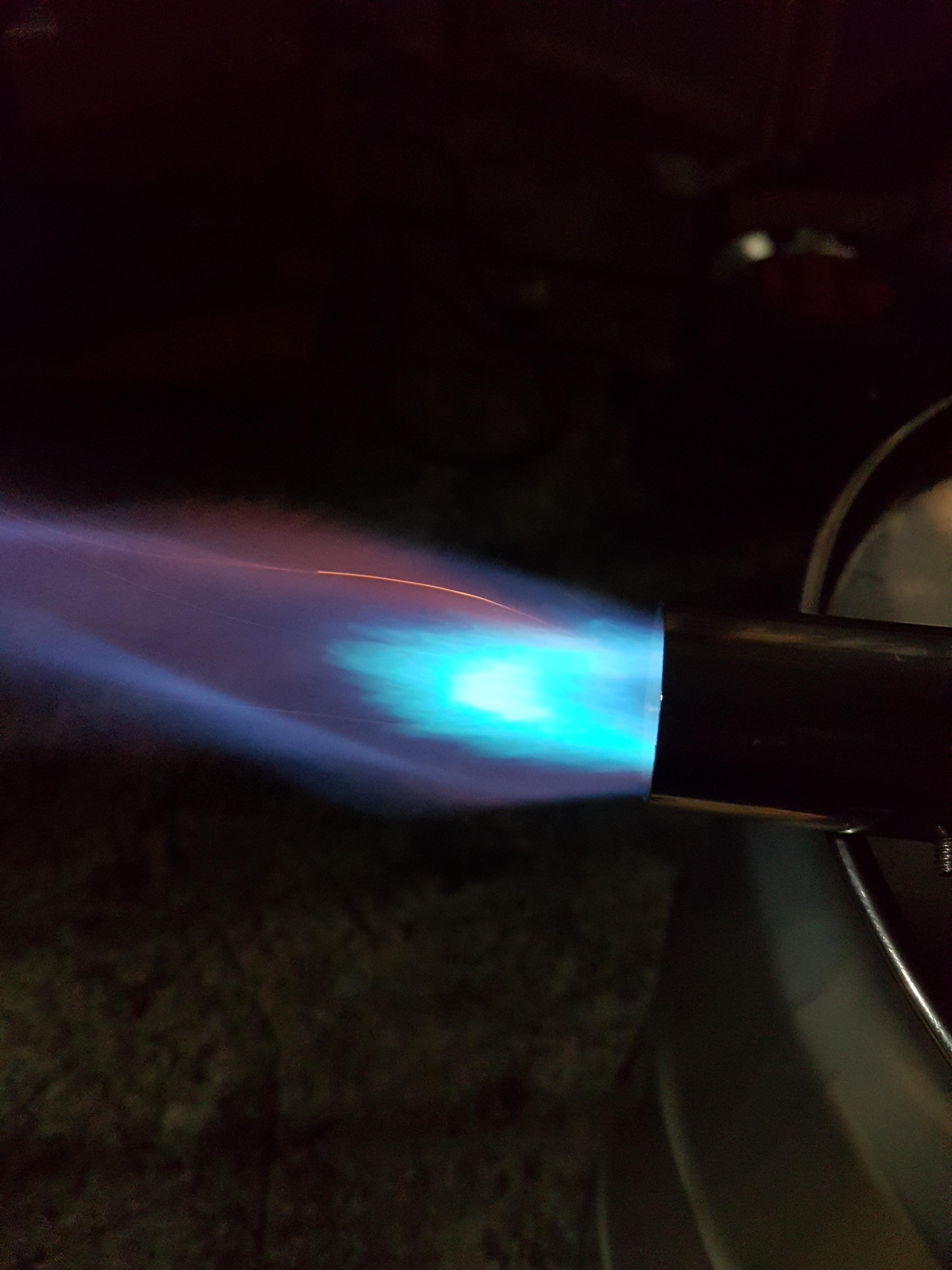
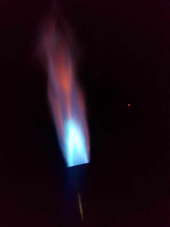
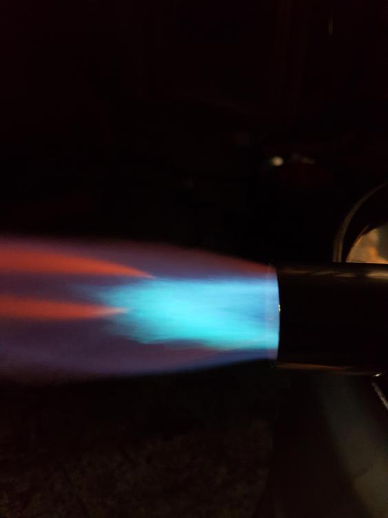
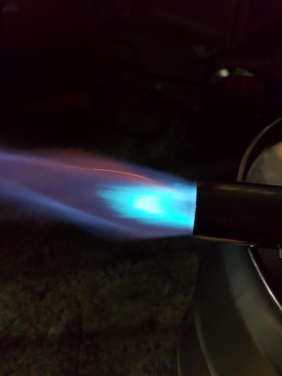
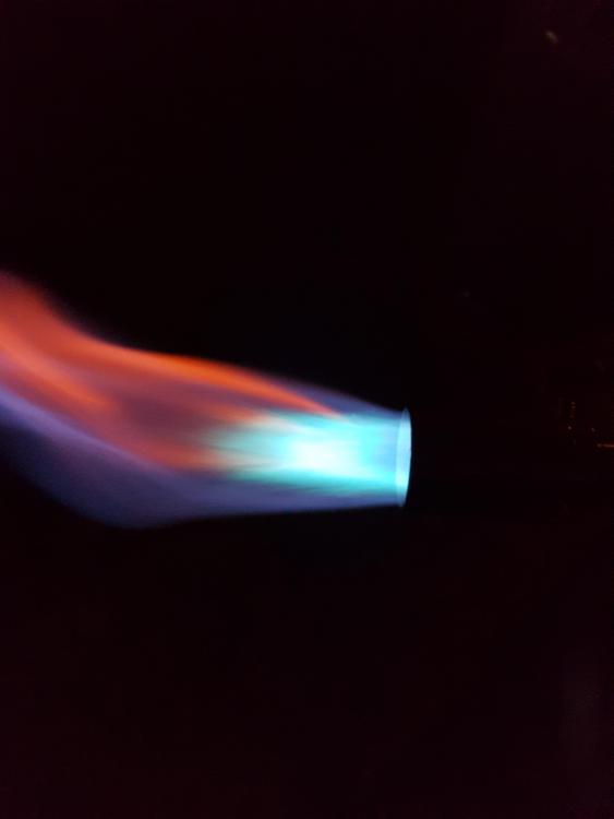
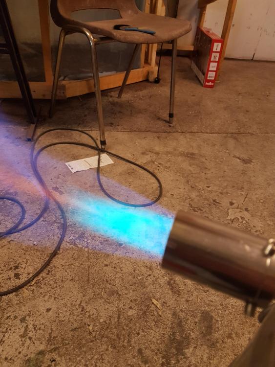
Been gone for a week, so didn't get to this before this weekend. Got the nozzle tuned, and the red flames are gone.

-
It is stainless, but maybe not 316. It might some residue from grease/WD40 or whatever was in the tube when it was used. I pulled it from the scrap bin at work. I'll give the adjusting another go later today or tomorrow. I tested it today on a small piece of steele and it had no trouble heating it to hardening temperature. This is fun!
-
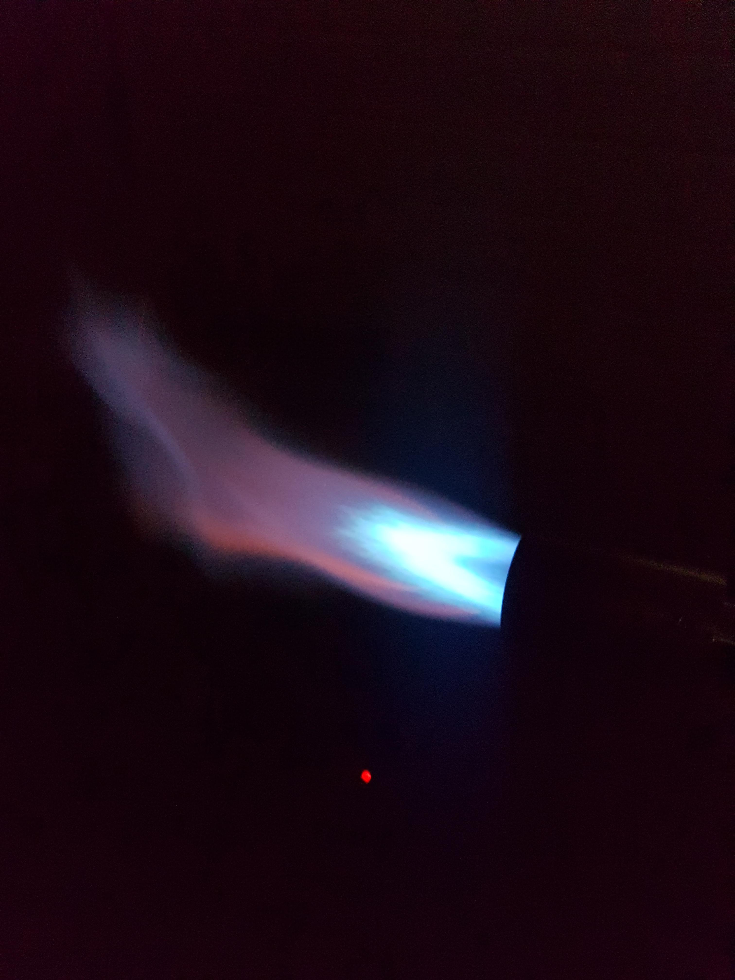
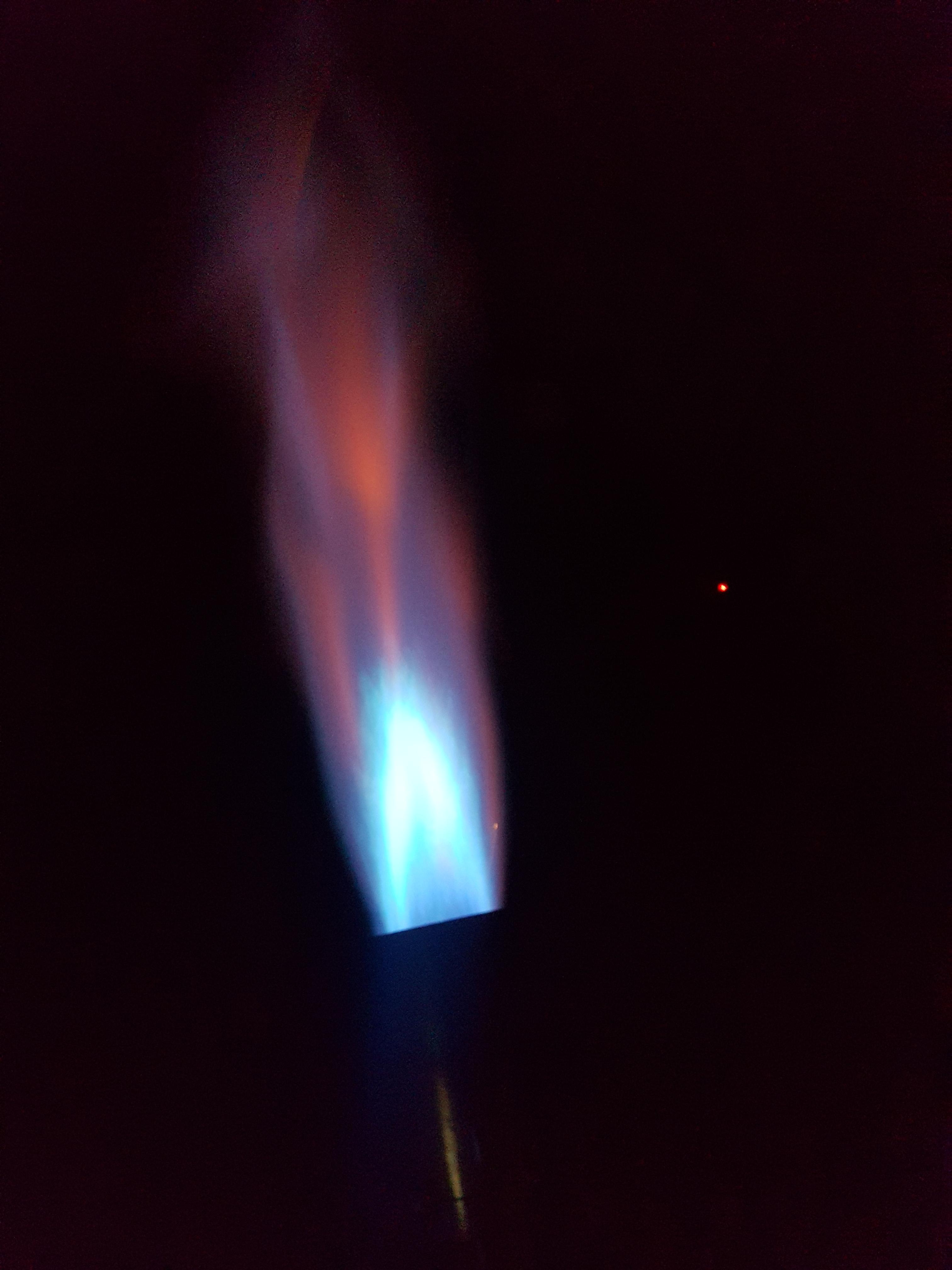
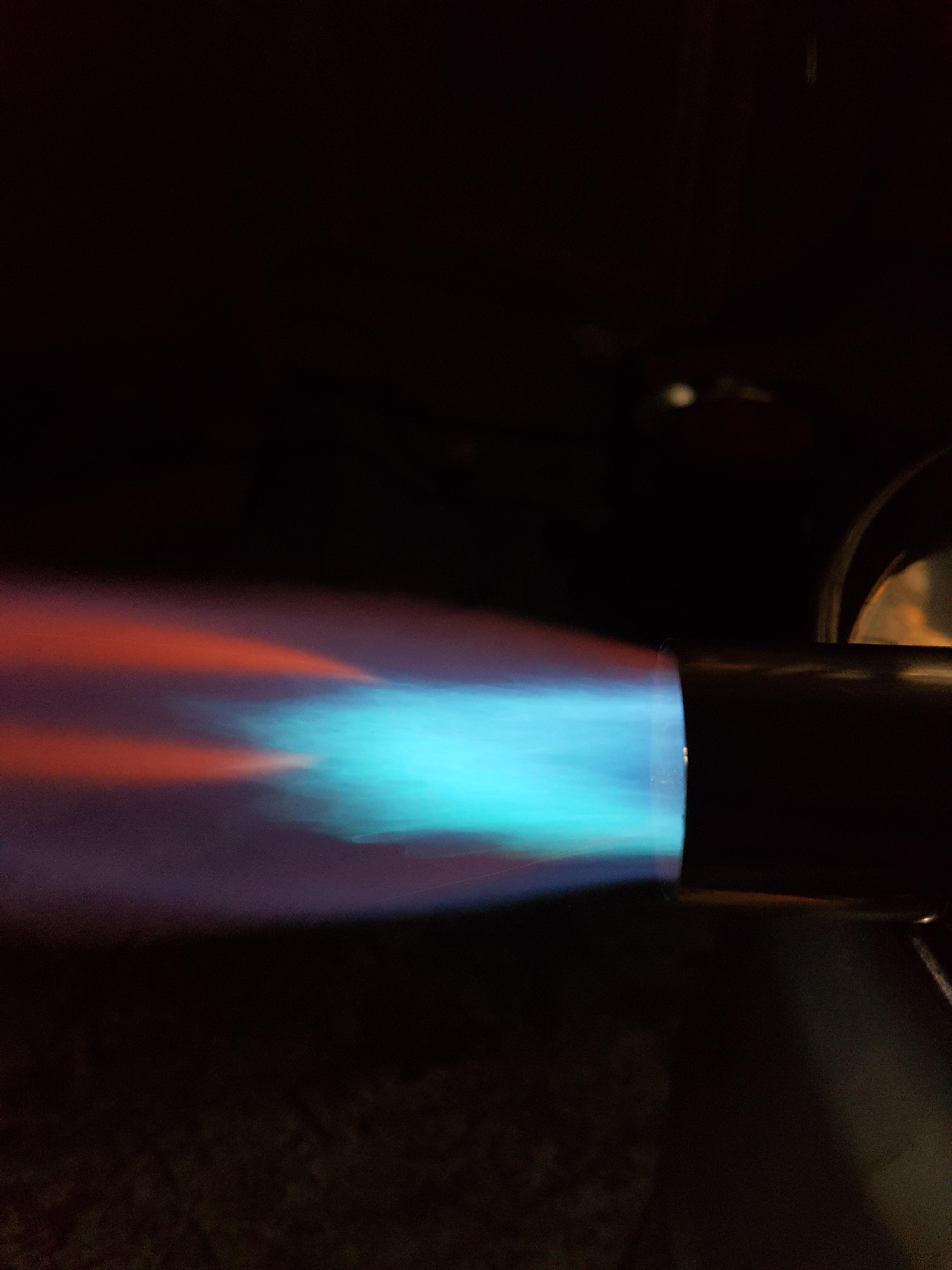
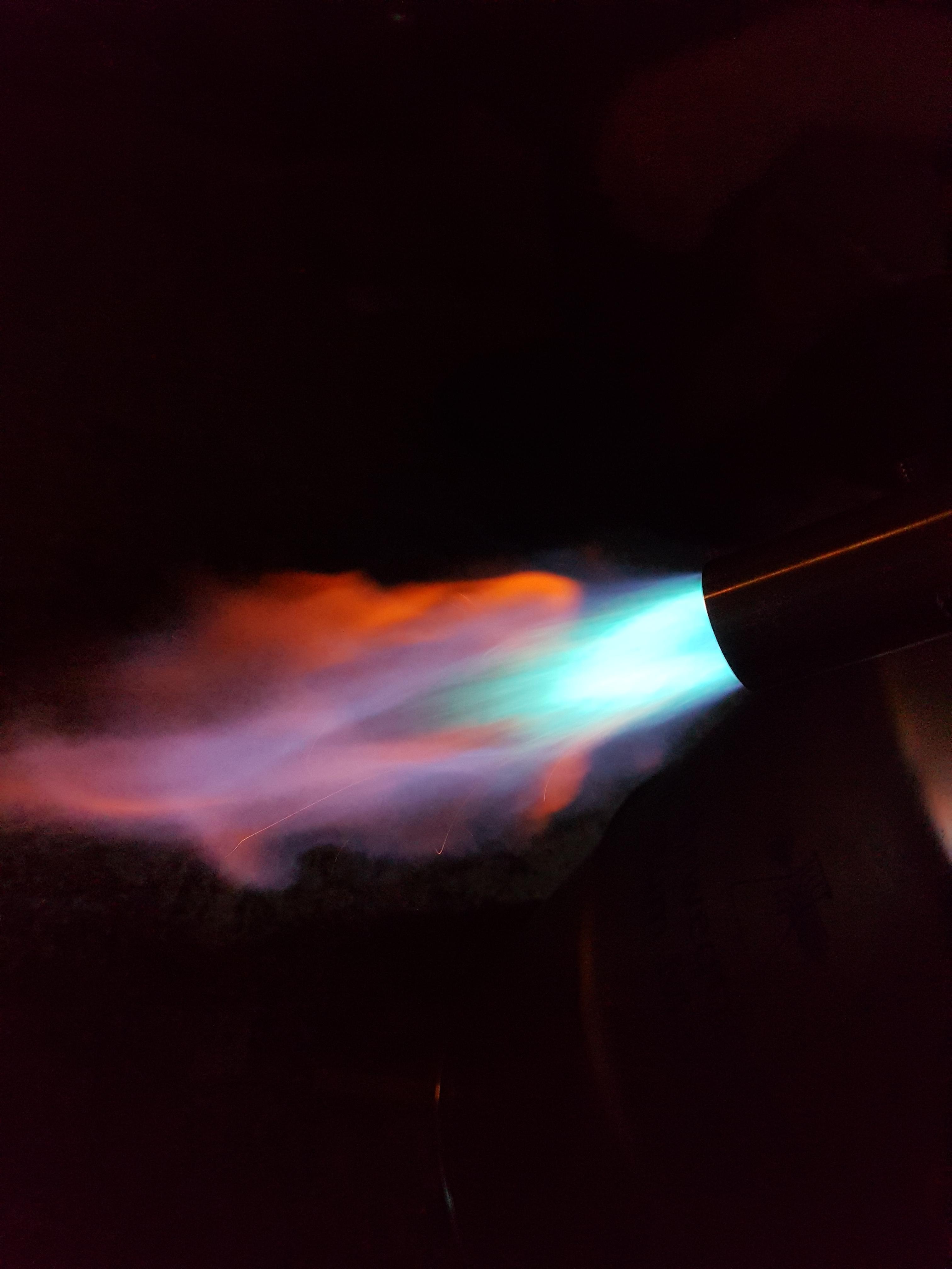
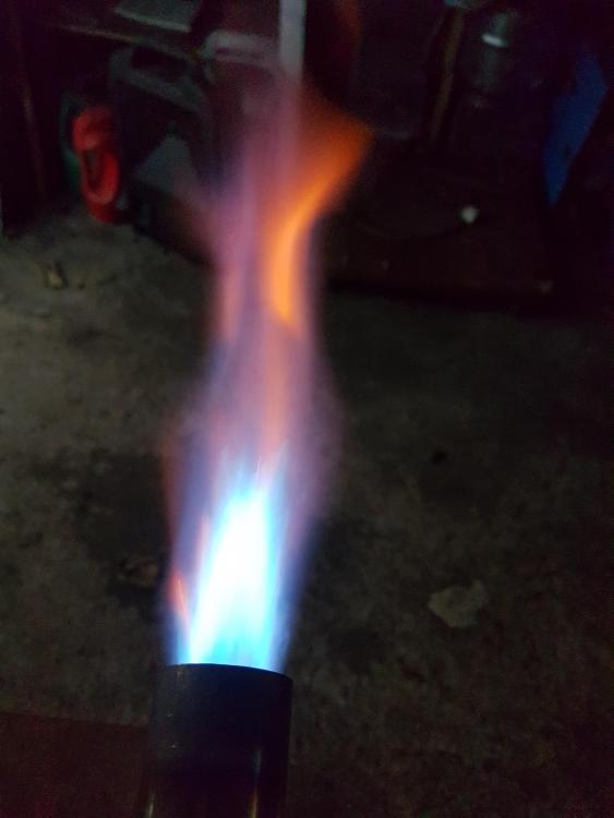
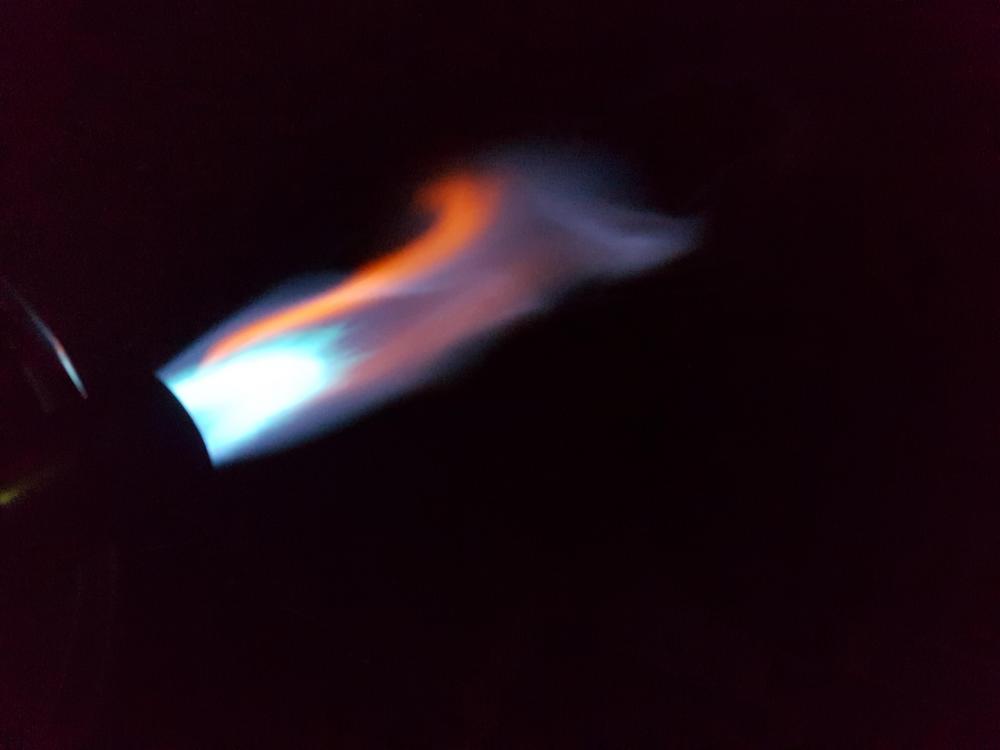
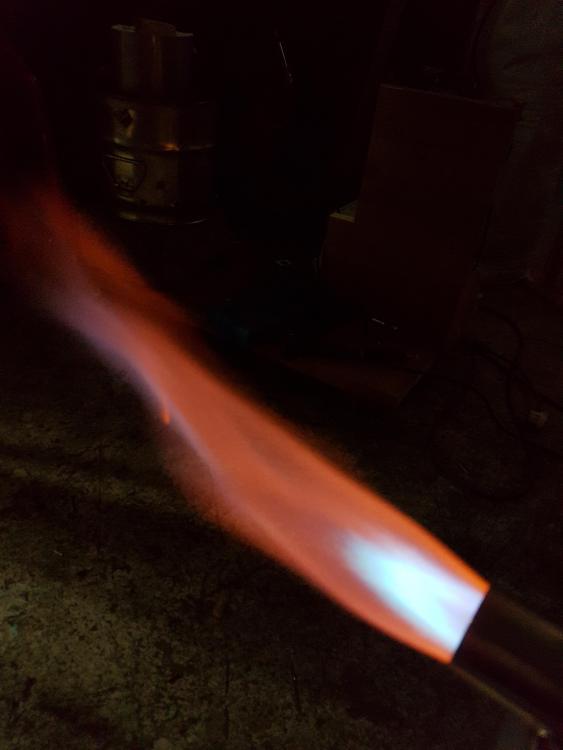
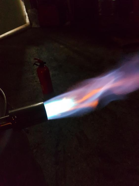
I got a 0.6 mm mig tip and tried it on. The flames blue bell seemed a little different. The outer layer of flame turned red after a while, it seemed to coincide with the nozzle heating up. What does this mean?
-
Mig tip is rated for 0.8 mm wire. Mixing tube ID is 15.5 mm.
-
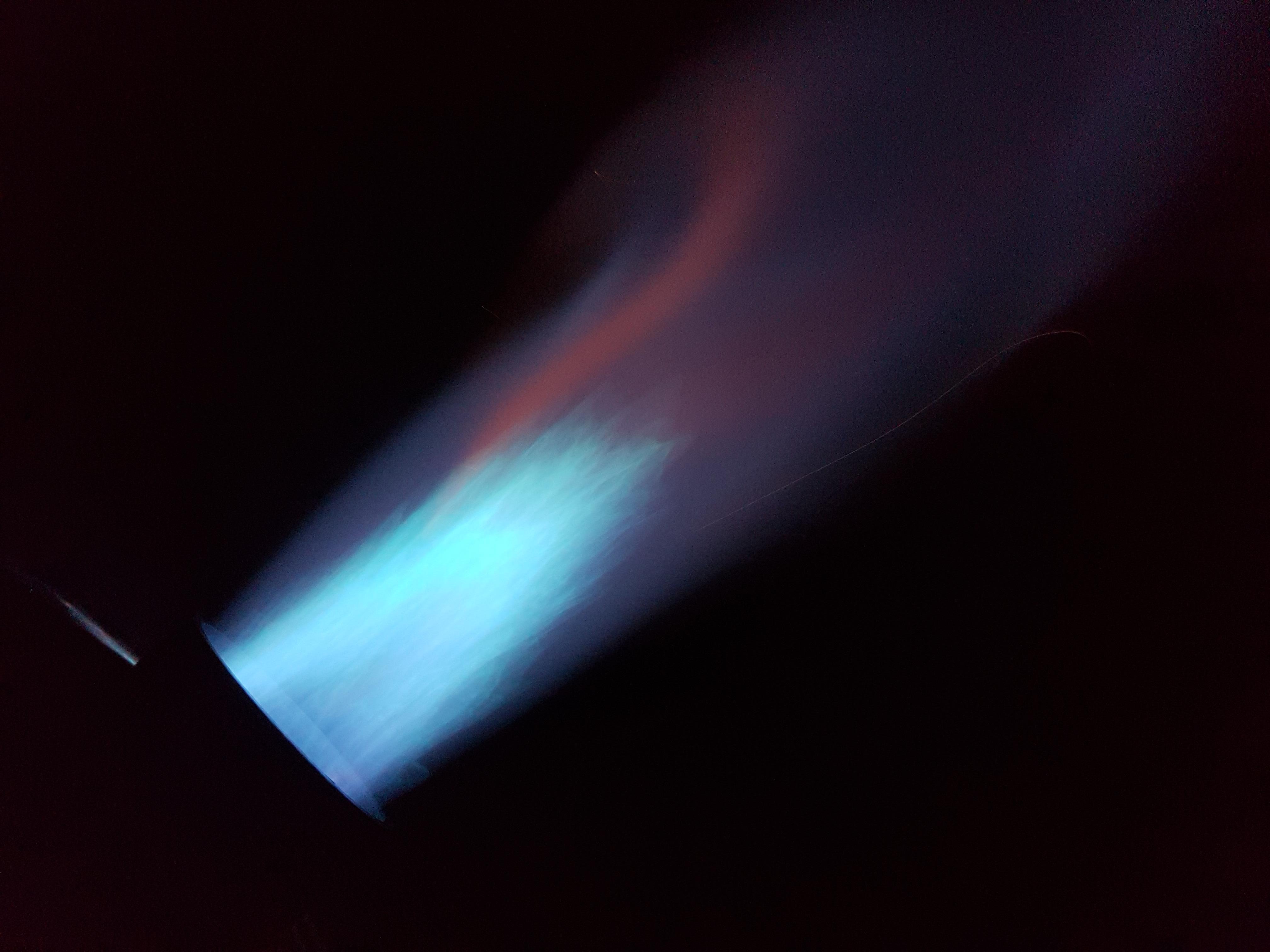
I made a new nozzle and did my best to align the parts. As far as I can tell (measured with a laser) it's straight and true. I honestly can't see much of a difference in the flames, so either my eyes aren't tuned for this or I have made no difference. Thoughts?
-
I would by no means call it disappointing, I expected nothing like this. I expected to have made som critical error at some point and the burner not working! I'll get started on a new nozzle and try to tweak the misaligned parts back into alignement. I'll try to move the gas tube back a little too, play around and see what happens. Thanks guys, updates to come!
-
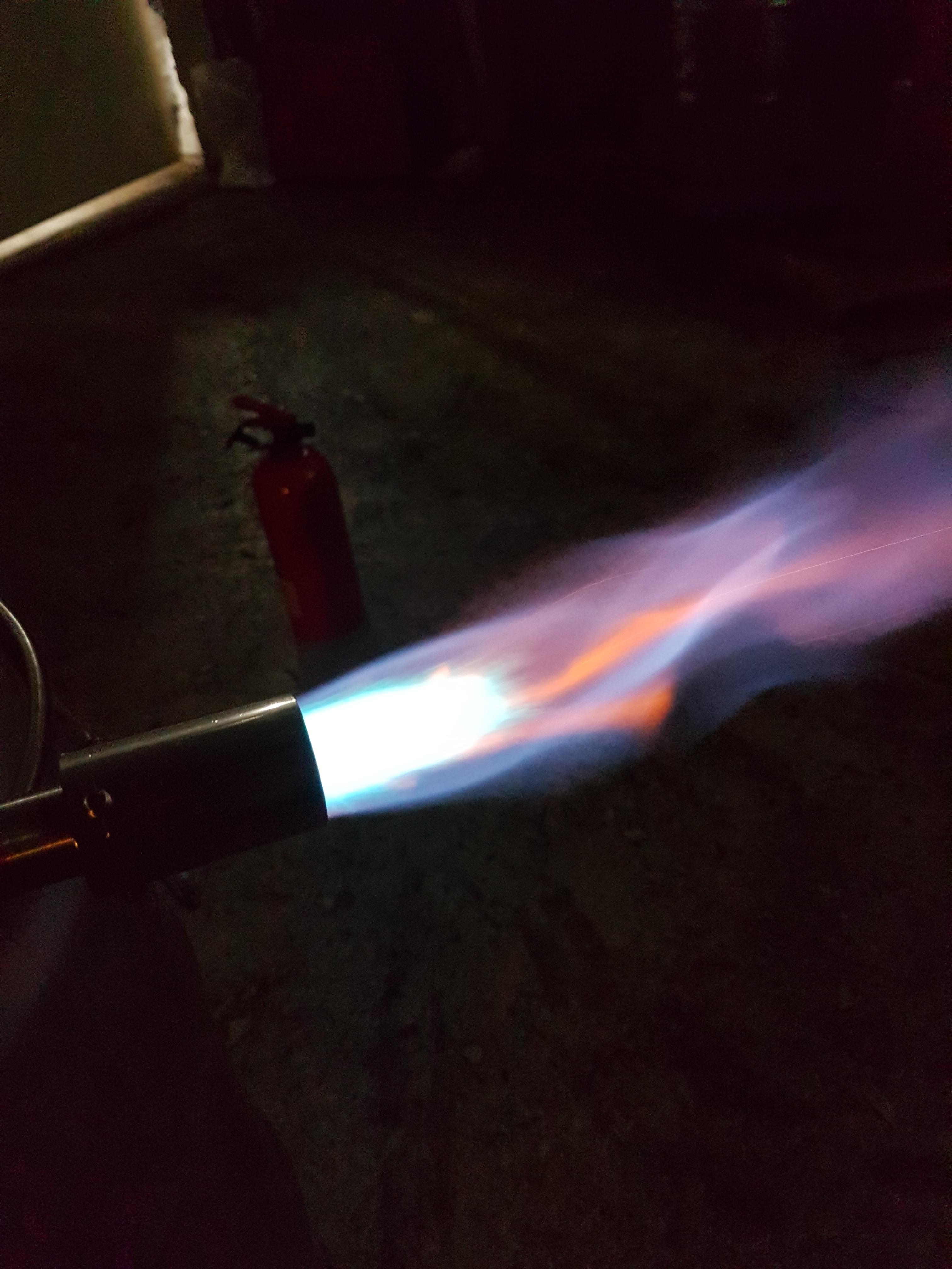
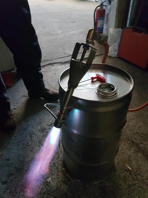
It works! That was the best flame I could get by adjusting the nozzle. I might have to redo the gas tube, it should probably be longer. But not bad for a first try! Thanks for all your help and input Mikey!


-
I read it all wrong, i was thinking of the mixing tube! Gonna get it done today and test fire it this evening.
-
It can be moved deeper, like I said in the previous post, it can be moved as deep as the opening of the mixing tube. When you say bevel the end of the gas tube, you mean the end where the nozzle sits, yes? The business end? The end that's attached to the reducer is already beveled. Is 60 degrees the correct bevel?
-
Almost finished (I hope). Couldn't find a suitable bolt of alumunium to make the choke plate, so I'll figure something out next week. I'm not sure if the gas tube is long enough though, at it's lowest point It gets the tip of the MIG to the narrowest point in the reducer, but not down into the actual mixing tube. As far as I understand that might be long enough, hope you can weigh in on that Mikey. Gotta find som parts for the gas too... I'm cautiously optimistic for lighting it next week! Have a good weekend!

-
I'm gonna keep on asking stupid questions, as the sizes of the pipes and nipples aren't obvious to me. I checked the McMaster catalog, and if I understand correctly, the tube needs to be 3" long and basically accomodate for inside thread for a 0.8 mm MIG tip and enough wall thickness to make threads to fit the saddle? I think I'll put a ball valve at the end and a 90 degree elbow off that to fit the gas supply to. Does this sound good? Edit: Or an elbow before the valve maybe...
-
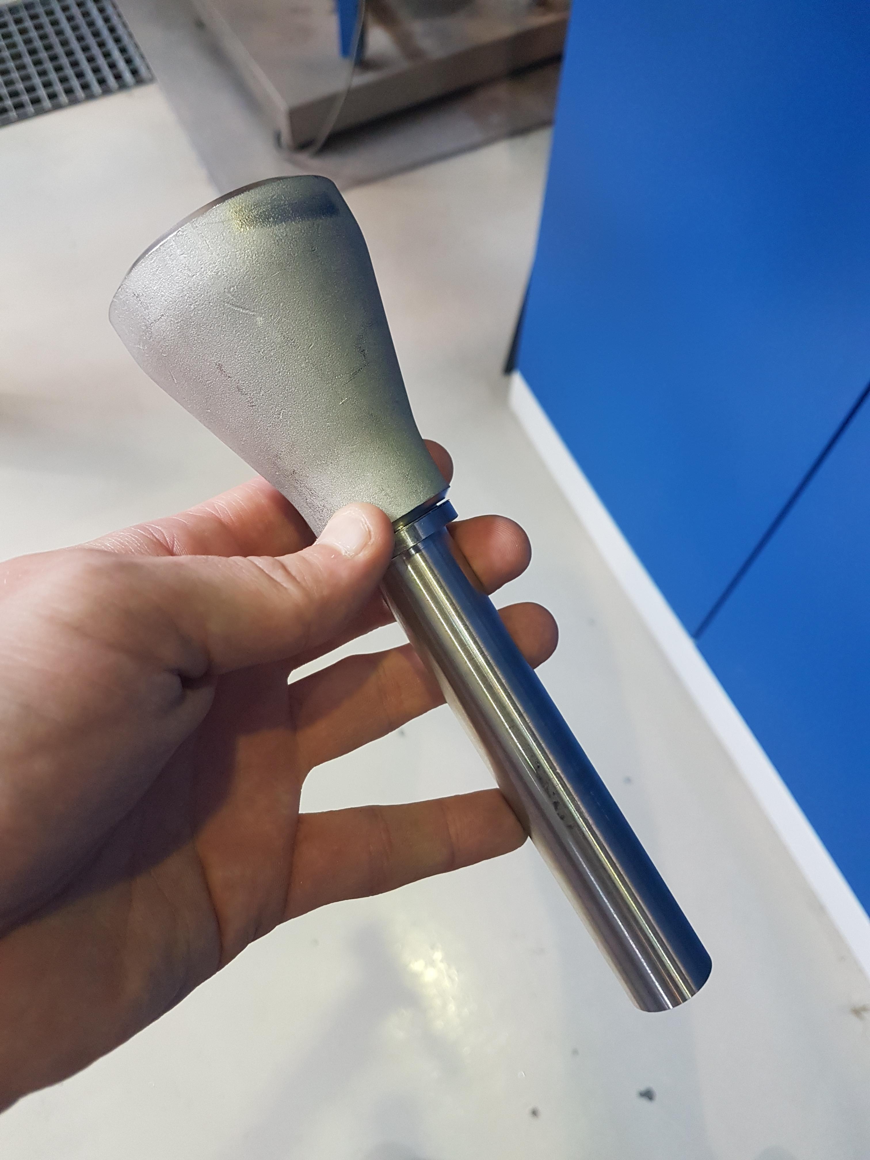
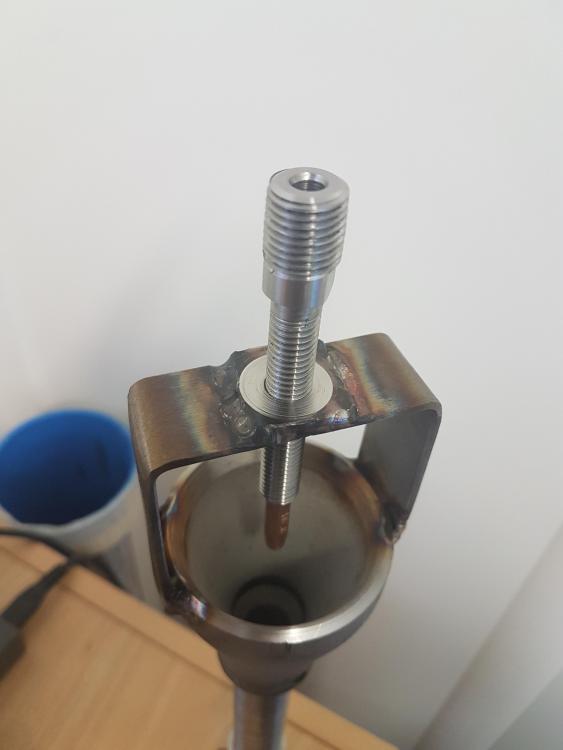
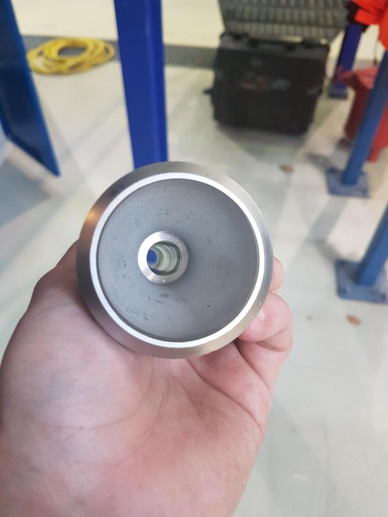
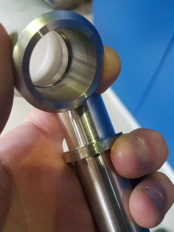
Update: I've welded the tube to the reducer, and it seems straight and true. As far as I can tell anyway. Here's hoping... I also beveled the top of the reducer and made the saddle. I'll get to welding the saddle tomorrow hopefully. Getting close. Need to find a suitable pipe for the gas tube, or just turn something on the lathe...
-
Put a 60 degree bevel in the tube, and the transition between the reducer and tube is near perfectly seamless. I'll weld it up next week, and then it's just a "simple matter" of making a saddle and gas tube... Have a great weekend everybody! PS. Sorry for the lack of pictures, my phone got smashed last weekend and the loaner phone's camera isn't working.
-
Update: I haven't been doing much with this project the last couple of days, been really busy! But I got the set screw holes in the reducer drilled and tapped today, so I hope to get the bevel in the tube made tomorrow, and weld the tube and reducer together. I'm thinking I might weld the saddle on to the reducer and then drill and tap the hole for the gas tube on the lathe, to get it dead center. It seems like a good idea on paper at least...
-
The thickness of the wall is 3.4 mm. OD is 22.3 mm and ID is 15.5 mm.
-
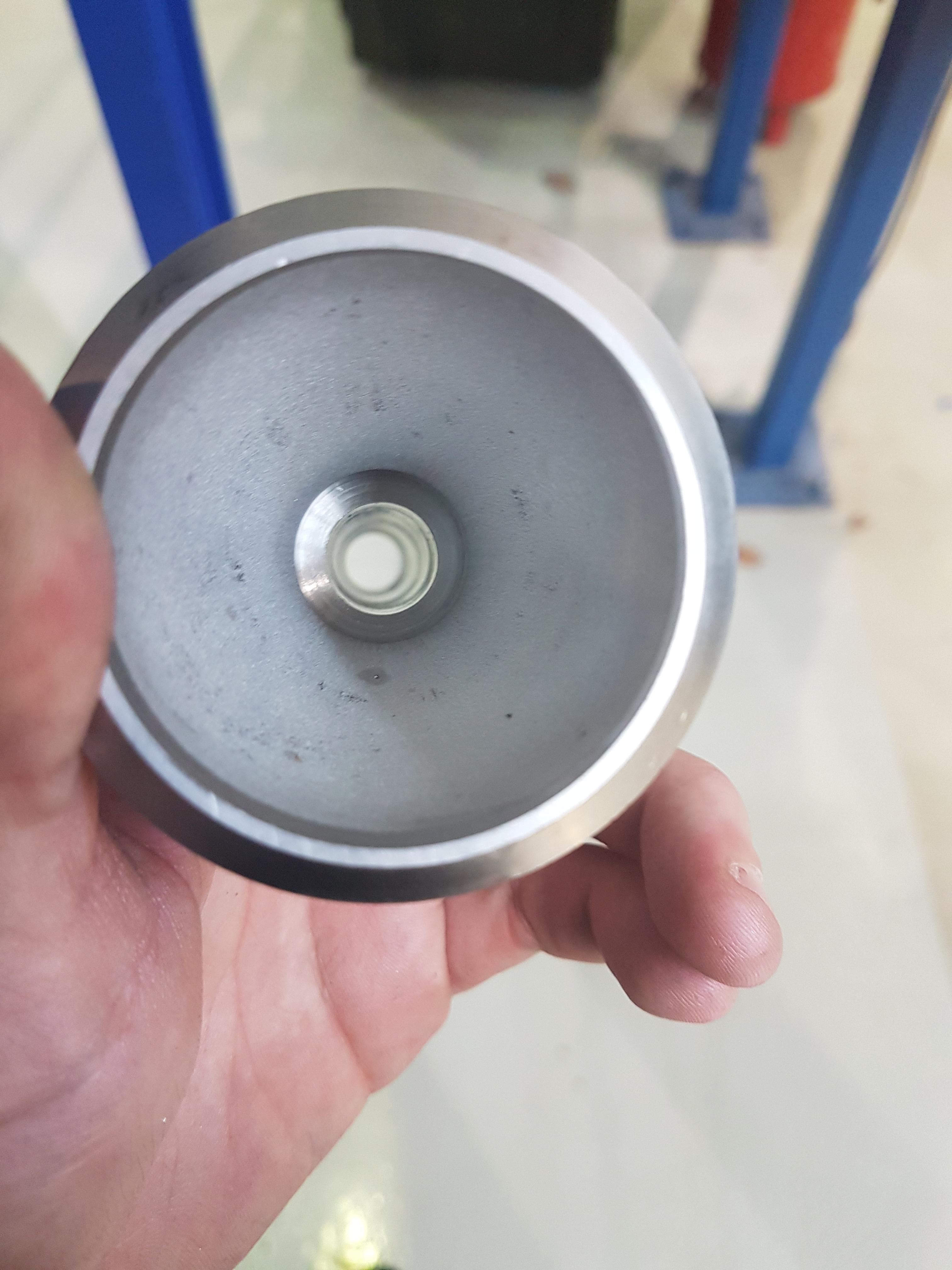
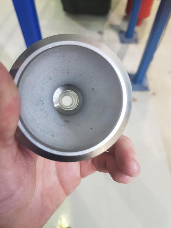
Update: Got the hole drilled. It's 15.5 mm, because that was the closest I could get to 5/8". I couldn't find a 16 mm, which would have been closer by a hair. Gonna put a bevel in the top of the tube so it's flush with the reducer. And put a bevel in the top of the reducer. The inside of the reducer has a glass blasted finish, should I polish that off?
-
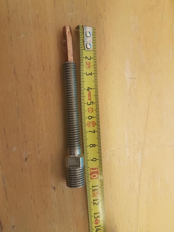
The tube isn't a tube yet, I have to drill out a center hole of 5/8" or the closest metric size as that's all we have available. As of now it's just a bolt. I've been away for a couple of days so haven't been working on it, hope to get the tube drilled out today. The OD of the tube is about 22 mm right now, I can machine it down further if necessary. I'll probably make the nozzle on a lathe as well.
-
Got the tube nearly done, just needs a hole through it. Hope to get that done tomorrow, feeling slightly under the weather today. I made a small shoulder in the small end of the reducer so the pipe will fit up to it and make it all straight and true.The fit of the OD of the pipe is pretty snug to the ID of the small end of the reducer. I plan to weld it at the end, but maybe it would be best to set it with set screws first. Time will tell... Stay tuned for updates.

-
I figured 2" opening on the reducer -> 1/2" size tube for the 4:1 ratio. But I haven't even started on the hole yet, so I'll find a suitable drill bit. So the tube's length should then be 9 x 5/8" or about 5.625 inches? I'm gonna cut it long so I have some room to fail. Thanks Mikey!