

James Bond
-
Posts
36 -
Joined
-
Last visited
Content Type
Profiles
Forums
Articles
Gallery
Downloads
Events
Posts posted by James Bond
-
-
8 minutes ago, Kaleb said:
I guessing some sort of kaowool and then,
oh, ok
thanks Sr
-
Regards
Your project is great
What material did you use to concentrate the heat in the box, and make it not warm the outside of the box
-
good morning
I was working on a design with a microcontrol and a pll that I found on the web.
I did not like that the card was so big and with so many elements but it is what there is at least in this first version
Try that the feed tracks were as short as possible to the micro, I think I'm going to generate a lot of noise or harmonics when my inverter is working.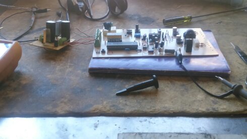
-
Digital control the head of my induction furnace ..... The induction furnace in its simplest form is a coil switched to a specific high frequency, and I say specifies because this frequency will depend on 4 factors 1 Working coil (tank circuit) 2 Our workpiece 3 Our capacitor (tank circuit) 4 Temperature Of all this will depend our frequency. Then we know that the frequency will vary by any of these four factors, The Digital Control must generate a frequency and must always try to maintain the desired frequency so that the max power is transmitted to the part, My card needs to condition signals and read data as well as generate a control in the inverter and detect signal out of pahse and I will design my card with microcontrollers and analog circuits and a PLL. There are many circuits on the web that show what I am going to do and if any of them serves me I will take it into account -
2 hours ago, the iron dwarf said:
2kw is a bit small to be useful for forging, I have a 15kw and that is still small
i know but i can't begin with a 15kw heater
-
9 minutes ago, Frosty said:
Welcome aboard James, glad to have you.
Induction heating is an old mature technology. 50-75 years mature? Guys have been making units for small scale forging and casting for decades. Using the magnetron out of an old microwave to make a jewelry scale melter has been a subject of Youtube, how to videos for quite a few years and I have a friend who built one in the 1980s and uses a version to heat billets for mokume gane.
The problems Robert refers to arise when people who don't know how they work try building their own. I hate to tell you this but reading what you've written here tells me you are pretty much at the bottom of the curve on this project.
You speak in the absolutes of a college student without the experience to know how little you really know. I'm not being insulting, we're all ignorant there is more we don't know than we do know, worse what we do know is probably mistaken on may different levels.
Right now you're just guessing, Grant Sarver bought components and said many times trying to salvage electronics was an expensive, time consuming path to failure building induction forges.
However for a college science project maybe. As a thesis? I really don't think so.
You have a LOT of good research to do before you start experimenting, just the boards are DANGEROUS.
Frosty The Lucky.
Jerry you need to follow this project.
because some day i will need your help
13 minutes ago, ianinsa said:Is true but we have to create our own way
please follow the project and nice to meet you
-
On 6/21/2017 at 1:22 PM, Anachronist58 said:
ny ridiculed Elon Musk for daring to call himself a "Rocket Scientist".
This switched source is only for powering the electronic cards and the inverter driver the power supply of the inverter will be another. The switched source for pc must be able to feed our analog and digital integrated none of these would consume a lot of current .... except for the driver for our inverter, then we will speak more clearly about this topic. As far as prices of switched sources in the market are from 19 to 25 $ to 450w I got mine from an old computer
-
First of all I want to separate my project in several steps
power supply
Digital control
User interface
Inverter driver
Tank capacitor coil circuit
Cooling method

POWER SUPPLY is necessary a power supply that can deliver different negative and positive voltages for my analog
and digital circuits that will carry the electronic card, it is important that this source can deliver several amps,
 this power supply must have a good emi filter and If it's tucked inside a much better metal box.
The EMI filter is to eliminate noises and high frequencies that are mounted in our line socket
 since we will be working with circuits generating electrical noise the filter emi is necessary
In my case in my laboratory I have a switched source of an old pc but still working I think it is what I need since its input has an emi filter and is high current has several voltages and is covered in a metal case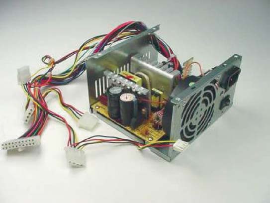 On 6/21/2017 at 12:19 PM, Anachronist58 said:
Mr Bond.
Welcome aboard. If you will add your general location to your profile, you may find that there are Smiths nearby who would be Very Interested in your project.
The system that you have outlined, with the capabilities that you have listed, has challenged and frustrated many who have come before you.
Welcome, and I wish you a good outcome in pursuit of induction heating.
Robert Taylor
Robert, nice to meet you
I am interested in creating a debate on this project
I have faith that everything will work out
We are in touch my good friend
and yes,i will add my general location
-
I will design an induction furnace of 2kw of power that will be able to reach 1000 or 1100 degrees Celsius, it will be cheap and easy to use for the user, it will be able to heat all type of metals, as long as they are small pieces, and will have the possibility of Control power. I have been reviewing and studying many home projects as well as thesis on induction furnaces and although I do not understand everything completely I think it is time to move to the experimental part.
Induction Heater
in Induction Heating, Oil forges, etc
Posted
Thank you my dear friend for the invitation
50KW is very powerful, could you send me photos of the manual or electric diagrams of the inverter to study it?
For now I follow with the design of my inverter one quite smaller than yours.
And with the driver that will activate the igbts
I decided to design the driver that will activate my inverter, I will start deciding which inverter I will use, I think I have in my laboratory all the elements to design a half bridge inverter, for now I will design one of half a bridge because I do not want to burn many mosfets or igbts
My driver design will be able to deliver enough power if necessary to my devices, so that they can turn on or off in a short period of time, they will also have to have different sources for each power transistor.
As I do not want to have noise or ringging problems in my gates, my driver should be as close as possible to my inverter.
and connect a good resistor to the gate.