Indianer
Members
-
Joined
-
Last visited
Everything posted by Indianer
-
Follow-up after I'd had a chance to cold down. Thanks to anyone who who took my reaction as what it was - a REaction. velegski, I had no idea the OP was that misleading. I thought it pretty much on point, given the title. In retrospect, mentioning the mini forge probably didn't help. Thomas, the wooden version based off real things is a great idea. In fact, I had long planned to set aside a tapered mid-process blank in mild steel. Makes it easier for me not to forge anything down too far before the grinding. And frosty, while I appreciate the offer of continued support I think that if my answers were "pretentious" to you, then maybe you should have asked different questions. All my "talk" about what I planned to do with the shots, that unfolded AFTER I'd been asked to explain. Anyway... still offering to buy photographs as described. Cheers
-
Alright. Obviously my inquiry here wasn't appreciated. Thing is, much as I tried not to lash out, I'm gonna go to bed feeling like xxxx after another day being what feels like assaulted and ripped to pieces in spite of all politeness and demureness I could possibly muster in the light of being once again confronted with a deeply routed elbow mentality. I didn't come here to ruin anyone's day, I didn't come here to impose or force myself upon anybody, nor did I do anything even closely related to anyone. And yet I feel... like xxxx. Mostly sad really. And disappointed. Not because there's not gonna be anyone willing to help out here, but because I came to a forum that once had the purpose of helping people and apparently has fallen into an attitude of forcibly having people believe they will forever stay too stupid, lazy, incompetent, uneducated and ungifted, even unworthy of attempting something new. That makes this forum just another place like the rest of the world. Good night folks. Mine is gonna be crappy. Again.
-
Right now I'm really just looking to buy a photograph from someone who makes those regularly...
-
Yes, the long handles on these make them Hand-and-a-half swords. I personally find those appealing too. When I get to forge some for myself they'll have a blade length of 29-33'' (74-83 cm). The counterguard though does not seem to be what I meant by "flare" - the Lothric knight sword has a pointy wide section in the blade just above the grip. In my browser I can see that right here in the thread in the video preview above. I mentioned those flares because I wasn't quite sure at what point to put them in - I believe I found someone put them into the tapered "blank", so they seem to be established before the edge bevelling, albeit blunt like the rest of the blade. Would be a nice additional info in the drawing. As for the statistics, these are for the Seraph Aegis prototype linked in the vid above: Overall length: 45.5 inches Blade length: 32.5 inches Blade width at widest point: 1.5 inches tapering to 1 at 4 inches from the tip Blade thickness at base: 3/8 inches tapering to 3/16 at 4 inches from the tip Cross width: 9.25 inches Grip length: 10.25 inches POBalance measured from end of grip: 4.75 inches Weight: 3 pounds 7 ounces
-
Hi Thomas, double edges straight longsword with or without fuller, preferably with flares (that what they are called? The pointy wide sections along the blade?). Along the lines of these:
-
Good evening Frosty, I tried to keep the OP brief and therefore didn't go into the details. I write. Whatever I learn, by hours, days or weeks of research, theory or practical, I put in personal notebooks. And I like to pretty them up with artful drawings, long as they get something valuable across. To that end I sometimes convert photographs or screenshots to gray-scale images. I could show you some, pm me if you want a sample. They are a lot of work. And still, I like doing and/or having them. It's a labor of love. I won't argue you have a point. I could extract much more info from images if I had your knowledge as well as mine. But I also have mine. And in days-long sessions I found one thing - I am getting nervous and confused about the physical blade-making process where I don't need to. In the last forging I did I hammered the blade out and constantly checked...just too much. Because I didn't have a clear gameplan. Getting the contours right, tapering it, getting the bevels in. I tried to do all that at once, which was an unpleasant experience. Naturally the processes are interdependant to a degree. But I still should know what exactly I'm working on right now, or I just get lost. This particular drawing should remind me of the following: Lines can meander a bit. A blank like the ones above doesn't demand perfectly level edges. And I don't start bevelling anything before it got a blank that has the strength I later want at the spine, or along the fuller, and tapers and thickness and width. It's not perfect? OK. I'll do some grinding anyway. Is it good enough to reliably clean it up in the grinding once the bevels are in? I should ask myself that when I hold it in hands. Now I could simply put all that as text into the notes. And I probably will. But I'd like to do it as a capture, not a paragraph. Simply because. It would make me happy to have it as a picture. Those renderings were simply meant to show exactly what angle the photographer might take so I can work with the pics. All that said everyone here is more than welcome to point out more things I could watch out for, or should take care of. But that is like asking a swimmer "Ey, how do you move through water?". I would't do that. velegski, I never heard of either of them - thanks for the reference! That book is worth checking out, I'll look for it Best, Indi
-
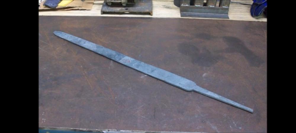
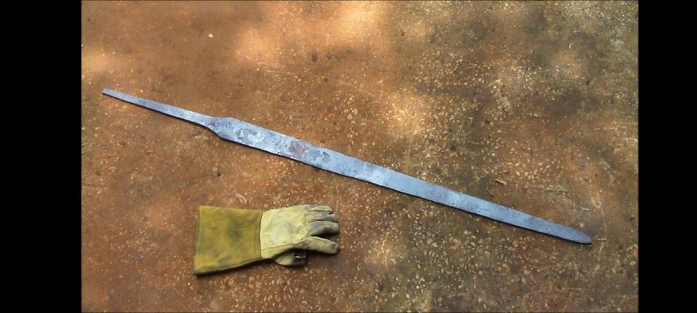
Weell... it doesn't really matter how the blank comes into being I guess. What I like about the un-bevelled shot is that from there it's good to be processed further - bevelling with the hammer, or grinding them in, as one wishes. Creates a clear succession of worksteps for the beginner. Of course one can get there with the hammer. Might even be valuable to see where one might call that forging done. So if anyone happens to hammer out a sword in that stage, I'll be happy to take a look
-
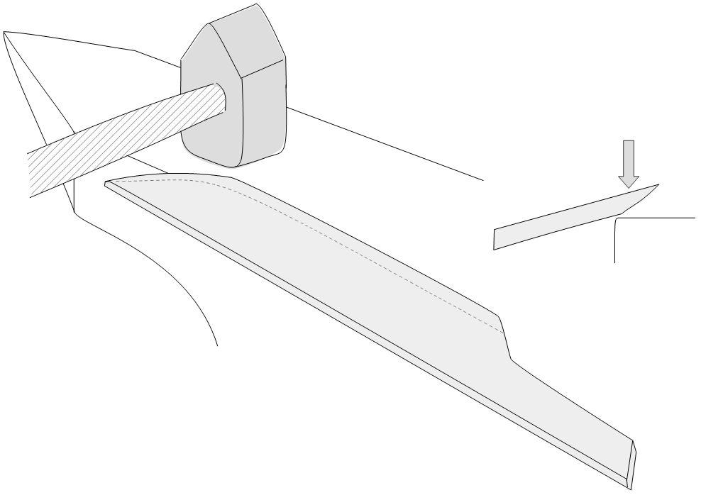
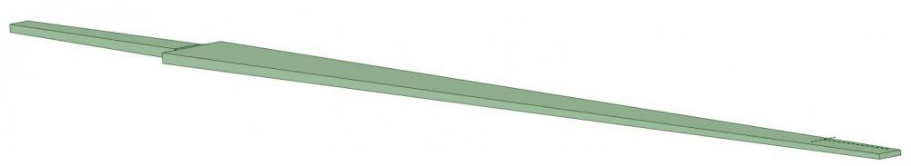
Hello guys, I've been busy watching Brother Banzai's videos again. Thinking about building a mini forge press myself I found some profoundly meaningful frames. Those are blades he either just finished forging under the press or, one step further, hammered the edge bevels on. The blades are scaled, rough, and thick at that point. The lines a bit wiggly. And yet they are perfectly fine, tapered and ready to be taken to the rough grinding. This is an important message and I'd like to capture the nature of a blade blank in that condition for reference. And while I'm at it I'll make a beautiful concept drawing from it. If someone could help me out with the photographs that is. What I'd love to have is a shot from right above the blade, taken from a distance so as to minimize distortion. And maybe one at an angle so the thickness becomes clear. Like these... > A 1-handed blade fresh from the press maybe. It would be an extra perk if there were flares along the blade. > The same blade fresh from the edge bevelling. The background would be cut away, it doesn't matter. Some light to make out the surface texture is more important. What's impractical about the screenshots is that the blades lie in an angle to the camera. I can not rotate them digitally. Plus I had hoped you could produce a higher resolution...? This takes time, so I'd also like to indemnify the one taking the pics. Can't reach Jeffrey Robinson himself. Let me know if it's possible All the best Indi

-
So, another way to hang the helpers. Helper on the short side of the table, suspended in the long frame right beneath the table top plates. Red is 30x30x3 in 40x40x4 in a cut-off 50x50x4. I have no confirmation yet that red telescopes into 40x40x4. In general though, this gets it a lot less complex and probably just as difficult to align in right angles. Fine-tuning after I have confirmation. A good thing is, I now can place the legs yet a little farther apart.
-
So, I found weights for the bars and calculated the parts again. While the frame is lighter than Glenn assumed, all components could still be taken down a notch. ATM, weights per [kg]: H-sections 6.9 Bottom Supports around H-section 3.5 Top supports 7.3 1 Expander ~14 Long side of top frame, with expander bearing 9.1 (still haven´t had an epiphany on how to suspend it simply inside the top long frame without loosing the "plug-in connection" there.) As Glenn said, steel part of top plate 23.4. Best divide this into 2 sections. Reducing the thickness means the holes get too short..I guess? Planned to modify a few clamps like he does at 8:04. I found smaller tubing with the same wall thicknesses which should do the trick. 40x50x3 & 50x50x4 ---> 30x30x3 & 40x40x4 (30mm =1.2'', 40mm = 1 3/5'') The rectangular tubing at the end of the expander(s) can be aluminum. No reason for it to be heavy or bomb-proof. I´ll see about another suspension system for the long bars... Anyone have a recommendation what weight I should aim for so I (80kg) can with no trouble apply a little force to something clamped onto the table/into a vise on the table without it shaking? Basically, what you´d expect of a good workbench, hobbyist size.
-
Made may day, had a hearty laugh there^^ Although that tool stand like like a well inhabited retirement home for tired tools... :/ You mean like the red thing? Bought! For those with the space for both, sure. I figure, a heavy one will do for all lighter work too.
-
Thomas, a couple years, some years, xxxxxx, longer ago than I like to think I first came here to ask about what steel to use for armour. All I had back then was Jim Hrisoulas book on swords. It might just have been You who pointed me to the ArmourArchive. I´ve since never stayed off the archive for more than a few days. All I could do so far is learn about how to make armour and write on a notebook on it. But still, without the archive my world would pretty much end. I´ve not had the pleasure of mingling with like-minded folks in person though..no SCA or HEMA, not even conventions. Which I regret btw, but cannot change. Ugo is a legend on the archive, a myth shrouded in enigmas. I´ve only see a few pieces, but they were stunning. He appears rarely though, at least during the last few years.. I do like women, very much so. And I´m really not opposed to the thought of an Elena for my Damon (Vampire Diaries...). But I can neither afford them nor will I suffer being ever again restricted in my craftsmanship. One has to make decisions, this is mine. I am wed to my stakes, vise and angle grinder. And soon a table. Being a lone wolf is better for me than being a sheltered hound.
-
Sure thing! Intended to to leave conducting areas blank, including all of the surface and the paths I would like my current to run...where it actually does run is another story. Oh, and that´s a non-issue. Now and forever. Some pretty colour might be nice though...I´m thinking black Alright, let me try: Jewellry hot work (hard soldering, small oxy/ace or just oxy/propane torch like smiths little torch), small-scale lost wax casting. A sword pommel is not considered small anymore. Any filing and polishing that might be needed. Leather work as far as leather armour goes - cutting, embossing, riveting... Small scale welding projects like this: Mid-sized welding projects up to the size of armouring stakes (shaft of 1'' square with diverse heads, the largest being ball stakes of ~3'' diameter.) The largest welding application I can think of is making the frame for the table I am planning here. It won´t be my everyday business, my interests are armouring and sword-making. But this should be possible if push comes to shove. If I ever plasma-cut something, it will be thin sheet. I do not intend to support a piece of rail-road track on the expanders and cut it into an anvil. I do, however, have a RRTrack anvil and it would be niece to have it seated on a table while grinding a saddle-shape into it, not down on the floor. All thing armour related: Cutting sheet, maybe on a beverly 2 shear, or with a nibbler. Drilling holes into the sheat (vertical drill or drill stand), support a manly buffing motor on the table. Clamp things into a vise and cut them with the angle grinder, or grind, or polish them. It´d be nice if I could seat a saw into an expander, as seen here at 12:15. Not much of a wood worker though. I need the main section to withstand the shock of some armouring work on a stake. I plan to weld a stake-table for this, on this very table. But still, this one must be robust enough. That´s all I can think of. So...Can I go down to 5/64'' (12ga, 2mm) for the inner tubes in a tube, including the legs?
-
Hi Glenn, thank you for this!! Those numbers are shockingly beyond what I had in mind. Technically, the tubing for the legs is 40x40x3 and 50x50x4 (short segments). Still, that needs addressing... I´ll look for lighter material. What about the wall strength though? Can I go down to 5/64'' (12ga, 2mm)?
-
Take your time Frosty, thanks for getting back to me. And yes, it is a rabbit hole, isn´t it... The intention to make it modular alone, so one can simply clamp single components under the arm and carry them around, makes it all so much more complicated. With expanders in it get´s even more interesting, no matter in what shape they come. Curious what you come up with. So long, and thanks to all Thomas and Glenn ruminating here with me!
-
Glad to hear, and good to know - thx for the warning! I am trying to wrap my head around your suggestions. I seem to hit to limits of my foreign language aptitude though... Starting with this: 1) What is NS and EW? 2) Basically they already are tubes within a tube. Do you mean I should let the outer tubes hit the ground, instead of the wheels, and dispense with the screws? If so, I´d probably still need a jack to lift the table, unless I get you wrong. 3) If supporting the inner tubes via bolts through the outer tubes: I do not think even my supplier can drill precise enough to get them exactly level on all 4 legs. That means, the table would wobble without screws to adjust for tiny height differences to the ground. Even if they were level, as soon as the ground is not I´d need the screws again, or another means to equal out the air space beneath the feet. If feel like I´m not getting something here, sorry about that :/ Maybe. I have an idea that seems to get close. Will read it another few times later. First: You are suggesting a way to make the table foldable, are you? And I´d end up with the table top pretty much hovering above the ground?
-
Frosty, I asked for advise and criticism and am thankful that you took the time for that - it´s alright. I am sorry the pictures are so hard to read. They have been photographed from the same interface I use to work on them...although I can rotate and zoom. I have no clue how to transform that into blueprints.. It´s been a while since I had to think of that. Indeed I didn´t here. Well, let´s just say I´ll keep welding down as soon as anyone else might be affected. Exactly, the cleanup is nasty. Plus, things I weld are usually small, like single screws or the like. At least for now. If the first tack weld doesn´t take, the brushing around it will usually break the wee weld...flux core is clearly more useful for larger stock. The blue box? Nah, that´s just the outline of my welder. Wanted to see how it fits. The hydraulic presses are not shown, I had bottle jacks in mind (the 2t variant). The site is German, but perhaps you know these things. I´ve never seen one before and only began searching for that because the dude in the video used them to lift the table. I am not aware of any legal issues here, they seem like typical home-tools for guys that like to change tires themselves? I will have another look at the scissors jacks. I assume, you mean a things like these? They seemed like a nice solution to the same problem, only much slower and bulkier in action. But..I don´t know either of them personally "Expanders"- I just did not know what to call them I can see your point here. It is a complex structure, and each connection that I do not want to weld so I can disassemble it all into carriable parts leave wiggle room that concerns me a bit. This would be especially true for the helpers/"Expanders". In defense of the telescopic system: Since the telescoping parts can simply be pulled out of the tubes under the table, cleaning is made easy. There remains a 2 mm gap between the larger tubes (50x50x4mm) and the smaller ones (40x40x3). That gap distributes to both sides, so, if the inner tube were centered, 1mm space to each side inside the telescoping tubes. All tubes have an inside welding seam, which reduces wiggle room a bit. The vendor tested it, they can still be telescoped though. That said, I will try to down-engineer the bearings without sacrificing modularity... that will take some time. Got me. I have probably underestimated that also. Not yet a reason though to abandon a quality workbench that can serve as welding table. 6mm, 1/4''. I figured if I chose it much thicker it´d become uncarriable. The larger top plate segment is in it´s current state 29x23'' (74x59 cm) - not too large. That´s another reason I planned 2 segments - to cut down on individual weight. Choosing one in Alu was also more of a weight consideration. I have no clue how heavy that layout would be in the end, just figured it´d be plenty for an ambitioned hobbyist. I´ll learn about the weight when I assemble the shopping list for steel tubing. What´d you say? Still forgo the aluminum for a main plate due to reasons of practicability? That´s the plan. This would be the leg segment - one for each side. Only the green parts are welded. They grey bars on the bottom have to slide, but are welded to each other. Regardless of any changes I might still make to down-engineer it, the crossbars and bearings on the top would be another segment - simply slid onto the legs and rested on a bolt Alright. I´ll ponder some changes now Thanks so far guys!
-
Glenn, you helped me realize the space to clamp things was limited. I rectified that now and added corner plates to be welded onto the main plates. They are large enough to hold the rotary table for my vise (blue).
-
Hello Glenn, thank your kindly for the tips! I never would have thought about arcs in the sliding sections until it were too late. Also, I like the circuit breakers. German wall sockets are all secured with rather sensitive breakers, but meh..why not double on it. Adds a factor of curiosity to the build I never ever do any grinding, welding or cutting without my trusty mask. Never have. Thus, if the smoke takes a minute to clear the apartement, I´m fine with it. So far I´ve only tried self-shielded FCAW, to forgo the gas bottles and cut down in expenses. I plan to move on to TIG, that seems to be a lot cleaner overall. Debris? Just like my every-other-day-wiping the floor. Should be setup in a suitable corner, sure. But it´s true. Larger welding operations and using an angle grinder for whatever are impractical and usually impolite in apartments. Now I can rely on a basement to do that. Later...I´ll see. I am building for the future here, since I do not plan on staying where I am. And I need a workbench for all things one can with no trouble do in living spaces anyway. Once I have a proper, own garage or workshop, I will move all the projects there and only require one work table. So why not build it up to the task right away? Another note on the table: In the second-to last pic, the bottom view, there are bolts securing the long top bars of the main frame into their sockets. Without these, one could easily pull the leg frames apart. I might have missed structural aspects like this one elsewhere..feel free to mention!
-
Hello all, I have spent some weeks on designing a welding table and would very much appreciate some advice on it, before I commit to steel. I need it small and modular enough to be able to follow me in whatever apartment I might still move (Yes, apartment, get over it!!). Should be sturdy enough to handle workshop-scaled challenges of course. I need something to do some basic jewellery or leather work on anyway^^ I took inspiration from here and here. The latter video shows the hydraulic presses I´d like to use as well. This is it. The screws allow me to lower it to 86 cm height. There are some utility bars attached already. These are not definite. Crossbars for the hydraulic car-lifting-thingy included. 96cm (38.8''/ 3,15 foot) tops seems much.. but I simulated different heights with a crude setup, and found this to be what I´d like to work on while standing: "Expanders" pulled out. Strangely looking ends they have, but I can install drawers between the bars. Might still tinker with the height though, to facilitate larger drawers: Legs, Feet and Bottom support for one side. Where there is no screw, there is weld. The tubing is 40x40x3 and 50x50x4. The vendor checked if they can indeed be telescoped. There is an inside weld which bears watching, but it seems to work. Top supports. A separate module, just slid over and suspended on a welded-on plate or a thick bolt (visible on top-right leg): Long bars to bear the actual top plate, again just lied in place. To get the legs farther apart, I had to rest the right expander tube on the inside of the leg; hence the undersized crossbar. Those prominent screws are for tightening the expanders firmly in their bearings: Of course, I could have put the expander on the outside..which first I did. But then the legs would only have a distance of about 30..something cm on the inside. Making the entire table wider would have solved the problem, but as it is it has already 65cm depth, which is quite enough for an eating table. The expanders simply slide into the tubing. They could hold a plasma cutting grate, and wood plank with slit, or...whatever I am not thinking of. The holes in the top plate (6mm, 1/4'') are layed out in a 10x10cm pattern, threaded M10. Might not do the threading myself though. The short segment of the top plate is planned as Aluminum, to weld stainless steels. This should avoid rust forming due to impurities welded into the seam (just read that this was a thing...I don´t even know if it is :? ). So, I have been working on this for weeks. Please, let me know what errors or shortcomings I do not see. There usually are some... Also, what you would consider an upgrade on such a table, please share. Thank you! Best, Indi EDIT: If the pictures dn´t show, try this link.
-
Thank you so much! Now I can move on untroubled
-
You were right, was strenuous enough as it is! Got a few things going on here. I just noticed that, duh, I made a single-edged blade. I intend to quench in canola oil, vertically. Should I precurve it? All the knifes I see hardened on Youtube are not precurved. They seem to come out as inserted, thus I never thought about this. Then again, for longer things like swords it seems to be a thing regardless of a clay-coat (katanas only)... EDIT: This is the comment that got me thinking - The author does not distinguish between sword or knife: "My experience with marquenching low alloy, single edged blades of 5160 and O1 is that they lose appoximately 30% of their curvature quenched edge down or vertically, point first."
-
Hello guys. I had to heat it up one last time for changes to correct a minute curve along the axis with two hammer strokes. To prevent new scaling I strew soap scrapings over it. Soap baked on tight, but I don´t think it scaled again...which is good. Used these two heats for normalization then. Now before I heat treat: I want a portion of the spine serrated and a groove in the front third of the blade. I wish to introduce these with files. Should I do that before or after the heat treating? Could imagine it a source of bending, or the teeth to bend themselves, which would be hard to correct. Thank you!
-
Done that - you´re right, he makes it easy to see how he strikes. Thx! I think that´s it - I didn´t use half face blows on the far side of the anvil, rather full faced. That´s probably why I couldn´t taper the blade there. Felt a little wonky as well when I attempted that, half faced blows would have been much more stable in terms of hit and miss. I will give it a try when I pass by the smithy next time
-
So, learned a few things...feels like learning to cross a street again. I had severe trouble getting the blade simply straight. Ended up buying a 20 inch aluminum ruler to check during the forging. I am satisfied now. What I wanted to bring up: When forging the bevels along the belly I worked on near and far edge of the anvil alternatingly, always pointing the belly to the edge and laying the spine on the anvil. I seemed to be unable to create an actual bevel on both sides. Only one side had hammer marks and was slanted, the other remained straight. I finally got both sides slanted towards a midline, doing it the way shown in the pic: Did I do that very wrong? I mean...it worked after all. Thanks!