ReactorForge
Members
-
Joined
-
Last visited
Everything posted by ReactorForge
-
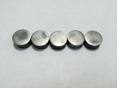
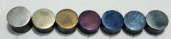
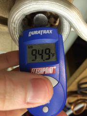 Temper temperature image
© ReactorForge
-
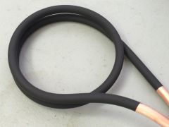
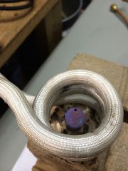 Temper small working coil image
© ReactorForge
-
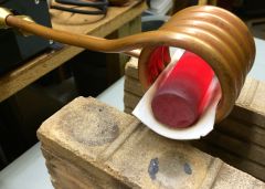
 Temper results image
© ReactorForge
-
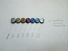
 Temper results closeup image
© ReactorForge
-
-
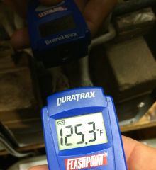
Iron Dwarf, Yes you are correct once carbon steel reaches 1200℉ to 1400℉ depending on the makeup it will become austenitic and loses its magnetic properties. The short answer to your question is yes, one of the items in the design goals is to develop a low cost automatic optical pyrometer for measuring and feeding back temperature data to the forge for the purpose of controlled heating applications. The control board already accepts such input and I have the parts and theory worked out for the pyrometer. If that doesn't work out you can use a thermocouple. Which would also be useful for temperatures below the point at which black-body radiation emissions are in the visible wavelength. Unless I also couple it with infrared detection for that range, lots of ideas floating around that right now but there are to many other things to focus on for the time being to get into that. The forge will have an input to accept control from such devices. Brilliant, I'll have to try that. Isn't sodium silicate an intumescent (swells in heat), pretty sure I remember it from a product or experiment that expanded with heat. Either way like you said it really should only need to stand up to radiant heat and occasional momentary contact. And getting the fiberglass sleeve to slick down to the tube would help a lot. It seems to want to bunch up and separate from the tube then when a red hot work piece touches it with no copper behind it to keep it cool it melts instantly. Did you come up with that or is it a common solution (in certain circles)? Yes it does, I had to scrape it off that bar with a razor which is not good because the little fibers float up if the bar is still hot right into your face. It's not asbestos but it's still a dangerous particulate. And as you indicated, it is a one time use thing. After heating it because brittle and breaks down into individual short fibers. In a way the whole point is a bit moot because the forge can detect and deal with shorts. In fact, I was using a copper bar to short out turns in a large coil the other day to focus the power down to a smaller area. It automatically retunes to the new resonant frequency and continues to operate as long as all other parameters are within limits (current, temperature etc). I just don't like the sparks, they make you jump and could cause you to drop the work piece. I've got a coil with baked on Rust-Oleum 2K℉ heat resistant paint I'm going to put through the ringer. We'll see how it holds up, not getting my hopes up. If I use a coating of any type, heat resistant or not I think it needs to be pretty thick to stand up against the mechanical stress of metal hitting it constantly. http://www.iforgeiron.com/gallery/image/38245-induction-work-coil-heat-resistant-paint/
-
 Rust-Oleum 2K℉ heat resistant paint, baked onto an induction heater work coil.
© ReactorForge
-
Absolutely, rolled up and inserted into the coil or just covering the bottom half of the coil so the work piece can rest on it if you have a horizontal work coil. I have some ceramic fiber paper that I got to try just that. Like this: http://www.iforgeiron.com/gallery/image/38244-125-bar-in-225-id-coil-wfiber-paper/
-
 Using ceramic fiber paper to insulate a 1.25" bar while it rests inside a 2.25" induction heater work coil.
© ReactorForge
-
Dave, If I end up using something like that I will most definitely make it available in smaller quantities.
-
Found some on Alibaba that appears to have better performance than fiberglass sleeving. It's made of amorphous silica not Alumina-Borica-Silica like the 3M stuff but still better than the cheap glass. It's only sold in bulk obviously, which is what I was looking for anyway. Good quality high silica sleevings "Our High silica sleeving is composed of continuous filaments of amorphous silica, the materials are capable of operating continuously at 1000ºC and at up to 1600ºC for limited periods, they will not melt or vaporize until temperature exceeds 1700ºC, and have a high resistance to thermal shock."
-
Tommy, it may be. However those machines have a lot of discreet components so trouble shooting would be a challenge. I might be interested in fixing it for you just to establish a benchmark on the level of repair complexity and rate of failure in commercial units. I'm not really interested in owning a commercial unit when I'm making my own. PM me if you would like to discuss it, I would do parts only and estimate before replacing anything major. Yes, I am doing that already. There is a bluetooth module in this one that was communicating with a Processing application to log data and graph it as well. I don't use that application to send commands much anymore since the hardware user interface is working, but the layer is there if it's needed. iron d, This unit runs on 240 Volts and can be set to use as much or little current as you can safely deliver (up to about 100A). In the video the current never peeked above 34 amps which is on par with an electric cloths dryer or a welder and would be the typical operating range for the final product. It could be easily modified to run on 120 Volts and still performs very well. I run it on 120V often when I'm testing new code. I know I you haven't seen it yet but I have plans for a 120 Volt version that uses power equivalent to a personal space heater (1400-1800Watts). In the video below I wired a custom, high current 65A circuit in Daniel's old shop (not typical for a 220/240V single phase circuit). This was the first version that operated standalone and did not have current limiting capability beyond the preset matching transformer ratio. Wide open it would suck about 85A so he had to be carful not to run it without a load. Daniel did not have access to 3 phase power which was the reason for needing high current. Since then I have made improvements that allow the forge to make better use of the low end power (when the work piece is cold) and control the current once the piece is heated up sort of like shifting gears. This current control also allows you to use the forge on any circuit and set the maximum current to not exceed what the outlet can provide. https://www.youtube.com/watch?v=fOJRu9ayc24
-
You can do a surprising amount with 1Kw. Of course it won't blow your socks off working with larger material (unless you lick the MOSFETs while holding your ankles). In my early tests I had a MOSFET version that ran between 500 and 1300 watts, it easily heated 1/4" stock to working temperature and beyond. It's all about impedance tuning, ensuring your work coil is optimized to the work piece ensuring you make the best use of the power available.
-
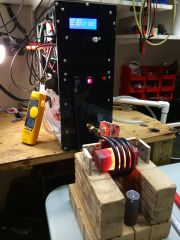
 So... black absorbs radiant heat. Didn't think that one through.
© ReactorForge
-
Hey guys, I apologize for not replying to all the PM's and questions yet. I've been burning the midnight oil for the past few weeks getting the beta model up an running. This project will be open source so I've been working on setting all of that up as well. That means I will not be selling plans, the plans will be free. I'll loose a bit of revenue there but I'll gain a lot of community involvment, insight and momentum. I know that the kit will be worth it to users who are interested in more than just tinkering. There is a xxxx of a lot of work that goes into sourcing parts and there are a lot of parts in this machine. Single pricing will likely be more than the cost of the kit. I've already implemented a few of the ideas I got from comments here (I think they were from here at least). For one the case is completely sealed, there is a 120mm heat exchanger inside the case that circulates air cooled by the water cooling system already present. This was also in response to me having to swap out the control board in the prototype Daniel was using, the conductive metal dust that it was covered in shorted out the microprocessor and PLL pins. This should greatly prolong it's life and reduce maintenance. I've also added a 16A solid state switch (fused at 10A) to automatically control a pump or valve based on internal component temperature (there are currently 4 thermal sensors in the machine). Now that the beta unit is mostly complete I will be focusing on content and documentation. Here is a photo of the first beta control boards being assembled. http://www.iforgeiron.com/gallery/image/38230-beta-assembly/ Hot Stuff: http://www.iforgeiron.com/gallery/image/38231-15inch-square/ http://www.iforgeiron.com/gallery/image/38232-05inches-by-6inches/ Stuff that shouldn't be hot: One thing I will need to change is the color of the case, at least the front. Although black looks slick it absorbs way to much radiant heat. http://www.iforgeiron.com/gallery/image/38233-black-is-hot/ OMG VIDEO! In this video the induction heater is running on 240V single phase 34A at near unity power factor (.99), it's capable of running at 3 times that capacity (and has). Most induction heaters that run at that input power level (7.6 to 8.2Kw) are rated at 15Kw (oscillation power), they also do not run at unity power factor but closer to .6-.75 or worse. So although the apparent power (input) is around 7-8Kw only about 4.7-5.7Kw of that is real power (doing actual work). I think I prefer results based rating over numbers that can (and often are) doctored. A video of the machine in action:
-
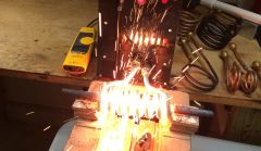 1/2 inch round by 6 incehs - Melting and making a mess
© ReactorForge
-
 1.5 inch square - 650C
© ReactorForge
-
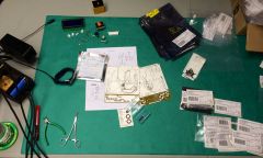 Assembly of the beta induction heater control boards.
© ReactorForge
-
1. Yes, part of the challenge in offering this as a kit is ensuring that the end user does not need to learn 10 new skills from the ground up and also that someone with limited electronics knowledge can assemble such a complex machine safely. Although there will be complex options for the adventurous, basic use of the machine will be no more complex than pushing a button or stepping on a pedal. 2. Yes, set it and forget it. I do not like how the majority of units only show tank current (that big number on the red LED from zero to the low thousands), although it has it's place I will be displaying input current/power as well as allowing the user to set maximums for both input current and working/tank current. (On the chart above I was limiting the tank or working current (violet), there was also a ceiling for the input/mains current (red) that I did not hit in that data capture. 3. After the initial launch I will be open sourcing this project, so yes. However the parts that make these machines expensive can be difficult to source individually. That being said I am working out logistics on a flat rate shipping/import tax rate for the crowdsourcing campaign that will not break the bank. 4. I assume your referring to voltage and such, no. The machine can already operate on 50-60Hz with input voltages ranging from 120/240V single phase and 208/230V three phase (delta). Modification to work on larger power sources is simply a mater of ensuring a few components meet the minimum requirements. To operate on three phase 400/480V for example I would just need to remove the filter capacitor, the other components (currently) can already handle the new peek voltage. Operation at higher voltages (within limit) brings the added benefit of running at lower current which lowers losses thus raising efficiency and reducing wear on the machine a bit. -- As far as the kit goes, I had always planed on having the boards stuffed (small parts all soldered on) so the only connections were screw terminals, plugs and such. This way lack of soldering skills or the proper tools won't ruin your day or your investment, although I may offer multiple versions. Such as a bare bones kit where you would start from the ground up with all the raw materials and pieces as well as the aforementioned ARU kit (almost ready to use) where the smaller blocks are complete you just need to hook them all together and mount them in the case. I am also making the pieces and parts modular which will assist greatly in repair, modification and upgrading. Rather than having the entire system smashed together on one board that costs half the price of the whole unit and is impossible to repair except by an electrical technician, each system and sub system is on it's own board. I've also greatly reduced the size, part count (biggie, fewer failure points) and from an outward visual standpoint the complexity over the low cost Chinese units. Using discreet components does save cost but modules and parts that are made for industrial applications make for a much more reliable machine and are really not unreasonable in price when purchased in quantity. -Josh
-
Hey all this is Josh, Daniel's brother. Looks like Dan has done a good job string you all up and teasing you with red hot glowing pictures! My apologies for not chiming in earlier but the forging side is more my brothers thing and I didn't want to impose on the community. Although after having the chance to tinker around in his shop, I definitely see the draw. There is something almost hypnotic about taking a cold hard piece of metal and breathing life into with heat and hammer. Anyway I just wanted to let everyone know that the third prototype is almost packaged up in it's new case, so Dan will probably have more forge porn for you soon lol. I'm satisfied with it's performance to the point where, after a bit of field testing this version I can finalize kit plans and supply chain to determine a price point. I know this has been going on for a while but it's one thing to build a forge with a fixed coil and a single power setting but quite another to make a machine that can work with a large range of coils and vary the power output at such high power levels (0-25 KVA input power). Most if not all examples of DIY induction heating you can find rarely peek above a couple KW of input power, those levels are fine if your working with small materials and heating small areas but won't cut it as a replacement for a flame forge in most cases. The few high power examples out there fail to address other very serious concerns such as mains power isolation (so you don't die), a usable duty cycle, power control (biggie), and a host of other safety and reliability issues. Power control has been a very important factor in making the next forge do what it needed to do, which is heat larger material without having to make physical adjustments to the inner workings of the machine such as transformer tap adjustments. Basically when heating a large work piece more power is not necessarily required, you just need a lower "gear" when the the part is cold. Similar to a combustion engine, the induction heater's inner workings have a limit or a red line. Once the part does heat up (or the car reaches a higher speed) the gear must be raised to keep it's parts from running wild and throwing a rod, er capacitor. You can achieve this by changing the ratio of a transformer which is how some large industrial units work. However this requires manual intervention or complex moving parts with high power contacts adding to cost and complexity not to mention failure rate. I've gone through multiple iterations of just about ever type of power control and have settled on something that yields quick but smooth control while generating relatively low internal heat. Everything that generates significant heat is water cooled so the case will be sealed up. I've seen the first prototype get totally covered with that black soot/dust junk. I think filters would just be a hassle and get clogged or not used at all. If the inside does need a bit of air cooling I'll just throw in a small radiator and fan attached to the water supply. The electronics have been greatly simplified as well. I've gone from using an analog PLL circuit to control frequency to an all digital setup, with everything being controlled in software I can do so much more and the possibilities for customization are endless. It also takes up much less space, uses less power, is not affected by temperature and sounds cooler. (digital yeeeah, smart phone and stuff...) I know the majority of people interested in building one of these will probably have more interest in the use of the machine rather than how it works, but I hope that some do dive into the theory. It's really quite elegant the way a handful of natural laws come together and make this phenomenon possible. That being said since my brother is showing all the red hot pics I'll show the nerdy ones. This is a screen shot of the live data capture coming from the induction heater, this was key in developing the algorithms and control processes, your mind is able to pieces things together when they are presented in the right format (usually visual for me). I am able to instantly see the results of a given formula or routine and discover other associations that made much of this possible. There is no indicated time base shown but every 7 horizontal squares works out to about 1 second in this case. Walking through the image using the color key for reference, the forge starts out at 10% power (white) while it ramps down from it's maximum frequency (yellow) until it reaches it's resonant frequency. While this is happening the program is reading the phase angle and automatically calculating the set point to determine the resonance frequency. Phase error also come into play here as it must be below a certain level and also affects the rate of change in error correction. Once lock is achieved, the low power hold is released an the inverter current (violet) is allowed to ramp up to the maximum set inverter current (dark yellow). After running a couple seconds you can see that I increased the maximum inverter current twice then decreased it. During this the resonant frequency does not change, the inverter current hugs the set point tightly however the mains current draw (red) does not. You can see this effect more so in the next two events. In the last two events on the chart I am removing the work pice (4" x 1.5" sq bar) from the coil while the unit is running. In the first event I slowly and smoothly remove the work coil, the inverter current remains stable but the input power level (mains current) is lowered. You can also see that the resonant frequency lowered and things get a bit noisy on the phase angle due to the unloaded work coil. In the second event I yanked the work piece out and put it back quickly after the power stabilized. There is a fault routine set up (1 of about 10 so far) to halt the unit if that peak is too high relative to the present power level (one more vertical square and it would have triggered at this level). Back to the mains power dip (red), you can see that when the work pieces is removed from the coil, very little input power is needed to maintain the same output power, this is where the "gear" is raised all the way up to over drive in this case, since we are just coasting downhill with no load. Once the work piece is reinserted into the coil it's all up hill and we need to lower the gear again, very similar to a Continuously Variable Transmission in operation. FAQ 1. When I say "it ramps down from it's maximum frequency (yellow)" but you see the ramp going up, that's because the yellow line is a representation of the time delay creating the frequency, so as time increases frequency decreases. http://www.iforgeiron.com/gallery/image/38100-reactor-forge-data-capture/ Full Size Image Link I also want to say that I'm not reinventing the wheel here, but at times the wheel can be over priced, over rated and behind on technology. Many over seas units toy with the numbers (input vs output power etc) to make it sound like your getting more than you are paying for when in-fact your getting less, like the old RadioShack 1000 Watt amplifier (4 channels x 10 x RMS x BS Marketing). That being said I'm not knocking them all, there are some great units out there at decent prices. And support goes a long way, an ounce of support is worth a lot of $ imo. As Dan stated I do plan on making this an open source community project and offering a kit since many of the parts must be bought in bulk to make pricing feasible. I may also offer an ARU kit (almost ready to use), with things like the control board stuffed and read to go so that the only requirements are mechanical assembly (i.e. limited to no electronics work). I hope you are all enjoying your work and your hobbies, hopefully mine can improve your experience and create new ones in the near future. -Josh
-
 This is a screen shot of the live data capture coming from the induction heater, this was key in developing the algorithms and control processes, your mind is able to pieces things together when they are presented in the right format (usually visual for me). I am able to instantly see the results of a given formula or routine and discover other associations that made much of this possible.
© ReactorForge